Review

Evolution of Tunneling Hydro-Technology: From Ancient Times to Present and Future

by
Andreas N. Angelakis
1,2,*,
Cees W. Passchier
3,
Mohammad Valipour
4,
Jens A. Krasilnikoff
5,
Vasileios A. Tzanakakis
6,*,
Abdelkader T. Ahmed
7,8,
Alper Baba
9,
Rohitashw Kumar
10,
Esra Bilgic
11,
Andrea G. Capodaglio
12 and
Nicholas Dercas
13
1
School of History and Culture, Hubei University, Wuhan 430061, China
2
National Foundation for Agricultural Research, Institute of Iraklion, 71307 Iraklion, Greece
3
Institute Geosciences, University of Mainz, 55128 Mainz, Germany
4
Department of Engineering and Engineering Technology, Metropolitan State University of Denver, Denver, CO 80217, USA
5
Department of History and Classical Studies, School of Culture and Society, Aarhus University, 8000 Aarhus, Denmark
6
Department of Agriculture, School of Agricultural Science, Hellenic Mediterranean University, 71410 Iraklion, Greece
7
Civil Engineering Department, Faculty of Engineering, Islamic University of Madinah, Medina 42351, Saudi Arabia
8
KSA & Civil Engineering Department, Faculty of Engineering, Aswan University, Aswan 81528, Egypt
9
Department of International Water Resources, Izmir Institute of Technology, Izmir 35430, Türkiye
10
College of Agricultural Engineering and Technology, SKUAST—Kashmir, Srinagar 190025, India
11
Department of Civil Engineering, Izmir Institute of Technology, Izmir 35430, Türkiye
12
Department of Civil Engineering & Architecture, University of Pavia, 27100 Pavia, Italy
13
Department of Natural Resources Management and Agricultural Engineering, Agricultural University of Athens, 11855 Athens, Greece
*
Authors to whom correspondence should be addressed.
Hydrology 2023, 10(9), 190; https://doi.org/10.3390/hydrology10090190
Submission received: 9 August 2023 / Revised: 7 September 2023 / Accepted: 8 September 2023 / Published: 20 September 2023
(This article belongs to the Topic Hydrology and Water Resources in Agriculture and Ecology)

Abstract

:
Water tunnels are one of the oldest hydro-technologies for extracting water resources and/or transmitting them through water distribution systems. In the past, human societies have used tunneling for various purposes, including development, as a measure to enable underground resource extraction and the construction of transportation networks in challenging landscapes and topographies. The development of hydro-technology potentially involves the construction of tunnels to feed aqueducts, irrigation and waste water systems. Thus, the ability to make and maintain tunnels became an important component in creating lasting and sustainable water systems, which increased water supply and security, minimized construction costs, and reduced environmental impact. Thus, this review asks how, when and why human societies of the past included tunneling for the development of lasting water supply systems. This review presents a comprehensive overview across time and space, covering the history of tunneling in hydro technology from antiquity to the present, and it ponders how past experiences could impact on future hydro-technological projects involving tunneling. A historical review of tunnel systems enhances our understanding of the potential, performance, challenges, and prospects associated with the use of hydro-techniques. In the past, as the different examples in time and space demonstrate, tunneling was often dedicated to solving local problems of supply and disposal. However, across the world, some features were repeated, including the need for carving through the living rock or digging to create tunnels covered with stone slabs. Also, the world-wide use of extensive and costly tunnel systems indicates the high level of investment which human societies are willing to make for securing control over and with its water resources. This study helps us to gather inspiration from proven technologies of the past and more recent knowledge of water tunnel design and construction. As we face global warming and its derivate problems, including problems of water scarcity and flooding, the ability to create and maintain tunnels remains an important technology for the future.

1. Prolegomena

By studying the past we learn about the present and are planning anything for the future.
Andreas N. Angelakis
Traditional water tunnels were constructed mainly for the exploitation of groundwater in arid and semi-arid regions. These technologies presented major achievements in this scientific field throughout the millennia [1]. It is not easy to study past water tunnels and demonstrate their sustainability. However, Barghouth and Al-Sa’ed [2] presented an overview of the sustainability of ancient water supply systems in Jerusalem from the Chalcolithic period (ca 4500–3200 BC) to the present. Ancient evidence and landscape settings indicated that water resources management in Jerusalem was based on underground hydro-structures. Sustainable water supply facilities were erected, consisting mainly of well-developed water tunnels or other, similar underground hydro-technologies, to supply the town and its agricultural developments, showing that irrigation was practiced for many centuries in that area.
Another example from India demonstrates how traditional water tunnels have been used for centuries to tap into groundwater resources, particularly in arid and semi-arid regions, described in this manuscript in detail. These hydro-technologies have been a significant achievement in the field of water management, and their sustainability can be observed through the ages. The Indus Valley Civilization in ancient India had an extensive network of underground channels, which are called karez there. Details are provided on those underground aqueducts which, in some parts of the world, are named qanats [3]. They are also known as foggaras and khettaras, and were used mainly for irrigation and other purposes [4]. In modern times, India has made significant progress in tunneling engineering. For example, the Mumbai Metro Rail Project has included the construction of a 33.5 km long underground section, which was dug using tunnel boring machines (TBMs) to reduce the cost and duration of tunneling while minimizing environmental impact [5]. Furthermore, the Chenani–Nashri Tunnel, India’s longest tunnel, was built using the New Austrian Tunneling Method (NATM), a sustainable and adaptable approach to tunneling that minimizes resource consumption while enhancing worker safety [6,7]. As India continues to invest in infrastructure, it is anticipated that it will make further strides in tunneling engineering, contributing to sustainable development in the country. In addition, tunnels for drainage purposes were developed in central Greece from the end of the Bronze Age. It should also be noted that sometimes tunnels were surface-cut and covered for crossing a watershed, and “valley-side” tunnels were built to pass steep rock walls or to protect an aqueduct in unstable geology. Also, the shafts-and-galley technique was developed, which is known as qanat [8,9]. These are, moreover, discussed in the main text.
The sustainability of ancient water supply systems in India can be seen in the karez system, which is prevalent in the western regions of the country. The karez system dates back to the 2nd century AD at least; it is an underground water management system that collects water from mountain springs and channels it through a series of tunnels to irrigate agricultural land [10]. Similarly, in the southern state of Tamil Nadu, a network of underground tunnels known as “Eri-pattu” has been used since ancient times to provide irrigation to paddy fields. These tunnels collect rainwater during the monsoon season and store it underground, providing a year-round supply of water for irrigation [11]. In recent times, modern technologies such as bore wells and tube wells have become more prevalent in India, but traditional water tunnels are still used in many parts of the country, especially in rural areas. These hydro-technologies have played a crucial role in sustaining agriculture and ensuring the availability of water for domestic use [12].
This paper deals with the construction of water tunnels throughout history [13,14,15]. It focuses on major water tunnels built as excavation structures in solid rock or sediment, meant to transport flowing water, and it excludes tunnel-like structures built by an excavation of a trench from the surface and the insertion of pipes or masonry-covered channels, such as the main structure of many aqueducts and drains.
This review study is divided into six sections, which include geographical and chronological developments as well as observations on various types of tunneling hydro-technologies and practices. Section 1, the prolegomena, is an introduction to the subject. Section 2 elucidates the distinct histories of tunneling hydro-technologies from the prehistoric to the Medieval Era. Section 3 deals with tunneling hydro-technologies in the Early and Mid-Modern periods, and Section 4 discusses tunneling hydro-technologies in contemporary times. Section 5 deals with emerging trends and possible future challenges of tunneling hydro-technologies and practices. Finally, Section 6, the epilogue, comprises conclusive remarks and highlights.

2. Tunneling: From the Prehistoric to Early Medieval Era (ca 7600 BC–1453 AD)

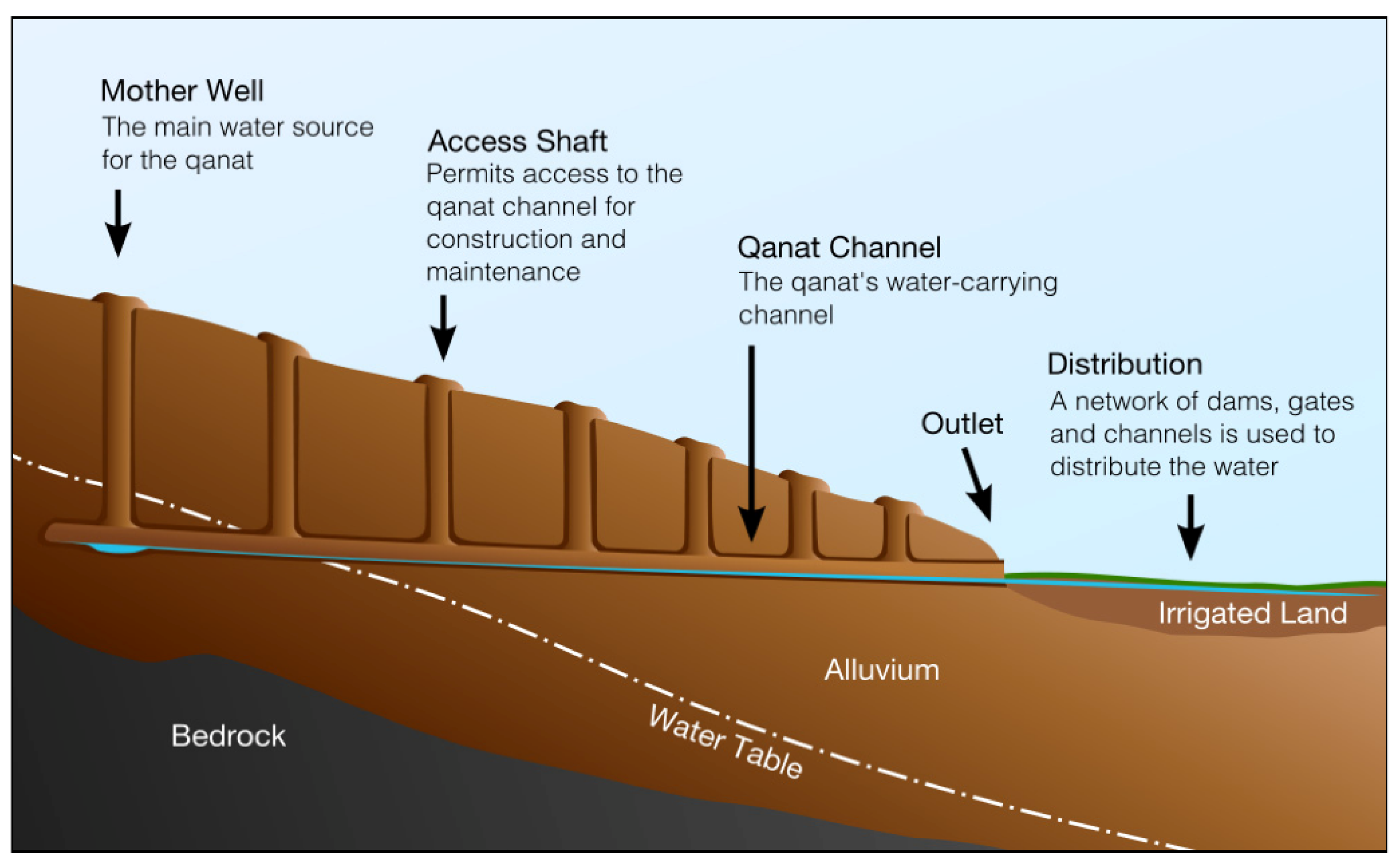
2.1. Persian and Other Prehistoric Civilizations (ca 7600–110 BC)

Located in an arid and semi-arid region of Asia, ancient Persia (today, Iran) was a dry country that had always faced water shortage problems. Ancient dams, irrigation canals, and qanats show the long-lasting struggle of people to deal with drought. To satisfy the increasing demand for water due to the increasing population, Persians invented a new system to bring groundwater to the surface using gravitational force. This tunneling system, which is called qanat, is still in use and some of them date back 3000 years. Today, there are about 32,000 qanats in Iran, which provide about 10 billion m3/yr. Qanat was introduced to other regions of the world (e.g., Japan, Egypt, Oman, Spain, and Chile), and it is thus considered the main contribution of Persians to hydraulic practices. Qanat has a main sloping tunnel and many shaft wells, which together bring water from a high mountain region to low-elevation lands. Compared to deep wells, qanats are cost-efficient and long-lasting in transferring water without requiring energy. They also balance natural inflow and outflow [16,17].
Although thousands of years have passed since then, this method is still used in an important proportion of rural, urban, and agricultural water supply. Using this method, Persians/Iranians have been successful in the development of the sustainable exploitation of groundwater and have withstood the drought conditions in Iran [16,18].
The construction of the qanat was undertaken by skilled laborers and exclusively with hand labor. The process was initiated by the search for an appropriate mother well (probably near mountainous areas). For this purpose, some test wells were dug and checked for the groundwater level. After decisions were made about the mother well location, paths towards irrigated lands were defined on the ground. Then, the work team began digging the main tunnel. To be able to work underground (having enough oxygen, sending out the unnecessary soil, and going out and coming back to the tunnel) vertical shafts were established over the path. A schematic process of a qanat construction is shown in Figure 1.
The elements of a qanat can be defined as follows [16,17]:
Appearance: The place where water comes into view on the surface (tunnel reaches the Earth’s surface).
Tunnel: The canal, with a section resembling a horseshoe inside the ground, featuring a gentle slope for water conveyance from the aquifer to the appearance.
Wet zone: The infiltrating walls inside the gallery of a qanat. The discharge rate is directly dependent upon the wet zone. Indeed, this is part of the tunnel which goes below the groundwater table.
Dry zone: A portion of the gallery between the wet zone and the appearance. The canal was gradually cut deeper due to the decline of the water table.
Shaft: The dry vertical wells situated across the gallery facilitated soil extraction as well as ventilation and dredging. The distance between the two shafts was based on the depth of the qanat and the air passage. The nearer the shafts were to the mother well, the deeper they were.
Mother well: The furthest, water-infiltrating well is called the mother well.
Qanat has many advantages, namely, securing water for irrigation and household consumption in arid regions, balancing the use of groundwater, and low maintenance and operation costs. At the same time, qanats are vulnerable to floods and earthquakes, and they cannot be used for exploiting water from deep layers. Also, in comparison to wells, qanats are more lasting and sustainable and have no energy cost for exploiting water.
Qanat routes need to be regularly cleaned and maintained because they are subjected to damage and destruction by flash floods. To prevent shafts from being filled with sand, they are covered with stone slabs or other objects. One of the famous qanats in Iran is shown in Figure 2 (i.e., Kish qanat).

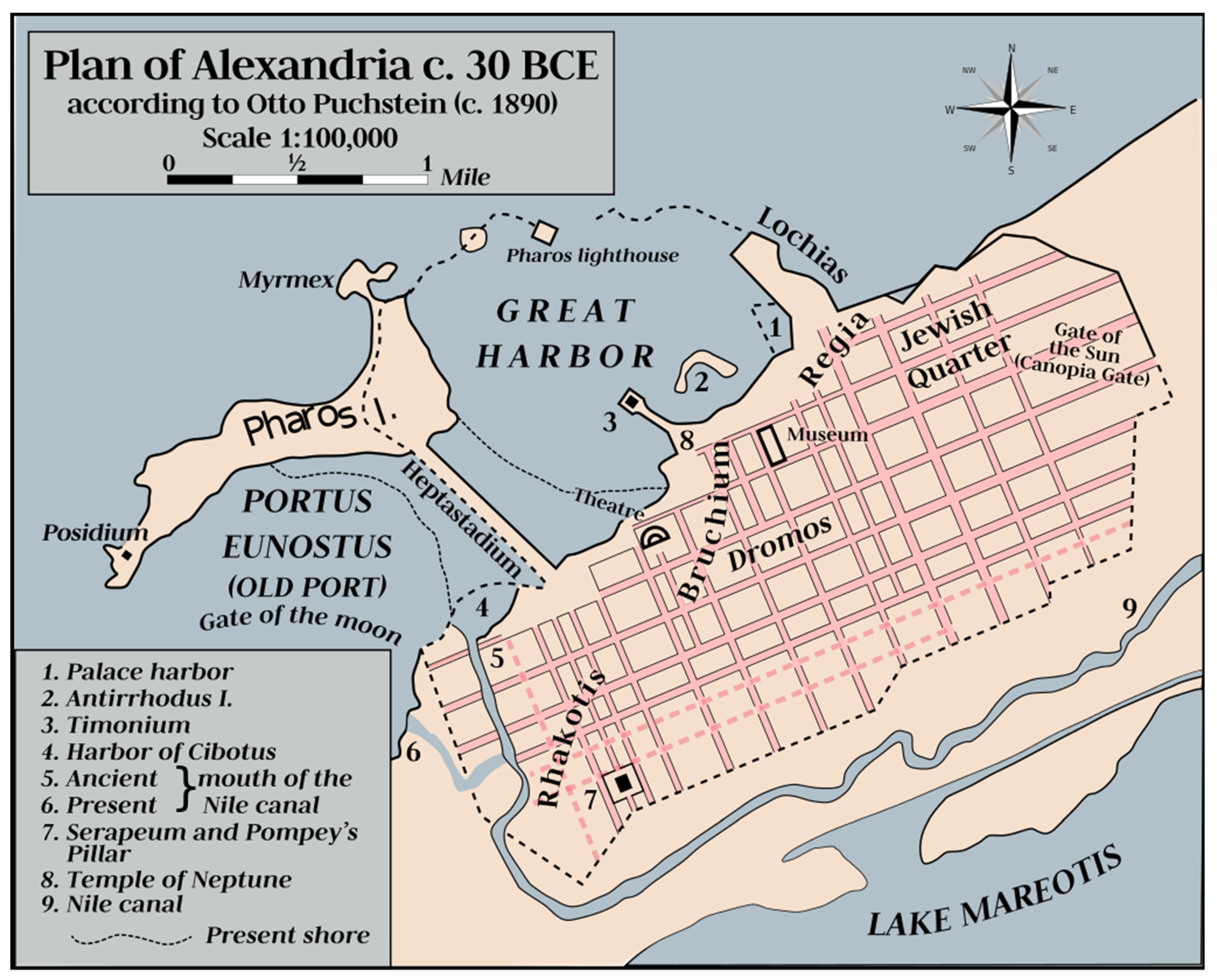
2.2. Early Ancient Egyptians and Other Civilizations (ca 4000–30 BC)

In Egypt, one of the oldest civilizations, the River Nile has been the main source of freshwater, supplying about 97% of its water resources. Even places far away from the Nile conveyed its water through open and closed aqueducts. The type of aqueduct used in early Egypt was a very basic structure. It consisted of an open canal excavated between the Nile River and the location which required the water, made from stones. Open and closed aqueducts were applied commonly in pyramids that were constructed by pharaohs close to the Nile shoreline. The aqueducts transmitted water to the bottom of these pyramids. They linked the base of the pyramid and the Nile bed with a huge open canal controlled by massive doors of stone that allowed water to pass from the Nile. For example, under the Giza pyramids, the openings and passageways for water transferring are equal to the size of a football playing area. In addition, many vertical openings and aqueducts were used to control the Nile flood, as these openings were lower than the Nile level and sunk the water into the aqueducts underneath the pyramids [19].
Egyptians also used underground aqueducts to deliver the Nile water to the temples. For example, in 57 BC, Ptolemy III built the Edfu temple, in which there was a room called the chamber of the Nile where the priests of the temple obtained the holy water of the Nile. This chamber received Nile water through a stone-built tunnel with a length of one kilometer up to the Nile shoreline. The Dendera temple also featured a similar chamber and stone tunnel [20].
The Persians invaded Egypt in 525 BC and introduced the technology of the long underground aqueducts. For example, they constructed what they called a quant, or aqueduct, to deliver water to the Kharga Oasis 200 km west of the Nile. The aqueduct was constructed from a slightly sloping pathway underground, which connected with many vertical shafts [21]. Another good example of the digging of an underground aqueduct can be found at the Bahariya Oasis, where many sites display remains of this aqueduct. Moreover, in the northeastern part of the Sinai peninsula, there is a spring called Ain EI Gudeirat, which supplied spring water from an aqueduct that was built hundreds of years ago and recently watered olive trees at a daily rate of 1500 m3 [22,23].
In Alexandria, a city in the northwest part of Egypt, the Greek engineer Archimedes supervised the construction of an overturned (or inverted) siphon to transfer water for kilometers and hundreds of meters of hydraulic heads. These pipes were mostly made of stone and helped transfer Nile water in aqueducts across valleys to the city [24]. A map of ancient Alexandria with a channel of the Nile Delta is shown in Figure 3.
It should be noticed that an Inverted siphon Is not a siphon but a term applied to pipes that must dip below an obstruction to form a “U” shaped flow path. Large inverted siphons are used to convey water being carried in canals or flumes across valleys, for irrigation or gold mining. These siphons were developed in Classical times; however, the Romans used inverted siphons of lead pipes to cross valleys that were too big for the construction of an aqueduct (e.g., Aspendos aqueduct) [3].

2.3. Ancient India (ca 3300–185 BC)

India has a rich history of tunneling and hydro-technology dating back to the prehistoric era. Some of the earliest examples of tunneling in India can be found in the Indus Valley Civilization, which existed from approximately 3300 BC to 1300 BC. One of the oldest known tunnels is the Khandagiri–Udayagiri cave complex in Odisha, which was hidden by sandstone cliffs during the Maurya period (321–185 BC), and was used for residential spaces and places of worship [25]. During the Mauryan Empire (321–185 BC), tunnels were used to irrigate farmland and supply water to the growing population. These types of caves are a series of rock-cut Jain and Buddhist temples that were built by carving into the hillside, creating a network of tunnels and chambers.
During the Indus Valley Civilization, underground drainage systems were constructed to manage water supply and mitigate floods. The Great Bath in Mohenjo-Daro is a remarkable example of their expertise in hydro-engineering. This rectangular pool, built around 2600 BC, was constructed using waterproof bricks and a complex system of water channels and drains [26]. The Harappan city of Dholavira also has a sophisticated water management system that included a series of underground tunnels and reservoirs [27] (Figure 4). The Indus Valley people were innovative in their approach to tunneling and used it as a means of managing water supply and creating efficient irrigation systems.
Finally, there is limited evidence of tunneling in ancient India. However, the Mauryan Empire (321–185 BC) made significant advancements in tunneling technology. Tunnels were used for irrigation, with some examples being the Pataliputra irrigation tunnels in present-day Bihar, India. Additionally, the construction of Emperor Ashoka’s rock-cut edicts, dating back to the 3rd century BC, required extensive tunneling and carving into solid rock [29].

2.4. Minoan and Mycenaean Civilizations (ca 3200–1050 BC)

Most Minoan aqueducts transported water through open channels, but a few examples of covered surface channels have survived. In Knossos, water was transported by closed terracotta pipes and/or open or covered channels of various dimensions through a gravity aqueduct about 0.7 km long [30] (Figure 5).
An advanced hydraulic tunneling technique was introduced by the Minyans of mainland Greece in about 1300 BC, using tunnels for drainage purposes. One prominent example of this is the Akraifnio drainage tunnel, which drained Lake Kopais and used the land for agriculture (Figure 6). The tunnel has a height of 1.8 m and a width of 1.5 m. Sixteen vertical shafts were excavated along the axis of the tunnel, and through those the tunnel was excavated [8].
Several studies on the ancient Kopais drainage system have been carried out by several researchers [31,32,33,34]. According to Knauss [32], Minyans attempted to gain land from Kopais Lake in two main phases. The first phase used earth dams to protect irrigated polders against floods. After a dam’s failure, a second system was developed. The second attempt was based on a 25 km long canal that guided water from the Kopais basin to the natural sinkholes located in the north-eastern part of the area.
The construction of the drainage of Lake Kopais was stopped at the end of the era of Alexander the Great due to the end of the funding of the project. Alexander’s engineer had begun the construction of a tunnel that would lead the water of the lake to the sea. The construction method used the technique of that period: the excavation of vertical shafts, followed by horizontal excavation and the connection of the vertical shafts at the bottom level [35].

2.5. Babylonian, Assyrian, and Other Asian Civilizations

Ancient Babylonian and Assyrian civilizations had advanced knowledge of tunneling and hydro-technology, building elaborate underground aqueducts, tunnels, and canals to manage water supply and irrigation.
The Sultanate of Oman is an arid region, and ever since its early history the country has depended on groundwater as a freshwater resource. They used surface and underground tunnels to convey water horizontally via gravity from groundwater into valleys for irrigation and drinking purposes. They called these tunnels and aqueducts ‘Aflaj’, and they had a long history dating back several thousands of years in Oman [36]. Aflaj is defined as the plural of the term ‘Falaj’, which refers to a channel supplied by a groundwater source. The term Falaj is Arabic and means ‘to divide or split’ [37]. Establishing Aflaj helped ancient Omanis to provide freshwater for communities for different purposes. Omanis classify Aflaj as Ghaily, Daudi, and Ayni. Ghaily Falaj is seasonal, as it relies on a shallow underground source that stops in dry periods. The Daudi provides permanent water flow via the top surface of the valley being used as a transferring channel. The Ayni Falaj derives its water from natural springs and the water is usually hot because it comes from very deep layers [38].

2.6. Iron Age (ca 1050–750 BC)

During the Iron Age in India (ca 1200–750 BC), tunneling technology was used primarily for mining and transportation purposes. The Khetri Copper Mines in Rajasthan, India, dating back to the 8th century BC, are an excellent example of ancient Indian mining operations that utilized tunnels. These tunnels were excavated to extract copper ore from the mines and transport it to smelting facilities. The technology used during this period was primitive, with hand tools being the primary means of excavation. However, the expertise of ancient Indian miners and tunnelers cannot be underestimated, as evidenced by the vast network of interconnected tunnels that were constructed during this period [39].

2.7. Archaic, Classical, and Hellenistic Periods (ca 750 BC–31 BC)

One of the oldest tunnels in the world was built below Jerusalem in the 8th century BC from the Gihon karst spring to the Siloam pool [40,41]. Known as Hezekiah’s tunnel (Figure 7), this 500 m long structure was built by drilling from the spring and the destination pool in two directions (counter-excavated tunnel), meeting in the middle. The tunnel still carries water.
The technologies of hydraulic tunneling developed by prehistoric civilizations were further developed and improved during historical times. Allegedly, in late Archaic Samos, Greece, the engineer Eupalinus constructed the prestigious and renowned tunnel bearing his name, the Eupalinos or Eupalinian aqueduct (Greek: Ευπαλίνιον όρυγμα, i.e., Efpalinion orygma). The evidence of the historian Herodotus for the construction of the tunnel (Histories, 3. 60) potentially connects the construction of the tunnel with the tyrant Polycrates (ruled 540–522 BC). The aqueduct is 1036 m in length and runs through Mount Kastro, and was built to provide fresh water for the island’s main city. The tunnel is the second known tunnel in history to have been excavated from both ends (Ancient Greek: ἀμφίστομον, i.e., amphistomon, having two openings), and the first with a geometry-based approach in doing so [19]. The tunnel is inscribed on the UNESCO World Heritage List along with the nearby Pythagoreion and Heraion of Samos, and it was designated as an International Historic Civil Engineering Landmark in 2017 [42]. Today, the tunnel is a popular tourist attraction and can be visited through its southern entrance. A view of a section of the tunnel and a frequently used entrance is depicted below in Figure 8.
Engineer Eupalinos made an effort to have the two construction teams meet either horizontally or vertically by the employment of the following techniques:
(a)
In the vertical plane, at the start of work, Eupalinos leveled around the mountain, probably following a contour line to ensure that both tunnels were started at the same altitude. He increased the possibility of the two tunnels meeting each other, by increasing the height of both tunnels at the point near the join. In the north tunnel, he kept the floor horizontal and increased the height of the roof by 2.5 m, while in the south tunnel he kept the roof horizontal and lowered the level of the floor by 0.6 m (Figure 8a). His precautions as to vertical deviation proved unnecessary, since measurements show that there was very little error. At the meeting point, the closing error in altitude for the two tunnels was a few millimeters [43].
(b)
In the horizontal plane, Eupalinos calculated the expected position of the meeting point in the mountain. Since two parallel lines never meet, an error of more than 2 m horizontally meant that the north and south tunnels would never meet. Therefore, Eupalinos changed the direction of both tunnels, as shown in the picture (the north tunnel to the left and the south tunnel to the right) (Figure 9b). This gave a catching width that was wider by 17 m so that a crossing point would be guaranteed, even if the tunnels were previously parallel and far away. They thus meet at nearly a right angle [43].
It should be noticed that the water channel used for water transfer was constructed at the bottom of the rock-cut tunnel shown in Figure 8a. The rock-cut tunnel was a working gallery from which the workers could lay the lower-lying terracotta conduit, which still functioned in the time of Herodotus. Later, presumably due to blockage of the pipes, the pipeline was broken open and the water allowed to overflow into the rock-cut channel.
Previously, scholars have used John Camp’s study [44] of the wells of the Athenian Agora and their alleged origin in droughts in the ca 8th and 4th centuries as the impetus for the development of underground aqueducts in mainland Greece. This is a likely supposition; however, the builders of the first, major aqueducts, the so-called ‘tyrants’ of the later Archaic age in the south and eastern parts of mainland Greece and in the Aegean islands, may have had other ambitions as well. The autocratic rulers of the late archaic period probably acknowledged the importance of well-functioning water supplies, both as a means to support the growing populations of cities and as a way to rally support behind their rule ‘outside the law’.
Chiotis and Marinos [9] pointed out that the aqueducts from the ca 6th through the 4th centuries fell into versions, which were either surface-cut and covered channels as in the Peisistratean and Acharnian aqueducts or shafts-and-galley techniques, as in the aqueducts of Aegina and Megara. Furthermore, Chiotis and Marinos [9] pointed out the important discussion of whether there might be a link between these aqueducts and the Persian qanats developed during the Achaemenid Empire (538–323 BC). Basically, and unlike the qanats, which collect water from a mother well, Greek aqueducts of the shafts-and-galley type collect water, ’mostly all along their course in temperate areas.’ Different types of climate, geology, and topography inspired different strategies of technological development.
The mid-sixth century tyrants, the Peisistratids, who governed Athens after the reform period of Solon in 594 BC, have frequently been associated with improvements in the Athenian water supply. The historian Thucydides (2.15.5) attributed alterations to the fountain ‘Enneacrounos’, or ‘Nine Pipes’ to ‘the tyrants’. Later this famous fountain appeared under the name of the nymph Callirrhoe—‘Fairwater’ ([45], 294, et passim). Otherwise, the literature evidence is silent about the construction works of the Peisistratids, and we have to rely on the archaeological evidence for more information about the water supply and construction of tunnels in this period (see further [46,47,48]).
The city-state of Megara, a western neighbor to Athens, saw an erratic political development in the late archaic age, beginning with the tyrant Theagenes, and an oligarchy followed by democracy in the 5th century. The engineer Eupalinos originated from Megara, and it has been suggested that his water-technological interest may have originated in the city’s solutions to water management. A fountain was fed with water from an aqueduct covered with long intersected roof gallery sections ([49]).
The construction of the ancient aqueduct of the Aegean island Naxos, Greece, late in the 6th century BC, may have happened either during the tyranny of Lygdamis or the succeeding brief interval of democracy on the island. The aqueduct ran over 11 km on hillsides at the upper limit of fertile land and consisted of socket-jointed clay pipes of a diameter of ca 0.30 m buried in a ditch ca 1 m underground [50] (Figure 10). Its inclination varied from 0.01 to 0.04%.
Most of the examples of hydraulic tunneling described above were constructed to facilitate the water supply of urban centers, and there seems to have been a keen interest among tyrants, but also later, in democratic Athens, to engage in these projects. As mentioned above, such interest was probably due to the support expected from the population. Furthermore, tunneling associated with water management is probably also found in association with intensive agricultural strategies applied during the Classical Period (ca. 480–323 BC). Some years ago, Moreno [51] argued that an example existed in the Attic deme (local parish) of Euonymon on the southwestern coast of the peninsula. Here, Moreno argued that intensive farming, combining terracing of farmland with extensive tunneling, providing irrigation for the crops and ensured the basis of a lucrative trade in cash crops for nearby Athens. Other types of agriculture of a more extensive nature undoubtedly existed in other locations in Attica, but the southernmost deme of Atene (contra [52], but see [53]), may have shared features with the up-coast example of Euonymon; however, irrigated water of Athens may have been supplied by open conduits.

2.8. Roman Period (31 BC–476 AD)

In the Mediterranean part of the Roman Empire, tunnels were built for (a) the drainage of basins and lakes; (b) the extraction of water from a nappe (spring tunnels); (c) the transport of water in aqueducts; (d) the servicing of harbors, related to silting problems; and (e) for mining gold.

2.8.1. Drainage Tunnels

Some tunnels built in Roman times constitute attempts to drain lakes and use the land for agriculture [14]. The longest Roman tunnel built for drainage is the Lake Fucino tunnel, with a length of 5650 m [54,55,56,57,58]. It was ordered by the emperor Claudius and was built by 30,000 slaves in 11 years in the qanat mode through 40 vertical access shafts. The older drainage tunnels of Lakes Nemi and Albano [13,59,60,61] were meant to stabilize the level of the lakes rather than drain them. They contained screens to block debris from entering the tunnel. Drainage tunnels from the Roman period are also known in Greece (Lake Kopais), Turkey, and France. In Turkey, the 250 m-long Bezirgan tunnel near Kalkan drained a polje [62]. In France, the Étang de Clausonne tunnel drained a shallow lake [63] (Figure 11). This lake blocked the passage of the Nîmes Roman aqueduct that had to be built below the level of the lake, which therefore had to be drained. The drainage tunnel is adjacent to an aqueduct tunnel (Figure 11).

2.8.2. Spring Tunnels

Tunnels dug into solid rock to access groundwater were built to provide water for many ancient aqueducts. They have been thoroughly studied by speleologists in Italy [64], where more than 140 such spring tunnels from Etruscan, Greek, and Roman construction have been described in the “ancient aqueducts of Italy” project [64]. These are complex structures meant to capture enough water to fill an aqueduct downstream. Some are similar in purpose to qanats, but were built by driving a horizontal shaft into the rock without the help of vertical access shafts. Longer spring tunnels, however, were built as proper qanats, with vertical access shafts from which the tunnel was dug in two directions. Examples are tunnels for the Roman aqueducts of Xanthos (Figure 12), Turkey [65]; Sexi, Spain [66,67,68]; Zadar [69,70] and Novalja, Croatia [71]. There are also several examples in the middle east, especially in Syria [72,73]; in Northern Africa [74]; and, curiously, in western Germany [14,15,75]. A unique case is the tunnel that was excavated to tap the underground water source of Uxellodunum during a siege in the Gallic wars to force the inhabitants to surrender [76].

2.8.3. Aqueduct Tunnels

Aqueduct tunnels can be divided into “transfer tunnels” needed to cross below hills and mountains (Figure 13, Figure 14, Figure 15, Figure 16 and Figure 17), and “valley-side” tunnels built to pass steep rock walls or to protect an aqueduct in unstable geology (Figure 18). Transfer tunnels exist both in the counter-excavated mode, digging from two entrances to a meeting point, or, more commonly, in qanat mode (Figure 13 and Figure 14), starting with vertical shafts dug from the surface downwards to a common level, after which the shafts are connected by horizontal tunnel segments. Counter-excavated tunnels have only one meeting point, while qanat-type tunnels have as many meeting points as there are shafts (Figure 14). Transfer tunnels of both types are among the longest tunnels built in the ancient world. They include the aqueduct tunnel of Bologna (18 km long) [15]; the Vernelles tunnel in the Traconnade tunnel of Aix-en-Provence, which passes below a watershed (>8 km long—[14,77]); the Forino tunnel of the Aqua Augusta near Naples (>6 km long [78,79]); the 4 km long Annio Novus tunnel of Valle Barberini [80,81,82]; and the 5 km long tunnel of Cella in Spain [83]. Some other tunnel examples are from Jerusalem and Side (both over 2 km long: [14]); Paterno (1903 m: [78]); Syracuse (1385 m: [15]); Lyon (Mornant tunnel in the Gier aqueduct of Lyon, France, 825 m long: [84]); and several shorter tunnels near Naples [78,85]. A famous aqueduct tunnel of 428 m long exists in Saldae, Algeria [14,86]. This tunnel was described on the gravestone of Nonius Datus, a Roman engineer who specialized in the building of water tunnels. He was asked to solve a problem with this counter-excavated tunnel since the workers passed each other without meeting [14,15]. This is one of the few reports we have of Roman tunnel building written by one of the engineers responsible.
Another interesting tunnel is the 230 m long Bullica tunnel of the Marcia aqueduct, Rome, which consisted of a service tunnel wide enough for carts, from which a lower-lying aqueduct tunnel could be accessed, connected to the access tunnel by shafts (Figure 17c) in the sidewall [81].
Transfer tunnels as mentioned above either had water running on the bare rock if the rock was impermeable, or, more commonly, were plastered (Figure 15b) or had a regular excavated or masonry gutter or even a vaulted channel built inside them (Figure 16). Tunnel workers used oil lamps set in niches to light the workforce, and for maintenance. Commonly, a pilot tunnel was dug first, which was then extended and widened downwards (Figure 15a). Tunnels usually have a rounded vault, but they may also have a flat roof (Figure 14d and Figure 17c).
Since tunnels were not meant to be seen except by maintenance crews, they were purely functional structures and their architectural design was not significant. Therefore, traces of their construction and maintenance are usually well preserved, making it possible to see how they were built. In many tunnels, there are still traces of meeting points where two galleries, dug from opposite sides, met at an angle, or different altitudes (Figure 14).
Although most tunnels have remained unchanged and even lack a constructed water channel, modifications were sometimes made, either widening or narrowing a tunnel (Figure 15). There are also supporting structures, such as a masonry vault or sections of wall-filling in cavities or broken-out sections of tunnel wall (Figure 17a,b).
Many aqueducts have “valley-side tunnels”, most built along steep vertical cliffs, which had to be passed (Figure 18). The technique to build them usually involved “horizontal shafts” or windows cut into the wall of the cliff, probably by workers suspended from above, and then connecting the shafts as in qanat construction. Tunnels of this type are known from Chelva, Spain; Galermi, Sicily, and Cella, Spain (Figure 18). A variation of this type of tunnel, the Gadara tunnel in Jordan, was built by excavating sloping shafts with staircases into the side of a valley, which were then connected [88,89]. This produced the longest tunnel of the ancient world, with a minimum length of 107 km and 2900 access shafts, supplying the city of Gadara with water from springs in Syria. This tunnel was probably built instead of a normal aqueduct channel at the surface to avoid problems of land sliding in the local soft, crumbling limestone [85,88].

2.8.4. Harbor-Related Tunnels

Harbor-related tunnels, built to either divert rivers away from a harbor or to regulate the flow of water into a harbor, are known from Seleucea, Turkey, and Cosa, Italy. The Çevlik tunnels of Seleucia Pieria, with a total length of 875 m [90,91,92], are part of a flood diversion system including dams and channels to keep flood water away from the harbors of Antiochia, the third largest city in the Roman Empire. In Cosa, a smaller structure, the “Tagliata Etrusca”, was dug to avoid the silting of the harbor (Figure 19).

2.8.5. Tunnels Associated with Mining

A special application of water tunnels is those built to support the mining of metals, especially gold. In Spain, the 120 m long Montefurado tunnel (Figure 20a) was built in the time of Trajan to breach a meander of the river Sil and divert it, so that the riverbed could be explored for gold [93]. At the Las Medulas gold mines (Figure 20b), the largest in the Roman Empire [94], tunnels were dug into gold-bearing gravels not to extract the gold, but to assist in the mining process. These tunnels were dug close to the rock wall of the mine, but had no exit; a dammed supply of water upstream was channeled into the tunnels at high velocity, “fracking” the gold-bearing rocks (Figure 20b–d), while continued flow eroded the rock. This is a unique way of using water tunnels in the Roman world.
During the Roman period in India (31 BC–476 AD), tunneling technology was used mainly for water management and irrigation purposes. A notable example is the Kaveri Delta system, which dates back to the 1st century AD and features a network of tunnels and canals that were used to divert water from the Kaveri River for agricultural irrigation. The technology used during this period was advanced, with sophisticated engineering techniques being employed for tunnel excavation and maintenance. Additionally, the ancient Indian system of step-wells, such as the Rani ki vav in Gujarat, was also constructed during this period and utilized tunneling techniques for water storage and distribution [95].

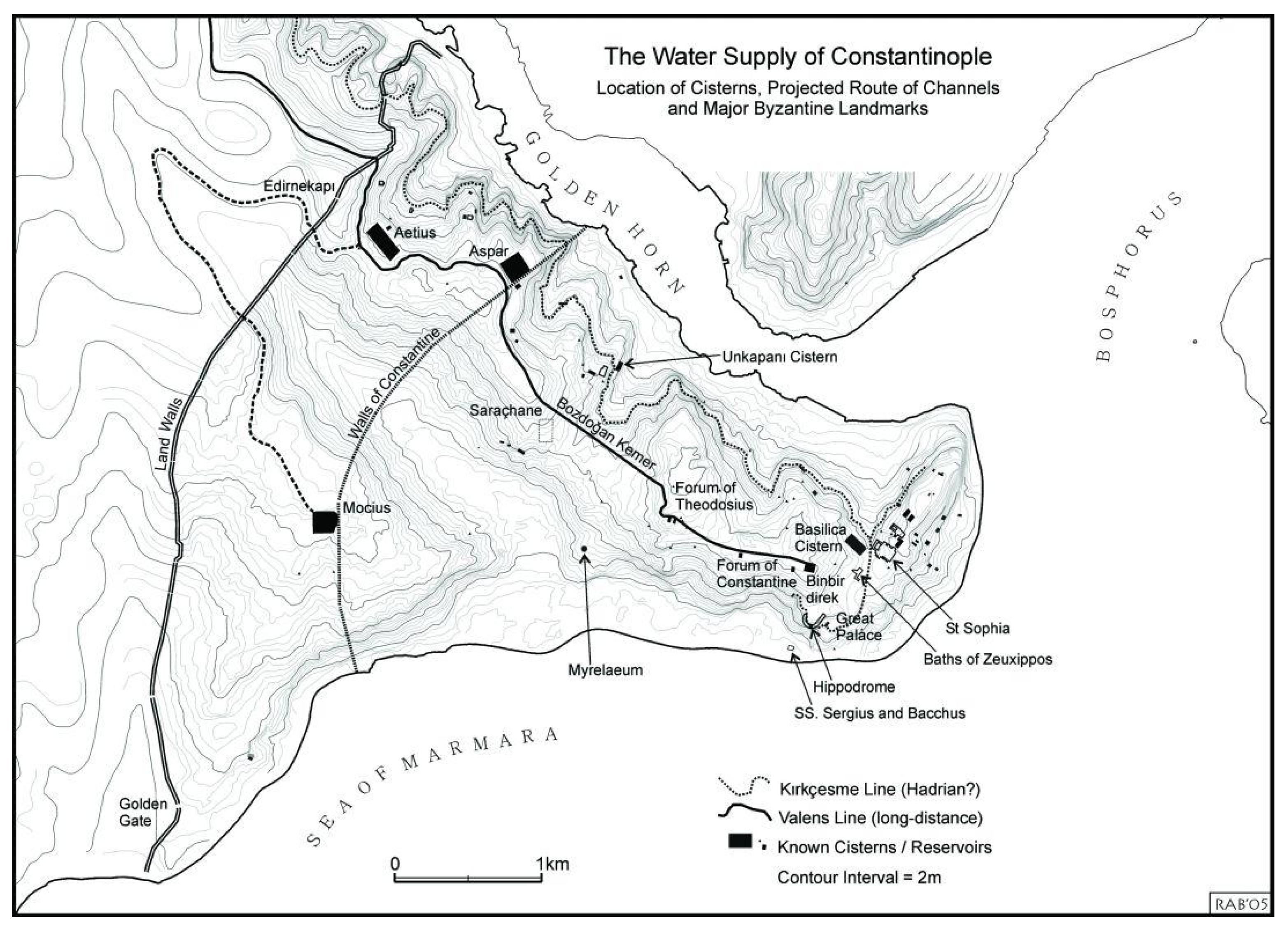
2.9. Byzantine Period (ca 330–1453 AD)

The Byzantine Empire, which replaced the Roman Empire in Anatolia and the eastern Mediterranean, continued the tradition of building advanced water infrastructure, including water tunnels, to supply fresh water to cities and settlements. Istanbul (formerly known as Constantinople) struggled with water problems throughout its history and made enormous efforts to obtain water from nearby locations. After the city was declared the capital of the Roman Empire, Emperor Constantine built the longest line of tunnels in the Roman Empire, which began in Isırancalar (Figure 21) [96]. It is believed that the construction of this line was started by Constantine between 324 and 337 and completed by later emperors [97]. In a study on this subject, the length of this water supply line, determined through field and map work carried out by [98] between 1993 and 1996, was given as 242 km [99], which is 2.5 times longer than the longest Carthaginian water supply tunnel built by the Romans, with a length of 91 km [100]. Later, Valens (364–378) had a water pipeline built to bring water from the Halkalı area [101]. It is also known that Theodosius (379–395) had an aqueduct built to bring water from the Belgrade Forest [102].
Among other water tunnels in this region is the first canal and bridge system, which was completed in 373 AD, and which brought water from the important springs in Danamandra and Pınarca. This system had a total length of 268 km and included an estimated 130 new bridges, varying in size from single-arch to larger-than-average double-arch bridges. All of the enclosed water channels were constructed of mortar-covered stone blocks that were 1 m wide and 1.6 m high, with an arched top. Within the city, the Bozdoğan Bridge (or Valens Aqueduct), with its eighty arches and a length of 971 m, is considered one of the longest water bridges in the Roman world. But that is not all; they built this water channel up to a length of 494 km. With a height of 2 m and a width of 1.6 m, these new tunnels are larger than those built in the first phase [97]. The final water tunnel in Constantine is the Ballıgerme, a wide channel spanning a deep gorge above the Karaman Dere (Figure 22). Both the upper and lower canals then run along the south side of the valley, winding around the elevated ridge crossed by the Anastasian Wall to the southeast [101].
Another tunnel in Anatolia is the Kemer dam, including a water tunnel. It is located near the ancient city of Aspendos in the province of Antalya. The Kemer dam and tunnel is a remarkable Byzantine water project. The tunnel was built to carry water from the Koprüçay River to the city of Aspendos. It was built according to the Roman technique, which typically used stone or rock tunnels. The interiors were often lined with a layer of waterproof mortar or concrete to prevent water leakage and erosion. Another water tunnel is the Perge water tunnel [103]. The ancient city of Perge, also in Anatolia, had a Roman water tunnel system. This tunnel, like others in the region, was used to transport water to the city from distant sources. This tunnel was part of a larger aqueduct system that transported water. The tunnel was often dug by hand, with workers using tools such as picks and chisels. The Perge was constructed with a gradual slope or incline. This slope allowed gravity to move the water through the tunnel without the need for pumps or mechanical devices. There are also tunnels from the Byzantine period and underground aqueducts in Cappadocia, which is known for its unique underground cities. These tunnels were used for protection and as a source of water in times of conflict or siege [104,105,106,107].
There are many long-distance waterways in the Turkish Aegean and Mediterranean regions. These systems include spring water collection chambers, lead, stone, and clay pipes of various sizes, rock-hewn and masonry canals, tunnels over 2 m high, inverted siphons with pressures up to 190 m for lead pipes and 155 m for stone pipes, and aqueducts up to 40 m high. One of the longest Roman water transport routes, at 100 km, leads to Phoceia (Foça). In addition, lengths of 65 km at Pergamon (Bergama), 30 km at Smyrna (İzmir), and 42 km at Ephesus are among the most fascinating examples of various water supply systems in the ancient world. The 3.3 km long stone pipe siphon of the Karapınar water conduit to Smyrna can withstand water pressure of 155 m, while the lead pipe siphon of the Madradağ water conduit to Pergamon can withstand water pressure of up to 190 m. These siphons, dating from the late decades of the first millennium BC Hellenistic period, functioned at some of the highest pressures ever recorded in antiquity. The stone siphon at Aspendos is the longest in Turkey, on arches at 1.7 km. The Soma transport to the demolished aqueduct of Pergamon across the Karkassos (Ilyas) stream would have been 40 m high, making it the second-highest Roman aqueduct after the Pont-du-Gard of Nîmes. Another tunnel system and river detour from the Roman period is the Çevlik Tunnel. Its construction took place between the first and second centuries AD. The 875 m long system had a capacity of 70 m3/s. It included two tunnel segments, 90 and 30 m long. The dimensions were in the range of 6–7 m, and the cross sections were either semicircular or trapezoidal. It was the largest structure at that time. The 250 m long Bezirgan tunnel near Kalkan, which is 1.1 m wide and 2.2 m high, serves as a floodwater conduit for the Karst polje [107].

3. Water Tunnelling in Early and Mid-Modern Times (ca 1453–1850 AD)

During medieval times in India (ca 476–1400 AD), tunneling technology was used for water supply, irrigation, and transportation. Notable examples include the Anicut Dam in Tamil Nadu, the Patal Bhuvaneshwar Cave in Uttarakhand, and the Rani-ki-Vav stepwell in Gujarat. These structures and tunnels demonstrate India’s engineering capabilities and played an important role in the development of hydro-technology infrastructure during this period.
In Egypt’s capital, Cairo, the Citadel Aqueduct was constructed at the beginning of the 13th century by Ayyubid sultans and then completed by the Mamluk State to convert Nile water into a new castle. The aqueduct started from the Nile shoreline, where water was raised by successive waterwheels, and ran into the aqueduct to the Citadel. The aqueduct was raised by a tower of arches constructed from masonry. It was still used during the Ottoman period. Many aqueducts that remain near the Citadel can be seen today, such as the impressive hexagonal tower used for water intake [108,109].
The damage and deterioration of the Constantinople water system that occurred during the Roman period were aggravated by the Latin occupation in 1204, after which the water system became virtually unusable. When Constantinople fell into the hands of the Ottomans in 1453, extensive repairs and additions were made to the system. The Kırkçeşme waterways, originating from the Belgrade forests, are among the most important water sources of Constantinople. In connection with the structures built between 1554 and 1564, 33 arches of different sizes were constructed [110]. The Uzun, the Kovuka, the Moğlova, and the Güzelce aqueducts are the longest ones, with 711 m each. The sixteen different waterways that make up the Halkalı waterways were built between 1453 and 1755. In Constantinople’s past, water and the relative architectural structures were considered very valuable, since the city is shaped by water and filled with life through its dams, arches, fountains, water fountains, spa, and cisterns [101,111]. The Mazul aqueduct, the Kara aqueduct, the Turuncluk aqueduct, and the Bozdogan (Valens) aqueduct, which is now known as one of the arches of the Halkalı Canal and was later restored by the Ottoman Empire, are important Roman aqueducts built in Constantinople in the fourth century [96,101]. The Mâzul aqueduct, commonly referred to as the Mâzul aqueduct, was built around the same time in Constantinople and spans the Uzuncaova stream in the Military District [96]. It was the first aqueduct that transported the water of the Halkalı River. It was built of two stories of limestone blocks and has a height of 19 m and a length of 110 m, containing 13 arches in the upper row and 7 arches in the bottom [96]. After its restoration by Fatih Sultan Mehmed, it was used during the Turkish era and again during the time of Constantine V (741–775) [112]. During the Ottoman era, many dams, aqueducts, rivers, fountains, and basins were rebuilt and new fountains and baths were constructed.
The Halkalı waterways, constructed separately in the 16th century, the Kırkçeşme waterways, built during the Kanuni period, the Taksim Waters, built between 1731 and 1839, and the still-operating Hamidiye and Kayışdağı are the four main categories of water facilities built during the Ottoman period in Constantinople [96,98,99]. With these main water supply lines, there is no place in Constantinople where water does not reach [96]. The cargo of the new waterways built or repaired by Fatih Sultan Mehmet consisted of water from the Istranca Mountains, Belgrade Forest, and real sources. Later, new additions were made to the Marmara Region water facilities, which were named Halkalı waterways due to various sources near Halkalı Village, by many rulers and statesmen [113]. These waterways are Fatih (1453–81), Turunçlu (1453–81), Mahmut Paşa (1453–73), Mustafa III (1757–74), Bayezid (1481–1512), Kocamustafa Paşa (1511–12), Süleymaniye (1557), Mihrimah (1565), Ebussuud (1545–74), Cerrahpaşa (1598–99), Sultanahmet (1603–17), Murat IV (Palace fountains) (1623–40), Köprülü (1656–61), Mahmut I (1730–54), Hekimoğlu Ali Paşa (1732–50), Kasım Ağa, and Nuruosmaniye (1748–55). These waterways were used to supply water to mosques, imamates, fountains, and barracks outside the city. The daily output of these facilities is 4335 m3 [96]. There are four large aqueducts in the Halkalı waterways facilities: Mazul, Kara, Ali Paşa, and Bozdoğan aqueducts [106]. Mazul aqueduct and Bozdoğan aqueduct were built during the Roman era, and later on water aqueducts were constructed over the Halkalı waterways such as Fatih, Turunçluk, and Mahmutpaşa [96,101]. During the reign of Beyazit II, there were 33 water aqueducts, including monumental arches, such as Beyazit waterways, Kırkçeşme waterways, Uzun aqueduct, Kırık aqueduct (Eğri aqueduct, Kovuk aqueduct), Güzelce aqueduct, Moğlova aqueduct, and Paşa aqueduct (Balıkzade aqueduct) [96].
The Kırkçeşme waterways facility collected water from the Alibey and Kağıthane streams, which was then stored in reservoirs and transported to the city through Eğrikapı. Because durable pipes capable of withstanding high pressure were not available at the time, aqueducts were built in valleys and water was transported through them [96]. Uzun aqueduct is the longest arch of all the lines, with a height of 26 m and a length of 711 m. The arches are 4.5–4.6 m wide on the upper row and 3.7–5.2 m wide on the lower row [96]. Kırık aqueduct, also known as Eğri or Kovuk aqueduct, is a three-story arch 35 m high and 342 m long [114]. The Moğlova aqueduct, which is considered an architectural masterpiece of the Kırkçeşme waterway facilities, is a two-story arch that is 35 m high and 258 m long [110]. The geometric structure of the arches is a great engineering achievement. To prevent the arches from tipping over, the base of the legs was widened in the shape of a pyramid so that the arches could be kept unusually thin. To allow the upper part of the lower arch to be used like a bridge, a passage was created through the legs, cleverly connected to the slopes. The legs were given a special shape towards the source to prevent the water from forming a depression in front of them due to the flow [98,99,106]. The Mağlova aqueduct has the largest arch span after the Pont-du-Gard aqueduct in France [114].
The Güzelce aqueduct, across the Cebeciköy Stream, is another aqueduct of the Kırkçeşme waterway infrastructure [96]. Again, Mimar Sinan used a trapezoidal wall system and two-sided buttresses to strengthen the legs. It has 11 openings on the upper floor and 8 openings in the basement, with an opening width of 5.6–6.1 m [114]. It is a two-story building. To resist lateral forces (earthquakes, wind), the legs of this arch were trapezoidal in shape and reinforced with buttresses [98,99,106]. Other important single-story arches include the Kara aqueduct, the Develioğlu aqueduct, the Vâlide aqueduct, and the Alacahamam aqueduct, which was built on a branch of the Cebeciköy stream. The Ali Paşa aqueduct is another arch built under Mimar Sinan. This trapezoidal, two-story aqueduct has a length of 102 m and a height of 16.4 m. The Ali Paşa aqueduct has 13 openings, with a width of 5 m each [96]. During the Ottoman period, aqueducts were built in different parts of the empire. In Constantinople, about forty significant examples are known [110]. The Kırkçeş me water conduit, which is the most important water network in the city, has thirty-five arches, six of which are two- or three-story monumental examples. This water conduit, dating back to the time of Theodosius I (379–395), was destroyed during attacks from the West at the beginning of the 7th century. This facility was almost completely rebuilt by Mimar Sinan between 1554 and 1563 [106,110]. During the reign of Sultan Süleyman the Magnificent, water was brought to the city from sources such as Taşmüsellim, Hıdırağa villages, and the Kurtalçağı stream in the northeast of Edirne in the name of Haseki Hürrem Sultan [115,116].
Although not mentioned in the records, it is accepted that these facilities, including the Hançerli, Ortakçı, Arap, Çifte, Kurt, Yedigöz, Hıdırağa, Üçgöz, Oğlanlı, and Hasanağa aqueducts, were built by Mimar Sinan around 978 (1570–71) during the construction of the Selimiye Mosque and Complex. The Governor of Edirne, İzzet Paşa, repaired these water structures, which were made of cut stone and consisted of pointed arches in a single row, in 1890 after they had been damaged over time [110]. The double-decker aqueduct built in Kavala, Greece, during the reign of Sultan Süleyman the Magnificent is notable among the monumental aqueducts built during the Turkish period in the Balkans. The lower arches were made wider than the upper ones, and lightning holes were drilled between the upper arches. The Mustafa Paşa aqueduct, a 3800 m structure with fifty-five arches in the northwest of Skopje, transports water from Banya Mountain. Bricks were used in the arches, which were constructed with cut stone and sandstone [110]. One of the most important bridges on the Taksim water system, which was built during the reign of Sultan Mahmud I, is the Mahmud I Bridge, which has 21 arches and is 400 m long [96,106,117]. Two rows of arches are only present in the portion that is built along the river.
Another structure with double rows of arches, known as the Ali Paşa Bridge or the Şirin aqueduct, is located on a tributary of the Ayvalı River near the military field. The Avasköy Bridge (also known as Yılanlı aqueduct or Tekaqueduct), was constructed nearby by renowned Ottoman architect Mimar Sinan. Eleven arches make up this bridge, which is constructed of limestone [118]. The Kumrulu Bridge (also known as Akyar Bridge), which has a single arch and is located on the Süleymaniye road, the Kara aqueduct Bridge, with three arches, and the Paşa Bridge, which carries the Turunçlu water to the city at the intersection of the Beyazıt aqueduct, are ordinary water bridges [110]. Also, another aqueduct was constructed by the Grand Vizier Safranbolulu İzzet Mehmed Paşa, and it supplies water to Safranbolu. It is made of mortar and rubble stone, measures 116 m long and 60 m high, and has one major and five tiny arches [110]. The single-pointed arch of the Akdere aqueduct, with a width of 4.10 m and an opening of 1.10 m, traverses the valley as the Kırkgöz water is transported from the Pınarbaşı water source to Kahramanmaraş. The arch, which has a cut stone roof and a base made of rubble stone, is in ruins [110].
India’s history of tunneling and hydro-technology continued to evolve and advance throughout the medieval period, with notable examples including the complex water supply system of the Qutb Minar complex in Delhi, built by the Mamluk dynasty in the mid-13th century AD. During the early and mid-modern times in India (ca 1400–1850 AD), tunneling technology continued to play a vital role in the country’s hydro-technology infrastructure. A notable example is the Rajon Ki Baoli stepwell in Delhi, built during the 16th century AD. This impressive structure includes a series of underground tunnels and chambers that were used for water storage and purification (Delhi Tourism and Transportation Development Corporation). Another significant example is the Brihadeeswarar Temple in Tamil Nadu, built during the 11th century AD, which features a series of underground channels that collect and distribute water for the temple’s use (Archaeological Survey of India).
Furthermore, the Mughal Empire, which ruled over India during the 16th and 17th centuries, contributed considerably to the development of tunneling technology in the country. The Mughals constructed several underground water channels, known as “qanats,” to provide water for their gardens, palaces, and cities. One notable example is the Shalimar Bagh garden in Srinagar, which features a network of underground channels that collect and distribute water from a nearby spring (India Water Portal). Overall, during the early and mid-modern periods in India, continued innovation and developments in tunneling technology were achieved, thus supporting the country’s growing hydro-technology needs.

4. Tunneling in Contemporary Times (1853 AD–Present)

In contemporary times (1853 AD-present), tunneling technology in India has continued to evolve and expand, playing a significant role in the country’s infrastructure development. A major project is the Kaleshwaram Lift Irrigation Project in Telangana, which includes the construction of a network of tunnels to transfer water from the Godavari River to drought-prone regions of the state (India Today). Another notable example is the Chenani–Nashri Tunnel in Jammu and Kashmir, which is the longest road tunnel in India, measuring 9.2 km, and was constructed to provide all-weather connectivity between the two regions (National Highways Authority of India). Additionally, tunneling technology has been used in the construction of metro rail systems in cities such as Delhi, Mumbai, Kolkata, and Bengaluru, to alleviate traffic congestion and provide fast and efficient transportation (The Indian Express Journalism of Encourage, 2017). These projects show that tunneling technology continues to be a critical tool for meeting India’s growing infrastructure needs in contemporary times.
A big project was constructed in the area in the Southeastern Anatolia region of Turkey, which includes the provinces of Adıyaman, Batman, Diyarbakır, Gaziantep, Kilis, Mardin, Siirt, Şanlıurfa, and Şırnak, defined as the “GAP Region” (Southeastern Anatolia Project) [119]. The GAP “Southeastern Anatolia” project is one of the most significant water-based development projects in the world in terms of size and impact, and the largest integrated water resources project in Turkey. Irrigation systems and drainage requirements in the Tigris and Euphrates basins have been studied on a project-by-project basis as part of GAP. Numerous studies have been conducted to examine the water resources, irrigation systems, and water distribution methods based on the data and field observations collected during these studies in terms of current demands, as well as drainage requirements and systems, water control structures, covers, and efficient water use [119]. This region, bordering Syria to the south and Iraq to the southeast, comprises 20% of Turkey’s irrigable 8.5 million hectares of land and consists of large plains in the river basins of the lower Tigris and Euphrates rivers in the GAP region. Within GAP, 22 dams, 19 hydropower plants, and an area of 1,762,000 hectares have been planned for economically viable irrigated agriculture, with a total installed capacity of over 7476 megawatts and an annual electricity production of 27 billion kilowatt hours [119]. One of these structures is the Şanlıurfa irrigation tunnel. The Şanlıurfa tunnels are located in the Southeast Anatolia region of Turkey. They consist of two parallel tunnels with a total length of 26.4 km, running from the Atatürk Dam reservoir to 5 km northeast of Şanlıurfa. The tunnels are among the longest irrigation tunnels in Turkey and worldwide. Construction began in 1981 and the tunnels, which are among the largest structures in the GAP, were planned to irrigate about 476,000 hectares of land, including about 358,000 hectares of land by gravity and 118,000 hectares of land by pumping. The water tunnels consist of two circular concrete-lined tunnels, each 7.62 m in diameter and 26.4 km long. The total length of the tunnels, including the transport and connecting tunnels, is 57.8 km. The water taken from the Atatürk reservoir through the tunnels, amounting to 328 m3/s, is to be transferred to the Harran and Mardin plains. In the system consisting of two parallel tunnels, the distance between the tunnels from axis to axis is 40 m. A connecting tunnel has been opened between the tunnels every 500 m so that the excavated material can be easily transported outside, and the excavation and concreting work can be carried out simultaneously. There are 52 connecting tunnels in total. Good ventilation is very important in such a long tunnel. For this purpose, the chimneys in the middle of the connecting tunnels were opened to supply both tunnels. There is a chimney approximately every 1500 m, the depth of which varies between 65.24 m and 207.95 m. The total number of stacks is 23. The tunnels are laid out according to the direction of water flow [120].
In Athens, the capital city of Greece, a contract was signed between the Greek Government, the Bank of Athens, and the American firm ULEN in 1952, for the financing and construction of the new water supply project. The first major work was the construction of the Marathon Dam (1926–1929). The dam is 54 m high and 285 m long and it is considered unique because it is entirely paneled externally with Pentelikon white marble. The Boyati Tunnel, 13.4 km long, 2.6 m wide, and 2.1 m high, was constructed to transport water from the Marathon impounding reservoir to a new water treatment plant in Athens [8]. In 1956, the water from the Yliki Lake was added to the system, and in 1981, the Mornos dam and aqueduct were inaugurated. The Mornos dam is one of the highest earth dams in Europe, with a height of 126 m. The Mornos aqueduct, which transports water from the Mornos reservoir to Athens, is the second longest aqueduct in Europe. It has a total length of 188 km, made up of 15 tunnels of 71 km in length and 3.2 m in diameter, 12 siphons (7 km), and 15 canals (110 km). The first time that a TBM was used in Greece for the excavation of the Gkiona Tunnel, 14.75 km in length [121]. Finally, the last major work, which provided Athens with additional water in 2001, was the Evinos River diversion to the Mornos impounding reservoir, consisting of the Evinos Dam and a diversion tunnel. Works began on the Evinos in 1992 and were completed in 2001. The major structures of the project are a 120 m high earth-fill dam, with a dam volume of 12 million m3, a total barrage capacity of 120 million m3, and the 29.4 km long Evinos–Mornos tunnel, with a 4.2 m excavation diameter and a 3.50 m internal diameter [8]. The tunnel is one of the longest hydraulic tunnels in the world realized using the TBM method. The adverse geological conditions, the high cover, and the short construction schedule were a great challenge for the successful construction of this tunnel [122]. The tunnel was completed in just two years, which is considered to be a significant achievement given the project scale. The area covered by this major project is shown in Figure 23.
In the contemporary time the hydrological tunneling has increased significantly in both size and number. A few more examples, indicating their size, are the following:
(a)
The Delaware aqueduct in the New York City water supply system. It was constructed between 1939 and 1945 and carries approximately half of New York City’s water supply of 4,900,000 m3/d. At 4.10 m wide and 137 km long, the Delaware Aqueduct is the world’s longest tunnel. It takes water from the Rondout, Cannonsville, Neversink, and Pepacton reservoirs on the west bank of the Hudson River through the Chelsea Pump Station, then into the West Branch, Kensico, and Hillview reservoirs on the east bank, ending at Hillview in Yonkers, New York [124].
(b)
The Metropolitan Area Outer Underground Discharge Channel is an underground water infrastructure project in Kasukabe, Saitama, Japan. It is the world’s largest underground flood water diversion facility, built to mitigate the overflowing of the city’s major waterways and rivers during rain and typhoon seasons [125]. It is located between Showa and Kasukabe in Saitama prefecture, on the outskirts of the city of Tokyo in the Greater Tokyo Area. Construction started in 1992 and was completed by early 2006.
(c)
In China, a secretive 500 km long irrigation project being built to divert snowmelt from the Altay Mountains to desert areas in its restive Xinjiang region has developed a too-much-of-a-good-thing problem. Workers keep tapping into gushing flows of groundwater, which has slowed construction to a crawl. It was based in part on the 2000-year-old karez system designed by Uyghurs in Turpan, and China began constructing the 514 km long project years ago, in what is reportedly the longest underground irrigation canal system in the world [126]. The project comprises three deeply dug tunnels, the longest of which is the 280 km long Kashuang Tunnel—twice as long as the Delaware Aqueduct, the main channel supplying water to New York City.

5. Emerging Trends of Tunneling Aqueducts

Governments and municipal authorities, faced with the problems of providing infrastructure within and between densely populated megacities, have acknowledged the importance of tunnels for the installation of underground transport corridors, sewerage systems, and utilities. Nowadays, many tunnels are constructed with advanced mechanical TBMs that have been progressively replacing the older drill and blast methods. TBMs can excavate a full circular face to the diameter of the machine, typically from 2 to 12 m, at astonishingly rapid rates when rock mass conditions are excellent. Even so, and despite dramatic improvements in TBM technology [127,128] TBMs are still not good at coping with rapidly changing or poor geologic conditions that can delay or stop the machines, thus increasing risks and costs to the tunnel project [129].
Studies of tunnel projects in the United States [130] have demonstrated that predesign investigations along the tunnel route using geological mapping and core drilling from the surface can mitigate these risks and reduce costs. These direct exploration methods may be enhanced with appropriate geophysical techniques (e.g., electrical and seismic imaging) to investigate the interval between boreholes or in difficult or complex areas (e.g., [131,132]). These studies may benefit global underground engineering researchers for hazard prediction and in establishing early warning systems [133]. In general, we are seeking to advance the application of geophysical methods to solve problems facing remediation professionals concerning fractured-rock aquifers. To this end, we (a) provide an overview of geophysical methods applied to the characterization and monitoring of fractured-rock aquifers; (b) review case studies showcasing different geophysical methods; and (c) discuss best practices for method selection and rejection based on synthetic modeling and decision support tools [134].
Emerging trends in tunneling aqueducts in India focus on sustainability, cost-effectiveness, and innovation. An interesting example of such trends is the use of micro-tunneling, a trenchless technology used to construct small-diameter tunnels for water supply and drainage systems (Indian Geotechnical Society). This technique has been utilized in the construction of the Ganga–Krishna–Pennar–Link Project, a massive water supply project aimed at transferring water from the Ganges and Godavari rivers to water-deficit regions in the southern part of the country. Another emerging trend is the use of pre-cast tunnel segments, which can be quickly and efficiently assembled on-site, reducing construction time and costs (NBM&CW). These segments have been used in the construction of the Mumbai Metro Line 3 tunnel, a massive underground rail project that will significantly improve transportation in the city. Overall, these emerging trends in tunneling aqueducts demonstrate how innovative technology and sustainable practices are being used to meet India’s growing infrastructure needs.

6. Epilogue

It is obvious that the irrigation canals used in modern agriculture still follow the basic technical concepts used in ancient times for the construction of aqueducts. In the past, water sources were usually located outside the cities. Therefore, water was transported through open channels, tunnels, pipes made of various materials, and channels carved into rocks and covered with a lid. Water was transported either under pressure or using gravity in tunnels, galleries, and canals. In gravity conveyance, maintaining the head of the water is critical. In an open channel, gallery, or pipe, water flows freely according to gravity. Since there is no pressure or very little pressure as the elevation rises ahead of the waterway, the pipes are thin. For clay pipes, the thickness is 1–2 cm. In different regions, these pipes are called by different names, including “künk”, “pöhrek”, and “terracotta” (in Italian).
The “inverted siphon” method, also referred to in the literature as “reverse siphon”, was historically used to cross valleys as an alternative to aqueducts. In certain cases, the inverted siphon and the aqueduct were built together, reducing the height of the arch to save costs. These pipelines were built using elements such as earth, stone, and lead. Aspendos in Attalya illustrates these practices: water was transported to the city’s reservoir through two towers 65 m high, which were located 924 m apart from each other. Between these towers, there is a water channel, in ruins, 45.00 m high. In Aspendos, both a stone pipe network and an aqueduct were used. The siphon has a depth of about 20 m, and the diameter of the stone pipe is 30 cm.
The United Nations and other organizations encourage the revitalization of traditional water harvesting and supply technologies in arid areas because they consider it important for sustainable water utilization. A qanat as a tunneling system is a gently sloping subterranean conduit, which taps a water-bearing zone at a higher elevation than cultivated lands. It is used to provide a reliable supply of water to human settlements or for irrigation in hot, arid, and semiarid climates and allows the population to live in a desert area. A qanat system has a significant impact on the lives of water users, as it allows those living in a desert environment adjacent to a mountain watershed to create a large oasis in an otherwise stark environment. The advantages of transporting water underground in the qanat system are obvious, given that qanats are subterranean tunnels that tap the groundwater and lead the water entirely by gravity. As they are often dug into the hard subsoil and, when necessary, lined with relatively impermeable clay hoops, there is little seepage, no change in the water table, no water logging, and no evaporation during transit. The rate of water flow in a qanat is controlled by the level of the underground water table and it therefore exploits groundwater as a renewable resource. Thus, qanats are environmentally sustainable water harvesting and conveyance tunneling techniques through which groundwater can be obtained without causing damage to the tapped aquifer in arid regions ([17,135,136,137]).
The importance of the Kopais project, which was perceived by ancient Greeks, was also recognized in modern times; thus, the drainage of Kopais was among the first land reclamation projects carried out, during the second half of the 19th century, by the newly established Greek state. In this case, a tunnel and a network of ditches were created that sent the waters of the lake to an adjacent lake (Lake Yliki). Modern engineers went further, as they identified the peculiarity of the soil in the Kopais plain, which has an impermeable layer at a shallow depth (~2.00 m) and above it a layer of sand that is under the surface organic layer and a layer of marl. The impervious layer and the sand layer make it possible to apply subirrigation with the use of drainage ditches during the summer. Thus, a network of earthen ditches has been created that drain the area in the winter to Yliki Lake, and in the summer water from Yliki is pumped and led to the ditches. Initially, the system was designed wisely: a suitable level was kept in each ditch, and the plants were irrigated with the sub-irrigation system. Later, pumping with individual pumping stations and sprinkler irrigation was preferred, which is energy-consuming [35].
According to Sir Winston Leonard Spencer-Churchill (1874–1965), “the more you look back in the past, the more you see into the future”. Furthermore, an analysis of ancient tunneling techniques and applications can provide many practical solutions invented in the past that can be applied in the modern world. Our ancestors had no access to engines and modern techniques, but they used simple, energy-saving means. Their inventions and practical applications can therefore find a place in a new, environmentally conscious, and energy-conservative world.
In conclusion, tunneling dates back to prehistoric times, with the use of hydro-technology playing a critical role in creating sustainable systems in tunneling. Many ancient civilizations, such as the Ancient Egyptians, Greeks, Romans Persian, and others used tunnelling, from the simplest form of aqueducts, such as ditches cut into the earth, up to complex structures including horizontal and vertical tunnels. These tunnels were at a lower level than the reservoir and relied on a gravity hydraulic system for transferring and distributing water without employing any extra energy, which may cause negative impacts on the environment. From ancient water management systems to modern tunneling engineering, India has made significant strides in enhancing safety, minimizing costs, and reducing environmental impact. As India continues to invest in infrastructure, it is anticipated that it will make further strides in tunneling engineering, contributing to sustainable development in the country.

Author Contributions

A.N.A. had the original idea and wrote the original draft. J.A.K. contributed to the ancient Greek section and reviewed the manuscript. C.W.P. contributed mainly to the Roman section. V.A.T. reviewed and edited the manuscript A.T.A. reviewed and revised the manuscript. A.G.C. reviewed the manuscript. M.V. contributed to the Iranian section and other prehistoric civilizations and Emerging Trends of Tunneling Aqueducts. A.B. and E.B. contributed to the Roman section and Water Tunneling in Early and Mid-Modern Times. R.K. reviewed and revised the manuscript. N.D. reviewed and revised the manuscript. All authors have read and agreed to the published version of the manuscript.

Funding

This research received no external funding.

Data Availability Statement

Not applicable.

Conflicts of Interest

The authors declare no conflict of interest.

References

  1. Voudouris, K.S.; Christodoulakos, Y.; Steiakakis, E.; Angelakis, A.N. Hydrogeological characteristics of Hellenic aqueducts-like Qanats. Water 2013, 5, 1326–1345. [Google Scholar] [CrossRef]
  2. Barghouth, J.M.; Al-Saed, R.M. Sustainability of ancient water supply facilities in Jerusalem. Sustainability 2009, 1, 1106–1119. [Google Scholar] [CrossRef]
  3. De Feo, G.; Angelakis, A.N.; Antoniou, G.P.; El-Gohary, F.; Haut, B.; Passchier, C.W.; Zheng, X.Y. Historical and technical notes on aqueducts from prehistoric to medieval times. Water 2013, 5, 1996–2025. [Google Scholar] [CrossRef]
  4. Dutt, S.; Gupta, A.K.; Singh, M.; Jaglan, S.; Saravanan, P.; Balachandiran, P.; Singh, A. Climate variability and evolution of the Indus civilization. Quat. Int. 2019, 507, 15–23. [Google Scholar] [CrossRef]
  5. Mumbai Metro Rail Corporation Limited. (n.d.). Metro Line 3—Colaba-Bandra-SEEPZ, Mumbai, India. Available online: https://www.railwaygazette.com/infrastructure/mumbai-metro-line-3-breaks-ground/43391.article (accessed on 7 September 2023).
  6. Tris, T. TBM Launches on Vishnugad-Pipalkoti Hydropower Project. Available online: https://tunnellingjournal.com/tbm-launches-vishnugad-pipalkoti-hydropower-project/ (accessed on 7 September 2023).
  7. Express Web Desk. 10 interesting facts about India’s longest Chenani-Nashri tunnel 2 April 2017. In The Indian Express Jornalism of Encourage (2017); The Indian Express: New Delhi, India, 2017; Available online: https://indianexpress.com/article/india/chenani-nashri-tunnel-inauguration-10-facts-about-indias-longest-tunnel-narendra-modi-jammu-srinagar-4596209/ (accessed on 7 September 2023).
  8. Tsatsanifos, C.; Michalis, I. Tunnelling in Greece: Past, Present, Future. In Proceedings of the 2nd Eastern European Tunnelling Conference, Athens, Greece, 28 September–1 October 2014. [Google Scholar]
  9. Chiotis, E.; Marinos, P. Geological aspects on the sustainability of ancient aqueducts of Athens. Bull. Geol. Soc. Greece 2012, 46, 16–38. [Google Scholar] [CrossRef]
  10. Kulkarni, H.; Rao, G. Karez: An Ancient Underground Water Supply System. In Geospatial Technologies in Urban System Development: Emerging Research and Opportunities; Mukherjee, S., Ed.; IGI Global: Hershey, PA, USA, 2017; pp. 143–157. [Google Scholar]
  11. Sudhakar, G.J.; Amirthalingam, M.; Sumabala, P. Tank irrigation in South India: A case study of Kolavoy tank. J. Indian Hist. Cult. 2007. Available online: https://www.researchgate.net/publication/312838455_TANK_IRRIGATION_IN_SOUTH_INDIA_A_CASE_STUDY_OF_KOLAVOY_TANK (accessed on 17 September 2023).
  12. World Bank. India—Enhancing Water Resources and Water Efficiency Management Project; World Bank: Washington, DC, USA, 2018. [Google Scholar]
  13. Castellani, V.; Dragoni, W. Ancient tunnels: From roman outlets back to the early Greek civilization. In Proceedings of the 12th International Congress of Speleology, La-Chaux-de-Fonds, Switzerland, 10–17 August 1997; pp. 265–268. [Google Scholar]
  14. Grewe, K. Licht am Ende des Tunnels, Planung und Trassierung in Antiker Tunnelbau; Ant. Welt, Sonderh: Mainz, Germany, 1998. [Google Scholar]
  15. Grewe, K.; Tutlies, P. Der Drover-Berg-Tunnel-Wanderweg bei Düren. Fundgeschichten—Archäologie Nordrh. Westfal. Mainz 2010, 4, 403–405. [Google Scholar]
  16. Alemohammad, S.H.; Gharari, S. Qanat: An ancient invention for water management in Iran. In Proceedings of the Water History Conference, Delft, The Netherlands, 17–21 July 2010; Available online: https://www.researchgate.net/publication/321914743_Qanat_An_Ancient_Invention_for_Water_Management_in_Iran (accessed on 18 September 2023).
  17. Boustani, F. Sustainable Water Utilization in Arid Region of Iran by Qanats. 2008. Available online: chrome-extension://efaidnbmnnnibpcajpcglclefindmkaj/https://www.researchgate.net/profile/Fardin-Boustani-2/publication/242784793_Sustainable_Water_Utilization_in_Arid_Region_of_Iran_by_Qanats/links/5467085a0cf2397f7829f966/Sustainable-Water-Utilization-in-Arid-Region-of-Iran-by-Qanats.pdf (accessed on 21 February 2023).
  18. Laureano, P. Water catchment tunnels: Qanat, foggara, falaj. An ecosystem vision. In Proceedings of the EN IWA Specialized Conference on Water & Wastewater Technologies in Ancient Civilizations, Istanbul, Turkey, 22–24 March 2012; pp. 22–24. [Google Scholar]
  19. Angelakis, A.N.; Kavoulaki, E.; Dialynas, M.G. Sanitation and stormwater and wastewater technologies in Minoan era. In Evolution of Sanitation and Wastewater Management through the Centuries; Angelakis, A., Rose, J., Eds.; IWA Publishing: London, UK, 2014; Chapter 1; pp. 1–24. [Google Scholar]
  20. TEW. Tour Egypt Website: “Hourse Temple”. 2023. Available online: http://www.touregypt.net/edfut.htm#ixzz3pVpWqfyx (accessed on 7 September 2023).
  21. Driaux, D. Water supply of ancient Egyptian settlements: The role of the state. Overview of a relatively equitable scheme from the Old to New Kingdom (ca. 2543–1077 BC). Water Hist. 2016, 8, 43–58. [Google Scholar] [CrossRef]
  22. Evans, S. The Palace of Minos at Knossos: A Comparative Account of the Successive Stages of the Early Cretan Civilization as Illustrated by the Discoveries; Reprinted by Biblo and Tannen: New York, NY, USA, 1964; Macmillan and Co.: London, UK, 1921; Volume I–IV. [Google Scholar]
  23. El-Gohary, F.; Angelakis, A.N.; Rose, J. Evolution of sanitation and wastewater technologies in Egypt. In Evolution of Sanitation and Wastewater Technologies Through Centuries; IWA Publishing: London, UK, 2014; Chapter 4; pp. 55–68. [Google Scholar]
  24. Jansen, R.B. Dams from the Beginning. Dams Public Saf. 1980, 1, 1e57. [Google Scholar]
  25. Mishra, U. Shrines as ‘monuments’: Issues of classification, custody and conflict in Orissa. In Negotiating Cultural Identity; Routledge: Delhi, India, 2019; pp. 200–229. [Google Scholar]
  26. Singh, P.K.; Dey, P.; Jain, S.K.; Mujumdar, P.P. Hydrology and water resources management in ancient India. Hydrol. Earth Syst. Sci. 2020, 24, 4691–4707. [Google Scholar] [CrossRef]
  27. Kenoyer, J.M. Ancient Cities of the Indus Valley Civilization; Oxford University Press: Oxford, UK, 1998. [Google Scholar]
  28. Iyer, M. The Best Laid Plans, Deccan Herald. 2019. Available online: https://www.deccanherald.com/sunday-herald/best-laid-plans-713650 (accessed on 7 September 2023).
  29. Thapar, R. Aśoka and the Decline of the Mauryas; Oxford University Press: Oxford, UK, 2012; p. 90. ISBN 9780199088683. [Google Scholar]
  30. Voudouris, K.; Tsatsanifos, C.; Yannopoulos, S.; Marinos, V.; Angelakis, A. Evolution of underground aqueducts in the Hellenic world. Water Sci. Technol. Water Supply 2016, 16, 1159–1177. [Google Scholar] [CrossRef]
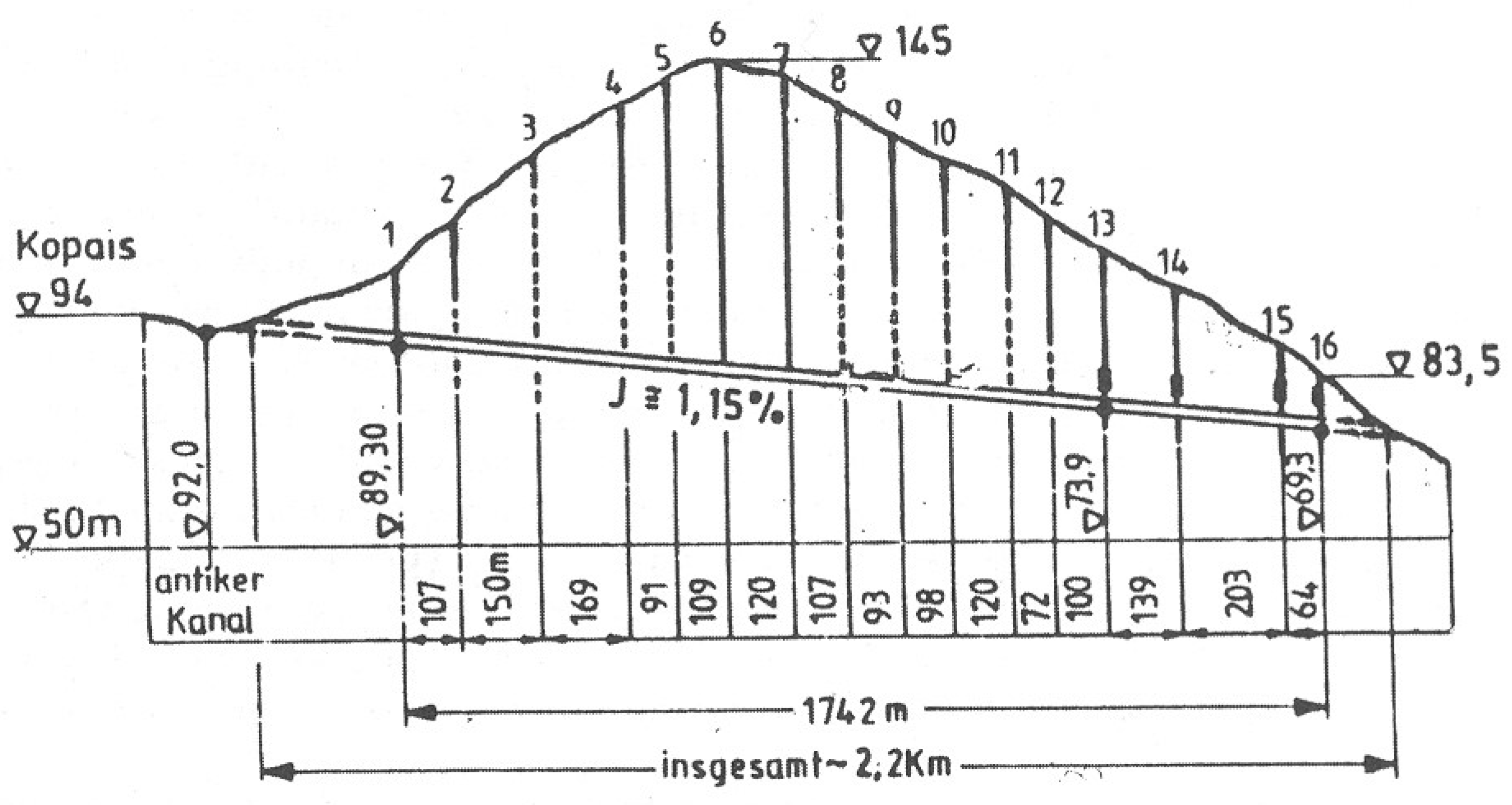
  31. Mamassis, N.; Moustakas, S.; Zarkadoulas, N. The operation of ancient reclamation works at Lake Copais in Greece. Water Hist. 2015, 7, 271–287. [Google Scholar] [CrossRef]
  32. Knauss, J. NE Kopais: Technical–Historical Aspects of the Unfinished Ancient Drainage Tunnel. Proc. Soc. Boeotian Stud. 1995, 2, 83–95. [Google Scholar]
  33. Knauss, J. The prehistoric water management and land reclamation system in the Kopais-Basin, Boiotia, middle Greece. ICID J. 2000, 49, 39–48. [Google Scholar]
  34. Frazer, J.G. Pausanias’s Description of Greece; Macmillan and Co. Limited: New York, NY, USA, 1898. [Google Scholar]
  35. Ghembaza, T.; Windell, D. Mysteries of Lake Copais: The Drainage–Massive Bronze Age and Hellenistic Hydraulic Engineering Works. Open J. Stud. Hist. 2021, 4, 67–84. [Google Scholar] [CrossRef]
  36. Ahmed, A.T. Water quality for irrigation and drinking water use of Aflaj in Oman. Water Sci. Technol. Water Supply 2015, 15, 421–428. [Google Scholar] [CrossRef]
  37. Al-Marshudi, A.S. Traditional Irrigated Agriculture in Oman. Water Int. 2001, 26, 259–264. [Google Scholar] [CrossRef]
  38. Al-Marshudi, A.S. The falaj irrigation system and water allocation markets in Northern Oman. Agric. Water Manag. 2007, 91, 71–77. [Google Scholar] [CrossRef]
  39. Pal, S.; Mukherjee, A.; Senapati, T.; Samanta, P.; Mondal, S.; Ghosh, A. Surface water quality assessment of abandoned opencast coal pit-lakes in Raniganj coalfields area, India. Ecoscan 2013, 4, 175–188. [Google Scholar]
  40. Frumkin, A.; Shimron, A. Tunnel engineering in the Iron Age: Geoarchaeology of the Siloam Tunnel, Jerusalem. J. Archaeol. Sci. 2006, 33, 227–237. [Google Scholar] [CrossRef]
  41. Reich, R.; Shukron, E. The date of the Siloam Tunnel reconsidered. Tel Aviv 2011, 38, 147–157. [Google Scholar] [CrossRef]
  42. UNESCO. Pythagoreion and Heraion of Samos. In UNESCO World Heritage Convention; Retrieved 25 November 2022; United Nations Educational Scientific and Cultural Organization: Paris, France, 2022. [Google Scholar]
  43. Kienast, H.J. The Aqueduct of Eupalinos on Samos; Archaeological Receipts Fund, Directorate of Publications: Athens, Greece, 2005. [Google Scholar]
  44. Camp, J.M., II. Drought and Famine in the 4th Century BC; The American School of Classical Studies at Athens: Athens, Greece, 1982; Available online: http://www.jstor.org/stable/1353941 (accessed on 7 September 2023).
  45. Crouch, D.P. Water Management in Ancient Greek Cities; Oxford University Press: Cary, NC, USA, 1993. [Google Scholar]
  46. Tölle-Kastenbein, R. Antike Wasserkultur; Renate Beck: München, Germany, 1990. [Google Scholar]
  47. Tölle-Kastenbein, R. Das Archaische Wasserleitungsnetz für Athen und Seine Späteren Bauphasen; von Zabern: Reverside, CA, USA, 1994. [Google Scholar]
  48. Wikander, Ö. Handbook of Ancient Water Technology; Brill: Reverside, CA, USA, 2000; Volume 200. [Google Scholar]
  49. Avgerinou, P. The Archaic Underground Aqueduct in Megara. In Underground Aqueducts Handbook; Angelakis, A.N., Chiotis, E., Eslamian, S., Weingartner, H., Eds.; CRC Press: Baton Rouge, LA, USA, 2016; pp. 44–48. [Google Scholar]
  50. Lambrinoudakis, V. Ancient aqueduct in Naxos. In IWA Regional Symposium on Water, Wastewater and Environment-Traditions and Culture; Kalavrouziotis, I.K., Angelakis, A.N., Eds.; Hellenic Open University: Patras, Greece, 2014; pp. 453–459. [Google Scholar]
  51. Moreno, A. Feeding the Democracy: The Athenian Grain Supply in the Fifth and Fourth Centuries BC; Oxford University Press: Oxford, UK, 2007. [Google Scholar]
  52. Lohmann, H. Atene: Forschungen zu Siedlungs-und Wirtschaftsstruktur des Klassischen Attika; Cologne: Böhlau Verlag, Germany, 1993; Volume 1. [Google Scholar]
  53. Krasilnikoff, J. Innovation in ancient Greek agriculture: Some remarks on climate and irrigation in Classical Attica. Class. Mediaev. 2014, 64, 95–116. [Google Scholar]
  54. Ardito, F. L’emissario del Fucino. In Città Sotterranee; Mursia: Milano, Italy, 1990; pp. 44–49. [Google Scholar]
  55. Burri, E. L’emissario Claudio Torlonia. Speleologia 1987, 16, 33–34. [Google Scholar]
  56. Burri, E. Analisi topografica dell’emissario Claudio-Torlonia’. Burri 1994, 234–261. [Google Scholar]
  57. Burri, E. Problemi di conservazione, tutela e fruizione degli antichi emissari artificiali e sotterranei dei laghi endoreici dell’Italia centrale. In Proceedings of the Acts 1st Intentational Conference “Science and Technology for the Safeguard of Cultural Heritage in the Mediterranean Basin”, Catania-Siracusa, Italy, 27 November–2 December 1995; pp. 1595–1601. [Google Scholar]
  58. Döring, M. Der Emissar des Sees von Fucino. Schr. Front. Ges. 1995, 19, 81–110. [Google Scholar]
  59. Castellani, V.; Caloi, V. L’emissario di Nemi (Roma): Aggiornamenti topografici. Opera Ipogea 2000, 1, 11–18. [Google Scholar]
  60. Drusiani, R.; Bersani, P.; Penta, P. The ancient Lake Albano tunnel: Origins and considerations regarding the hydraulic regulation achieved. Water Sci. Technol. Water Supply 2007, 7, 269–276. [Google Scholar] [CrossRef]
  61. Placidi, M. L’emissario del Lago di Nemi. Archeol. Sotteranea 2010, 2, 3–13. [Google Scholar]
  62. Baykan, O.; Alkan, A.; Bacanli, Ü.G.; Baykan, N.; Öziş, Ü. Testing Flood Estimation Methods on Acient Closed Conduits. In Proceedings of the International Balkans Conference on Challenges of Civil Engineering, BCCCE, EPOKA University, Tirana, Albania, 19–21 May 2011. [Google Scholar]
  63. Fabre, G.; Fiches, J.-L.; Marchand, G.; Mathieu, V.; Pey, J. Entre Gardon et Vistre, clausonne, l’étang, ses drainages et l’aqueduc antique de Nîmes. Bull. L’école Atl. Nîmes 2011, 29, 147–204. [Google Scholar]
  64. Parise, M.; Galeazzi, C.; Germani, C.; Bixio, R.; Del Prete, S.; Sammarco, M. The map of ancient underground aqueducts in Italy: Updating of the project, and future perspectives. In Proceedings of the International Congress in Artificial Cavities “Hypogea 2015”, Italy, Rome, 11–17 March 2015; pp. 235–243. [Google Scholar]
  65. Burdy, J.; Lebouteiller, P. L’aqueduc romain de Xanthos. Anatol. Atl. Eski Anadolu 1998, 6, 227–248. [Google Scholar] [CrossRef]
  66. Grewe, K. Die römische Wasserleitung nach Almunecar (Spanien). Der Vermess. 1983, 34, 217–221. [Google Scholar]
  67. Grewe, K. Die römische Wasserleitung von Almuñécar. Antike Welt 1991, 22, 49–53. [Google Scholar]
  68. López, E.S. El acueducto de sexi firmum iulium (almuñécar, granada). Cuad. Prehist. Arqueol. Univ. Granada 2011, 21, 127–158. [Google Scholar]
  69. Ilacovac, B. Wasserbauliche Anlagen des Altertums am Kopaissee. Mitteilungen Leichtweiss-Inst. Wasserbau Tech. Univ. Braunschw. 1981, 71, 275–298. [Google Scholar]
  70. Manenica, H. Urbanizacija Između Raše i Krke u Vrijeme Ranog Principata; Faculty of Philosophy in Zagreb Postgraduate Study of Archeology, University of Zagreb: Zagreb, Croatia, 2015. [Google Scholar]
  71. Marasović, K.; Perojević, S.; Margeta, J. Roman Underground Hydraulic Structures in Dalmatia, Croatia. In Underground Aqueducts Handbook; CRC Press: Boca Raton, FL, USA, 2016; pp. 19–35. [Google Scholar]
  72. Lightfoot, D.R. Syrian qanat Romani: History, ecology, abandonment. J. Arid. Environ. 1996, 33, 321–336. [Google Scholar] [CrossRef]
  73. Lightfoot, D.R. Qanats in the Levant: Hydraulic technology at the periphery of early empires. Technol. Cult. 1997, 38, 432–451. [Google Scholar] [CrossRef]
  74. Wilson, A. Water Management and usage Aksoy T (2015). Aqueducts of Nikomedeia (Izmit). J. Black Sea Res. Inst. 1997, 1, 187–239. Available online: https://dergipark.org.tr/tr/pub/karen/issue/17526/183261 (accessed on 7 September 2023).
  75. Kremer, B. Wasserversorgung aus dem Tunnel: Der römische Qanat von Mehring. Funde Ausgrab. Bez. Trier. 1999, 31, 37–50. [Google Scholar]
  76. Caesar, J. The Gallic War; Edwards, H.J., Ed.; Loeb Classical Library 72; Harvard University Press: Cambridge, MA, USA, 1917; Chapters 41–43. [Google Scholar]
  77. Leveau, P. Les aqueducs d’Aquae Sextiae et la gestion de l’eau sur le territoire de la cité. Cart. Archéologique Gaule 2006, 13, 93–109. [Google Scholar]
  78. Keenan-Jones, D. The Aqua Augusta and control of water resources in the Bay of Naples. In Proceedings of the Australasian Society for Classical Studies Conference, Perth, Australia, 21–22 May 2009; pp. 1–18. [Google Scholar]
  79. Feo, G.D.; Lorenz, W.F. Route and tunnels of the Aqua Augusta for the water supply of Pompeii. Int. J. Glob. Environ. Issues 2015, 14, 177–186. [Google Scholar] [CrossRef]
  80. Van Deman, E.B. The Building of the Roman Aqueducts; Martino Publications: Bologna, Italy, 1934. [Google Scholar]
  81. Ashby, T.; Richmond, I.A. The Aqueducts of Ancient Rome; Oxford University Press: London, UK, 1935. [Google Scholar]
  82. Aicher, P.J. Guide to the Aqueducts of Ancient Rome; Bolchazy-Carducci Publishers: Wauconda, IL, USA, 1995; 183p. [Google Scholar]
  83. Moreno, G.I. Análisis técnico y constructivo del acueducto romano de Albarracín a Cella. In Las Técnicas en la Ingeniería Romana—V Congreso de las Obras Publicas Romanas; Traianvs Publisher: Madrid, Spain, 2010; pp. 225–248. [Google Scholar]
  84. Burdy, J. L’aqueduc romain du Gier. In Préinventaire des Monuments et Richesses Artistiques IV: Gier; Conseil Général du Rhône: Lyon, France, 1996; 407p. [Google Scholar] [CrossRef]
  85. Döring, M. Wasser für Gadara: 94 km langer antiker Tunnel im Norden Jordaniens entdeckt. Querschnitt 2007, 21, 26–37. [Google Scholar]
  86. Cioli, D. Il tunnel dell’acquedotto romano di Saldae in Algeria. Archeol. Sotteranea 2016, 13, 3–23. [Google Scholar]
  87. Garcia Merino, C. Avance al estudio del acueducto de Uxama. In Nuevos Elementos de Ingeniería Romana; Gallo, I., Ed.; III Congreso de las Obras Públicas Romanas: Madrid, Spain, 2006; pp. 167–194. [Google Scholar]
  88. Kempe, S.; Al-Malabeh, A. A 100-km-Long subterraneous Roman Aqueduct in northern Jordan? In Proceedings of the 17th International Congess of Speleology, Sydney, NSW, Australia, 22–28 July 2017; Volume 2. [Google Scholar]
  89. Döring, M. Qanat Fir’aun: An Underground Roman Water System in Syria and Jordan. In Underground Aqueducts Handbook; Angelakis, A.N., Chiotis, E., Eslamian, S., Weingartner, H., Eds.; 6000 BrokenSound Parkway NW, Suoite 300; CRC, Taylor & Francis Group: Boca Raton, FL, USA, 2017; pp. 173–196. [Google Scholar]
  90. Alkan, A.; Özis, Ü. Çevlik historical water tunnel conversion system. In Proceedings of the Historical Water Structures Conference, Proceedings Book, Güneş Ofset, Instabul, Turkey, 26–27 June 2008. [Google Scholar]
  91. Alkan, A.; Özis, Ü. Çevlik historical water tunnel conversion system. In Proceedings of the Historical Water Structures Conference (Regional Meeting for the 5th World Water Forum Preparation); Proceedings Book; Union of Chambers of Turkish Engineers and Architects, Chamber of Civil Engineers İzmir Branch, Istanbul, Turkey, 1–3 October 2015; pp. 93–96. [Google Scholar]
  92. Döring, M. Die antiken Wasserbauten von Antiochia, Türkei. Wasserwirtsch. J. 2012, 102, 10–16. [Google Scholar] [CrossRef]
  93. Lewis, P.R.; Jones, G.D. Roman gold-mining in north-west Spain. J. Rom. Stud. 1970, 60, 169–185. [Google Scholar] [CrossRef]
  94. Matías, R. Las Médulas (León-España): El agua en la ingeniería de la mayor explotación minera del mundo antiguo. Lancia 2008, 7, 17–112. [Google Scholar]
  95. Gupta, A. Stepwells: An architectural legacy of India. In Prakash Books India; 113 A Ansari Road, Daryaganj: New Delhi, India, 2007. [Google Scholar]
  96. Arıkan, B. Istanbul’s historical water channels and the transmission of water through aqueducts. In Proceedings of the 5th Symposium on Strengthening Historical Artifacts and Handing Them down to the Future, Union of Chambers of Turkish Engineers and Architects, Chamber of Civil Engineers İzmir Branch, Erzurum, Turkey, 1–3 October 2015. [Google Scholar]
  97. Crow, J. The Water Supply System of Byzantine Constantinople. A History of Istanbul. 2023. Available online: https://istanbultarihi.ist/554-the-water-supply-of-byzantine-constantinople (accessed on 21 August 2023).
  98. Çeçen, K. The Longest Roman Water Supply Line; The Industrial Development Bank: Istanbul, Turkey, 1996; 230p. [Google Scholar]
  99. Çeçen, K.; Kolay, C. Ottoman Era Waterways of Istanbul; The Industrial Development Bank: Istanbul, Turkey, 2000; 336p. [Google Scholar]
  100. Avcı, I. A Prominent Element in the Historical Development Process of Istanbul: Water; Turkish Engineering News: Instabul, Turkey, 2001. [Google Scholar]
  101. Crow, J.; Bardill, J.; Bayliss, R. The Water Supply of Byzantine Constantinople; Society for the Promotion of Roman Studies Publisher: Instabul, Turkey, 2008. [Google Scholar]
  102. ISKI. Management of Water in Istanbul from Past to Present; ISKI (Istanbul Water and Sewerage Administration) Publications: Istanbul, Turkey, 2009. [Google Scholar]
  103. Yalgin, E. Perge Ancient City. 2023. Available online: https://www.rotasenin.com/perge-ancient-city/ (accessed on 13 August 2023).
  104. Korkanç, M. Tyana aqueducts and stones. Mavi Gezegen Pop. Earth Sci. J. 2019, 26, 49–53. [Google Scholar]
  105. Kahya, E. Cultural tourism in and around the city of Niğde. In Proceedings of the 13th International Congress on Contemporary Research in Social Sciences, Istanbul, Turkey, 6–8 November 2020; pp. 1568–1592. [Google Scholar]
  106. Çeçen, K. Kırkçeşme Waters. TDV Islamic Encyclopedia. 2022. Available online: https://islamansiklopedisi.org.tr/kirkcesme-sulari (accessed on 7 September 2023).
  107. Öziş, Ü. Water Works Through Four Millenia in Turkey. Environ. Process. 2015, 2, 559–573. [Google Scholar] [CrossRef]
  108. Creswell, K.A.C. Muslim Architecture of Egypt; Hacker Art Books: New York, NY, USA, 1978. [Google Scholar]
  109. Williams, C. Islamic Monuments in Cairo: The Practical Guide; American University in Cairo Press: Cairo, Egypt, 2008. [Google Scholar]
  110. Karakaya, E. Aqueducts. TDV Islamic Encyclopedia. 2009. Available online: https://islamansiklopedisi.org.tr/su-kemeri (accessed on 1 May 2009).
  111. Arıkan, B.; Fuat, A.B. Historical aqueducts of Istanbul and dynamic analysis of the Pasha Kemeri aqueduct. In Proceedings of the International Conference on Earthquake Engineering, Skopje, Republic of Macedonia, 29 May 2013. [Google Scholar]
  112. Zehir, C. The historical development of the ottoman water civilization. In Proceedings of the Ottoman Civilization International Symposium, Istanbul, Turkey, 5–8 May 2000; pp. 173–181. [Google Scholar]
  113. Eroğlu, V. Springs that have supplied water to Istanbul throughout history. In Proceedings of the International Symposium on Ottoman Civilization, Istanbul, Turkey, 5–8 May 2000. [Google Scholar]
  114. Öziş, Ü.; Arısoy, Y.; Alkan, A.; Özdemir, Y. General situation of historical aqueducts in Turkey, Civil Engineers Ankara Branch. In Proceedings of the Consolidation of Historical Artifacts and Their Safe Transfer to the Future Symposium-1, Kardelen Ofset Ltd. Şti, Ankara, Turkey, 27–29 September 2007; pp. 555–565. [Google Scholar]
  115. Özer, M.; Dündar, M. Edirne Sarayı Su Yapıları. Belleten 2021, 85, 615–644. [Google Scholar] [CrossRef]
  116. Zeybekoğlu, D.; Çakır, H.K.; Özenç, A. Analysis of water scales in Edirne. Trak. Univ. J. Sci. 2007, 8, 29–33. [Google Scholar]
  117. Şahin, S. Istanbul water structures. In Proceedings of the 4th International Sinan Symposium: Water and Architecturel, Edirne, Turkey, 1–11 April 2008. [Google Scholar]
  118. Cangül, C. Avasköy Aqueduct. Culture Inventory. 2021. Available online: https://kulturenvanteri.com/yer/?P=6952 (accessed on 1 May 2021).
  119. Yenigün, K.; Aydoğdu, M.H. General Evaluation of Irrigation and Drainage Systems Within the Scope of GAP. Turkey’s Larg. Integr. Water Resour. Proj. Water Resour. 2008, 1, 12–32. [Google Scholar]
  120. Yeşilnacar, M.İ. Injection Works in Şanlıurfa Tunnels; General Directorate of State Hydraulic Works (DSİ) Technical Bulletin: Ankara, Turkey, 2005; Volume 100, pp. 1–8. Available online: https://cdniys.tarimorman.gov.tr/api/File/GetGaleriFile/425/DosyaGaleri/600/tb100.pdf (accessed on 8 May 2005).
  121. Wessels, J.I.; Vardakos, S.; Weingartner, H.; Eslamian, S.; Angelakis, A.N. Underground aqueducts: Past, present, and future trends. In Underground Aqueducts Handbook; CRC Press: Boca Raton, FL, USA, 2016; pp. 491–509. [Google Scholar]
  122. Grandori, R.; Jaeger, M.; Antonini, F.; Vigl, L. Evinos-Mornos Tunnel-Greece. Construction of a 30 km long hydraulic tunnel in less than three years under the most adverse geological conditions. In Proceedings of the Rapid Excavation and Tunneling ConferenceRECT, San Francisco, Society for Mining, Metallurgy, and Exploration, San Francisco, CA, USA, 18–21 June 1995; pp. 747–767. [Google Scholar]
  123. Xenos, D.; Passios, I.; Georgiades, S.; Parlis, E.; Koutsoyiannis, D. Water demand management and the Athens water supply. In Water Quality Technologies and Management in Bulgaria, Proceedings of the 7th BNAWQ Scientific and Practical Conference, Sofia, Bulgaria, 20–22 February 2002; Bulgarian National Association on Water Quality: Sofia, Bulgaria, 2002; pp. 44–50. [Google Scholar] [CrossRef]
  124. Department of Environmental Protection—NYC. Announces Major Milestone for Delaware Aqueduct Repair as Tunneling Machine Completes Excavation. New York City Department of Environmental Protection. 2019. Available online: https://www.nyc.gov/site/dep/news/19-062/dep-major-milestone-delaware-aqueduct-repair-tunneling-machine-completes#/0 (accessed on 7 September 2023).
  125. Sheer, J. Metropolitan Area Outer Underground Discharge Channel. AFAR. 2022. Available online: https://web.archive.org/web/20210422165524/https://www.afar.com/places/metropolitan-area-outer-underground-discharge-channel-kasukabe?contex (accessed on 7 September 2023).
  126. Kashgary, J. Chinese Irrigation Tunnel Project in Xinjiang Hits Snag: Too Much Water. Radio Free Asia. 2022. Available online: https://www.rfa.org/english/news/uyghur/tunnel-project-02042022142725.html (accessed on 7 September 2023).
  127. Robert, J. Gravity Mapping and Seismic Imaging of Paleochannels on Large Tunnel Routes in Sydney, Australia. In Near-Surface Geophysics Book; Society of Exploration Geophysicists: Houston, TX, USA, 2005; pp. 503–512. [Google Scholar] [CrossRef]
  128. Biggart, A. A Quiet Revolution. In Tunnels and Tunnelling International; Patrick Reynolds; British Tunneling Society: London, UK, 1999; Volume 31, pp. 18–22. [Google Scholar]
  129. Mitani, S. The state of art of TBM excavation and probing ahead technique. In Engineering Geology: A Global View from the Pacific Rim, Proceedings of the 8th International Congress of the IAEG, Vancouver, BC, Canada, 21–25 September 1998; CRC Press: Boca Raton, FL, USA, 1998; pp. 3501–3512. [Google Scholar]
  130. USNCTT—US National Committee on Tunnel Technology. Geotechnical Site Investigations for Underground Projects; National Academy Press: Washington, DC, USA, 1984. [Google Scholar]
  131. Ishikawa, K.; Feng, S.; Sugiyama, T. Identifying fractured zones using high density electrical prospecting. In Proceedings of the 1st International Workshop on the Application of Geophysics to Rock Engineering, New York, NY, USA, 29 June 1997; Columbia University: New York, NY, USA, 1997; pp. 50–57. [Google Scholar]
  132. Parker, C.; Whiteley, B.; Gee, B. Innovative investigation techniques used for geotechnical modelling of the Northside storage tunnel project, Sydney. In Proceedings of the 10th Australian Tunnelling Conference, Melbourne, VIC, Australia, 21–24 March 1999; pp. 193–205. [Google Scholar]
  133. Khan, M.; He, X.; Farid, A.; Song, D.; Li, Z.; Tian, X.; Ni, M. A novel geophysical method for fractures mapping and risk zones identification in a coalmine, Northeast, China. Energy Rep. 2021, 7, 3785–3804. [Google Scholar] [CrossRef]
  134. Day-Lewis, F.D.; Slater, L.D.; Robinson, J.; Johnson, C.D.; Terry, N.; Werkema, D. An overview of geophysical technologies appropriate for characterization and monitoring at fractured-rock sites. J. Environ. Manag. 2017, 204, 709–720. [Google Scholar] [CrossRef]
  135. Golpasand, M.-R.B.; Do, N.A.; Dias, D. Impact of pre-existent Qanats on ground settlements due to mechanized tunneling. Transp. Geotech. 2019, 21, 100262. [Google Scholar] [CrossRef]
  136. Manuel, M.; Lightfoot, D.; Fattahi, M. The sustainability of ancient water control techniques in Iran: An overview. Water Hist. 2018, 10, 13–30. [Google Scholar] [CrossRef]
  137. Abouei, R. Conservation of Badgirs and Qanats in Yazd, Central Iran. In Proceedings of the 23rd Conference en Passive and Low Energy Architecture, Geneva, Switzerland, 6–8 September 2006; pp. 6–8. [Google Scholar]
Figure 1. Schematic vertical cross-section of qanat construction (adapted from [3]).
Hydrology 10 00190 g001
Figure 2. Τhe Kish qanat: (a) the appearance and (b) view of the main tunnel.
Hydrology 10 00190 g002
Figure 3. Map of Ancient Alexandria.
Hydrology 10 00190 g003
Figure 4. Underground tunnels and reservoirs in the Harappan city of Dholavira: (a) the southern and (b) the eastern views [28].
Hydrology 10 00190 g004
Figure 5. Part of the Knossos palace aqueduct [22].
Hydrology 10 00190 g005
Figure 6. Longitudinal section of the Kopais Minyans tunnel (“Commas” represent here the “dots”).
Hydrology 10 00190 g006
Figure 7. Hezekiah’s tunnel. This tunnel still carries water (Photo Cees Passchier).
Hydrology 10 00190 g007
Figure 8. Eupalinion orygma: (a) a view of the orygma and water channel, and (b) a frequently used entrance.
Hydrology 10 00190 g008
Figure 9. Eupalinos increased the possibility of the two tunnels (right and left sites) meeting each other: (a) in the horizontal plane and (b) in the vertical plane.
Hydrology 10 00190 g009
Figure 10. Naxos tunnel [50].
Hydrology 10 00190 g010
Figure 11. Drainage tunnel of the Étang de Clausonne, France: (a) upstream entrance of the drainage tunnel, originally protected by a metal grille; (b) downstream aspect of the drainage tunnel (left) built to make the Nîmes Roman aqueduct channel (right) pass below the Étang de Clausonne. Only the aqueduct tunnel has carbonate deposits. Water was flowing in opposite directions in the two tunnels. Sernhac, France (Photos Cees Passchier).
Hydrology 10 00190 g011
Figure 12. Spring tunnel of the Xanthos aqueduct, Turkey. The tunnel was partially dug into the rock and extended with ashlars and cover stones. The channel is deepened, leaving a footpath along the side for access: (a) inside, looking to the exterior; (b) inside, looking towards the spring; (c) exterior. The structure is still in use to provide water for irrigation. (d) Branching tunnel of Novalja, Croatia. The tunnel was bifurcated to access two springs (Photos Cees Passchier).
Hydrology 10 00190 g012
Figure 13. Qanat-mode tunnels and shafts: (a) tunnel and (b) vertical access and building shaft with niches for working crews, Tiermes, Spain (Photos Cees Passchier).
Hydrology 10 00190 g013
Figure 14. The meeting point between two excavation sections in several tunnels: (a) the Chelva tunnel, Spain, with horizontal offset. The view is towards the end of a section of the gallery that meets another one at the right-hand side (person visible). (b) A similar meeting point, with a major horizontal offset and small vertical offset, Chelva aqueduct. (c) The meeting point of the aqueduct tunnel of Tiermes, Spain, with a vertical offset. (d) Meeting point with vertical offset in the Sernhac tunnel of the Nîmes aqueduct. The tunnel has a flat roof because of the strong horizontal stratification (Photos Cees Passchier).
Hydrology 10 00190 g014
Figure 15. Water tunnels: (a) tunnel with a pear-shaped profile at Uxama, Spain. This tunnel was probably first dug as a narrow structure, represented by the top, but later widened in its lower part to lower the water level and make access for cleaning crews easier [87]. (b) Tunnel of the Cahors aqueduct, Spain, where a tunnel was made narrower and trapezoidal by inserting wedge-shaped masses of mortar (Photos Cees Passchier).
Hydrology 10 00190 g015
Figure 16. Conduits built into an aqueduct tunnel: (a) Sernhac tunnel, France; a masonry channel was built into the tunnel for passage of the Nîmes aqueduct (Photo (a)—Cees Passchier). (b) Cave de Curée, with a vaulted aqueduct channel in the tunnel, part of the Gier aqueduct of Lyon, France—(http://www.romanaqueducts.info/, accessed on 15 August 2023).
Hydrology 10 00190 g016
Figure 17. Constructions improving the shape of aqueduct tunnels: (a) masonry wall section in a tunnel where the sidewall was broken out. Traconnade aqueduct of Aix-en-Provence (France). (b) A vault structure over a tunnel that was dug from the top and then closed with a vault. Traconnade aqueduct, quarry of Santa Anna, Peyrolles. This tunnel is visible in profile, since it was later cut by a quarry. (c) Bullica tunnel, a maintenance tunnel of the Marcia aqueduct, with access shafts to the narrow aqueduct tunnel that runs at a deeper level. The metal bars are modern, but in ancient times a wooden beam would have been placed above the shaft to allow workers to descend and clean (Photos Cees Passchier).
Hydrology 10 00190 g017
Figure 18. Valley-side tunnels with “windows” from which the tunnel was excavated: (a) Chaves aqueduct, Spain, and (b) Galermi aqueduct, Sicily (Photo Cees Passchier).
Hydrology 10 00190 g018
Figure 19. Tagliata Etrusca, Ansedonia. A tunnel and gallery cut into the rock to modify currents in the harbor of Cosa, meant to avoid silting (Photo Cees Passchier).
Hydrology 10 00190 g019
Figure 20. Tunnels related to gold exploration: (a) Tunnel of Montefurado, dug to change the course of the river Sil for gold exploration. (b) Water tunnels in Las Medulas, Spain. At the top, one of the original tunnels dug for “fracking” the conglomerate; at the bottom, one of the larger washed-out tunnels. (c) Typical wash-out tunnel of the Las Medulas system. (d) Tunnel fragments are left in a pillar of conglomerate, while the surrounding area has been mined; Montefurado, Spain (Photos Cees Passchier).
Hydrology 10 00190 g020
Figure 21. Map showing the locations of cisterns and water channels in Constantinople [97].
Hydrology 10 00190 g021
Figure 22. Tunnel near Ballıgerme Hill Farm [101].
Hydrology 10 00190 g022
Figure 23. Schematic representation of the Athens water supply system in modern times [123].
Hydrology 10 00190 g023
Disclaimer/Publisher’s Note: The statements, opinions and data contained in all publications are solely those of the individual author(s) and contributor(s) and not of MDPI and/or the editor(s). MDPI and/or the editor(s) disclaim responsibility for any injury to people or property resulting from any ideas, methods, instructions or products referred to in the content.

