Article

Experimental Investigation of the Two-Phase Loop Thermosyphon Working with Low-GWP Mixtures for Heat Reclaim

Faculty of Environmental Engineering, Warsaw University of Technology, 20 Nowowiejska Street, 00-653 Warsaw, Poland
*
Author to whom correspondence should be addressed.
ChemEngineering 2025, 9(6), 131; https://doi.org/10.3390/chemengineering9060131
Submission received: 22 September 2025 / Revised: 29 October 2025 / Accepted: 7 November 2025 / Published: 18 November 2025

Abstract

The application range of a two-phase loop thermosyphon (TPLT) includes electronics cooling and heating and ventilation (HVAC) systems. Combining data center heat removal with HVAC systems can be beneficial in terms of reducing energy use and greenhouse gas emissions. The thermal resistance of the TPLT is the most important parameter affecting its heat transfer ability. This study presents the first experimental characteristics of the TPLT, working with novel low Global Warming Potential (GWP) fluids, including the evaporating and condensing performance. The operation of the TPLT is evaluated with pure fluids R600a, R32, and their mixture R600a/R32 at heat sink temperature in the range of 25 °C to 35 °C under heat input from 50 W to 225 W. The novel mixture presents the highest temperature at the evaporator outlet. Pure fluids R600a and R32 show the highest heat transfer coefficients and the lowest thermal resistance. The flow visualization is performed to study the boiling flow patterns. Empirical correlations are employed to predict the boiling-heat transfer coefficients. Thermal characteristics are obtained for further development of TPLT operating with environmentally friendly fluids.

1. Introduction

Heat pipes are widely used as efficient heat transfer devices in a variety of applications, such as electronics cooling [1,2] and heat recovery [3]. Some heat pipes may contain wicks inside for the intensification of heat and mass transfer regardless of the system orientation. In non-wick two-phase heat pipes, the condenser should be placed higher than the evaporator, thus enabling the buoyancy force to drive the fluid inside the device. A gravity-assisted heat pipe is called a thermosyphon. A two-phase closed thermosyphon features only one tube, integrating both a condenser and an evaporator. The other layout involves separated heat exchangers interconnected through a riser and a downcomer tube. Such a device is called a separated heat pipe or a loop thermosyphon [4].
Different refrigerants were studied as working fluids in TPLT, including hydrochlorofluorocarbon (HCFC) R22, hydrofluorocarbon (HFC) R134a [5], or R32 [6]. Recently, natural fluids, R744 and hydrocarbon (HC) R600a, were employed to reduce the global warming effect [7,8]. The Global Warming Potentials (GWPs) of R744, R600a, and R32 are 1, 3, and 675, respectively [9,10,11]. Tong et al. [12] experimentally studied the effect of the fill ratio on R744 TPLT. It was found that the maximum heat transfer ability was reached with the fill ratio of 100%, while the lowest driving temperature difference occurred at 62%. Tong et al. [13] investigated the performance of a TPLT operating with multiple parallel evaporators and found that the mass flow distribution was not even among different evaporators with non-uniform heat loads. The effects of filling ratio, input heat flux, and inclination angle were studied by Liu et al. [14], indicating the risk of dryout at low filling ratios, affecting the stability of the device. A team led by Ding investigated the boiling-heat transfer in the evaporator, employing R134a, R410a, and R744, and found that R744 provided the highest values. Das et al. [15] theoretically examined the use of R744 mixtures in thermosyphons working at sub-zero condensing temperatures. Although R744 provides efficient heat removal with heat transfer rates, its high saturation pressure makes it more suitable for lower temperatures (−50 to 0 °C), as demonstrated by Wang et al. [16]. Tong et al. [17,18] demonstrated that incorporating a throttling valve in a loop thermosyphon, working with R134a and CO2, can increase its stability. Hu et al. [19] successfully used SF-33 fluid in TPTL, keeping the insulated-gate bipolar transistor (IGBT) components below 75 °C. A pump-assisted loop thermosyphon was examined by Qu et al., showing the reduction in thermal resistance and boiling-heat transfer enhancement [20]. With an increasing demand for information technology (IT), the power consumption in the United States increased from 28 billion kWh in 2000 to an estimated 140 billion kWh in 2020. In some European Union (EU) countries, i.e., Ireland and Denmark, the electricity demand for data centers is expected to grow 6-fold by 2030 [21]. Huge amounts of heat are dissipated throughout the world due to the cooling of data centers. The allowable junction temperature of common central processing units (CPUs) is in the range of 85 to 95 °C, with a thermal design power (TDP) of 290 W per unit, making it a source of valuable heat [22]. However, due to the finite and low heat capacity of air, which is the most used cooling medium in data centers, the high potential of extracted heat is lost. Employing two-phase cooling may be a solution, but the drawback is that with pure refrigerants used as coolants, the heat transfer possibilities are limited within a specific temperature difference across heat exchangers [23]. In order to enhance the exergy recovery, zeotropic mixtures exhibiting high-temperature glide may be used [24].
It could be concluded that most studies lack experimental characteristics with low-GWP fluids, especially mixtures exhibiting high-temperature glides. It is therefore the purpose of this study to investigate the possibility of using alternative low-GWP refrigerants and their mixtures as working fluids in a two-phase loop thermosyphon. To the best of the authors’ knowledge, this paper first presents experimental studies on thermosyphon operating with mixtures of R600a/R32.
In this study, we adopted a mixture of refrigerants in the loop thermosyphon to demonstrate the possibility of employing zeotropic refrigerants with high-temperature glide for better matching of the temperature profiles of the sources. With pure refrigerants or azeotropic mixtures, the temperature during condensation remains constant, while the temperature of the external fluid (air or water) increases. As a result, a large temperature difference (DT) across the heat exchanger leads to exergy loss. This is due to the imbalance of heat capacity of the fluids exchanging heat. Therefore, the purpose of employing zeotropic mixtures with a temperature glide is to have a non-isothermal phase change to match the external fluid temperature profile change. This problem was examined recently by Chen et al. 2024 [25], who employed R407C with about 5 K glide. Here, in our study, we employed our own composed blend of R600a/R32 with the temperature glide of 22 K. With this mixture for a given bubble temperature of liquid refrigerant, i.e., 35 °C, we can provide saturated vapor at the dew line with temperatures as high as 57 °C. What is worth noting is the fact that, still at this high leaving-vapor temperature, there is boiling inside the evaporator, providing efficient heat removal from CPUs, IGBTs, etc. This would not be possible with pure refrigerants like R744. Although R744 provides efficient heat removal with heat transfer rates, its high saturation pressure makes it more suitable for lower temperatures (−50 to 0 °C), as demonstrated by Wang et al. [16]. Still, if employed around its critical parameters, it would not satisfy the criteria of providing high vapor temperature at its saturation dew point, as we demonstrated in this study by comparison with pure refrigerants. Moreover, the resulting mass-weighed GWP of the examined mixture of R600a/R32 (50/50 by mass) is 340, providing a reduction in the greenhouse gas emissions.

2. Experimental Setup and Method

Figure 1a,b show a diagram and a photograph of an experimental setup. The experimental setup consists of a loop thermosyphon, a constant-temperature bath, a data acquisition system, and a slow-motion camera. Loop thermosyphon contains an electrically heated copper tube evaporator with an outside diameter of 12.7 mm, a wall thickness of 0.8 mm, and a length of 600 mm, wrapped uniformly with heating wire delivering 225 W of heat for boiling the fluid inside. The heat exchange area is 0.0174 m2. The heater is supplied through a triac voltage regulator for power control. The vapor leaves the evaporator section and travels through a riser to the condenser, made of copper tubes bundle (5 tubes, each with outside diameter of 3 mm, wall thickness of 0.6 mm, and length of 1730 mm) placed in a copper shell (outside diameter of 12.7 mm, wall thickness of 0.8 mm), where it condenses inside the bundle tubes. The heat exchange area is 0.163 m2. The condenser is supplied with water, whose temperature at the inlet is maintained at a constant set value using a constant-temperature bath. The liquid leaves the condenser through a downcomer. Both interconnecting tubes (riser and downcomer) are of a 12.7 mm outside diameter. The interconnecting tubes and condenser are well insulated with an insulation layer (λ = 0.036 W m−1 K−1) of 45 mm thickness. The evaporator is insulated with an insulation layer (λ = 0.036 W m−1 K−1) with a thickness of 55 mm. The pressures are measured with piezoelectric transducers at the two heights (the bottom and the top) of the loop thermosyphon. The temperatures are measured with miniature PT100 A-class resistors. The power delivered to the test section was measured with a power transducer. All the measured parameters are indicated in Figure 1a. The data acquisition system comprises a multi-channel logger. The experimental uncertainties are presented in Table 1.
Sight glasses are installed in the thermosyphon loop to enable flow visualization. A slow-motion camera is used to record boiling-flow patterns in the evaporator.
The characteristics of the TPTL are obtained with the following:
  • Single refrigerants: R32 and R600a;
  • Mixture of R32/R600a.
They are obtained under the following conditions:
  • Inlet water temperatures of 25 °C and 32 °C;
  • Heater powers of 225, 150, 100, and 50 Watts.
The parameters are recorded every 10 s. When steady-state conditions are reached, the parameters are time-averaged and used for further calculations.
The overall heat transfer resistance is expressed as follows [26,27]:
R = T Q
T is the temperature difference between the evaporator average outer-wall temperatures (T3 + T4)/2 and the condenser cooling-water average temperatures (Tw1 + Tw2)/2, as by reference to Qu et al. [20].
The refrigerant state is determined with REFPROP from the measured values of temperatures and pressures. The subcooling at the condenser outlet is as follows:
T s c 1   = T 1 T p 1
T ( p 1 ) is the bubble-point temperature obtained for the pressure p 1 . The degree of superheating of the refrigerant at the outlet of the evaporator is as follows:
T s h 5 = T 5 T p a v g ,
where T p a v g is the dew-point temperature calculated for the averaged pressure p a v g = p 1 + p 2 2 .
The mass flow is obtained through an energy balance of the evaporator and the condenser, respectively:
m e v a p = Q h 6 h 2
m c o n d = Q h 6 h 1
where h represents the corresponding enthalpies at the inlet/outlet of each heat exchanger.
The heat transfer coefficient is calculated as follows:
α = q T w T f
where T w and T f are the wall temperature and refrigerant temperature, respectively. The wall heat flux is given by the following:
q = Q π d i L
where Q is the heating power.
Numerous empirical correlations are employed for modeling the boiling of the refrigerant [28]. Cooper’s [29] correlation for pool boiling is as follows:
α = 55 p r 0.12 q 0.67 ( l o q 10 p r ) 0.55 M 0.5
The boiling-heat transfer in the two-phase closed thermosyphon system was described by Imura et al. [30]:
α = 0.32 ρ l 0.65 λ l 0.3 c p l 0.2 q n ρ g 0.25 r 0.4 μ l 0.1 ( p / p a t m ) 0.3
Louahlia-Gualous et al. [31] studied a loop thermosyphon and proposed a modified Cooper equation:
α = 7704 M 0.5 q 0.157 p r 0.12 ( l o q 10 p r ) 0.55
For flow boiling, a correlation developed by Arora [32] may be used:
α = 23388.5   q ρ v r w 0.64 g d i r 0.27 G d i σ ρ l 0.14
where w is the bubble growth rate parameter defined as follows:
w = 0.36 10 3 p r p 1.4
The bubble departure diameter can be obtained with the following equation [11]:
d 0 = σ g ( ρ l ρ g ) 0.5

3. Results and Discussion

The operational characteristics of TPLT were studied in order to examine system parameters working with different refrigerants and their mixtures with variable heat loads under two heat sink temperatures. The thermosyphon operated with the filling ratio of 100%, providing complete coverage of the evaporator section, as indicated by the temperatures T5 being close to the saturation values. The filling ratio FR was defined as the liquid refrigerant volume divided by the volume of the evaporator section height [4,33,34]. The values of the refrigerant charge, density, and FR are presented in Table 2.

3.1. Experimental Setup Verification

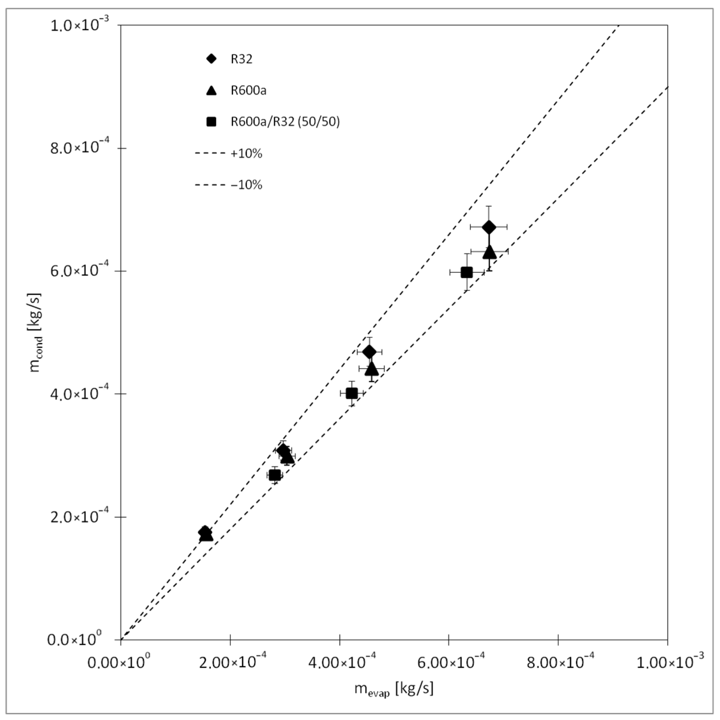
The reliability of the experimental setup is verified by performing heat balance calculations for the evaporator and condenser, in which mass flows are obtained with Equations (4) and (5) and then compared, as shown in Figure 2. The maximum uncertainty in the mass flow is 5.5%. The deviation is related to the calculation method employing heat balance and results from the uncertainties in calculating the enthalpies. The mean absolute deviation (MAD) is 3.7%, proving the reliability of the experimental setup.

3.2. Working Conditions of the TPTL Operating with Zeotropic Mixture

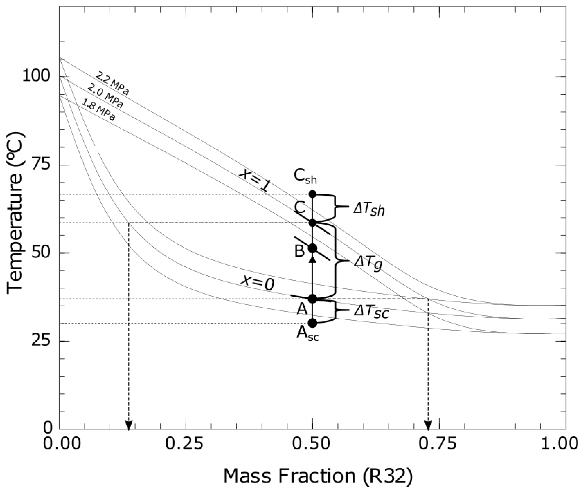
TPTLs employing pure fluids are well known and documented, as indicated in the literature overview. However, the information on the working conditions of TPTL using zeotropic mixtures as working fluids is lacking. Therefore, using Figure 3, presenting a T-x diagram, the working principle is explained, taking the saturation pressure of 2 MPa as a basis. The refrigerant, consisting of R600a and R32 with the composition of 50% of each compound, enters the evaporator section at its saturation conditions, denoted as A, located at the bubble line curve with the vapor quality x = 0 . Subcooling of the liquid may occur in the condenser, resulting in the liquid temperature being lower than the saturation temperature (Asc). The first bubble, generated at the temperature of 37 °C, has the composition of 0.73 of the more volatile compound R32 and 0.27 of the less volatile R600a. Then, the evaporation follows, reaching a virtual condition of B, situated in the wet vapor area ( 0 < x < 1 ) . Further evaporation continues until condition C, at the dew curve with vapor quality x = 1 , is attained with the temperature of 59 °C. If heated further, the saturated vapor at C will become superheated (Csh). The last drop of the liquid refrigerant at state C has the composition of 0.14 of R32. To sum up, the vapor leaving the evaporator section may be wet vapor, saturated vapor, or superheated vapor, depending on the heat and mass fluxes and the filling ratio of the TPTL.
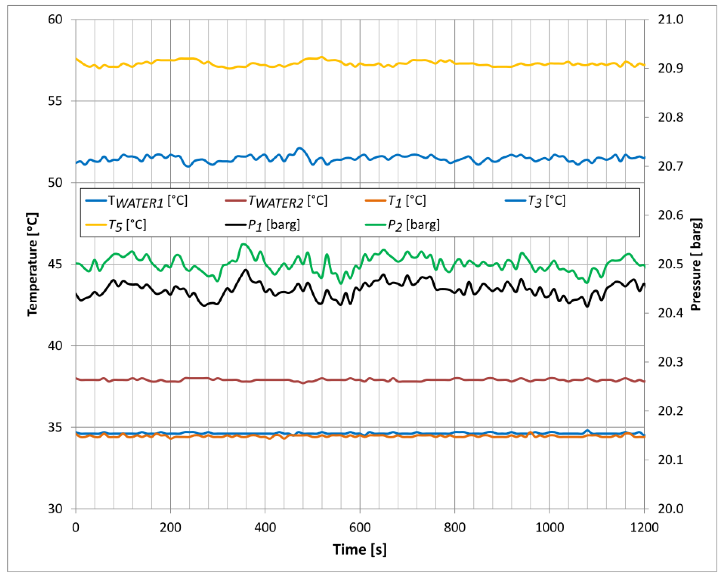
Figure 4 presents the working conditions of the loop thermosyphon with R600a/R32 mixture under steady state. Since the TPTL operates periodically, small oscillations may be noticed, but the changes should be considered negligible. The pressures are within 20.5 barg, with the pressure P2 being higher than P1 due to the liquid column height, which is considered the driving force of the TPTL. The temperature T5 of the vapor leaving the evaporator is high, being 57.5 °C, which is close to the dew point temperature of the examined mixture. This phenomenon is explained in detail in Figure 3. The refrigerant mixture of R600a/R32 exhibits a non-isothermal phase change process during the evaporation in the evaporator section with a very high temperature shift/glide of 22 K, allowing for the operation under high outlet vapor temperatures. This feature is also the main advantage of the proposed solution, since, despite the high leaving vapor temperature, there is boiling inside the evaporator, providing efficient heat removal. The working operation can be regarded as stable, taking into account that a zeotropic mixture with a high-temperature glide is employed.

3.3. Thermal Performance Under Varying Heat Loads and Condensing Temperatures

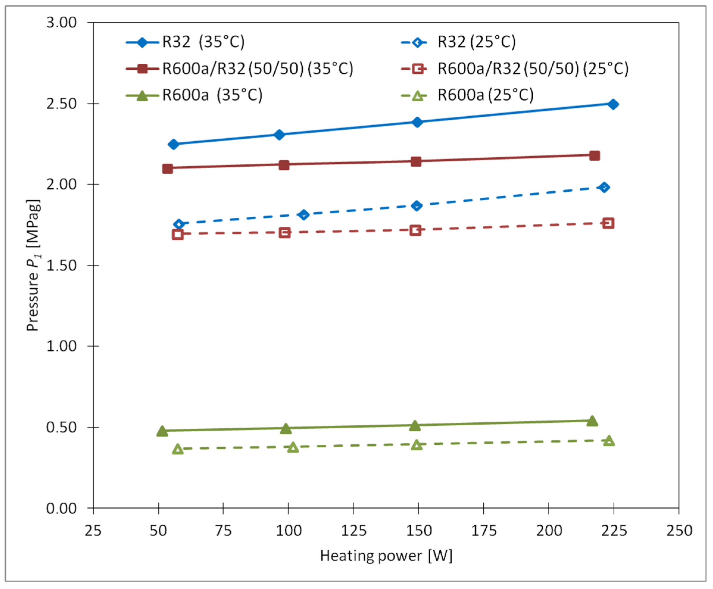
Figure 5 presents the condensing pressure under increasing heat load on the evaporator. The highest values are obtained with R32 with a cooling-water temperature of 35 °C, reaching 2.25 to 2.50 MPa (g) with 50 and 225 Watts, respectively. With the mixture of R600a/R32 (50%/50%), the pressure ranges from 2.10 to 2.18 MPa (g) under the corresponding heat loads and water temperatures. Refrigerant R600a exhibits the lowest pressure, being 0.48 to 0.54 MPa (g). When the cooling-water temperature is set at 25 °C, the pressure is 1.76 to 1.99 MPa (g) for R32, 1.70 to 1.76 with R600a/R32 (50%/50%), and 0.37 to 0.43 MPa (g) with R600a. The lower the cooling-water temperature is, the lower the condensing pressure is as a result of the decreasing saturation pressure of the working fluid. An increase in the condensing pressure of approx. 11 to 14% may be noticed for pure R32 and R600a with increasing heat load, while a much lower value of about 3.5% is observed for the mixture of R600a/R32. The zeotropic mixture of R600a/R32 (50%/50%) exhibits a significant temperature glide ΔTg of 22.3 K at the pressure of 2 MPa, as shown in Figure 3, during the condensation that leads to an increased mean temperature difference across the condenser, thus resulting in higher condenser performance and lower pressure rise under increasing heat duty.
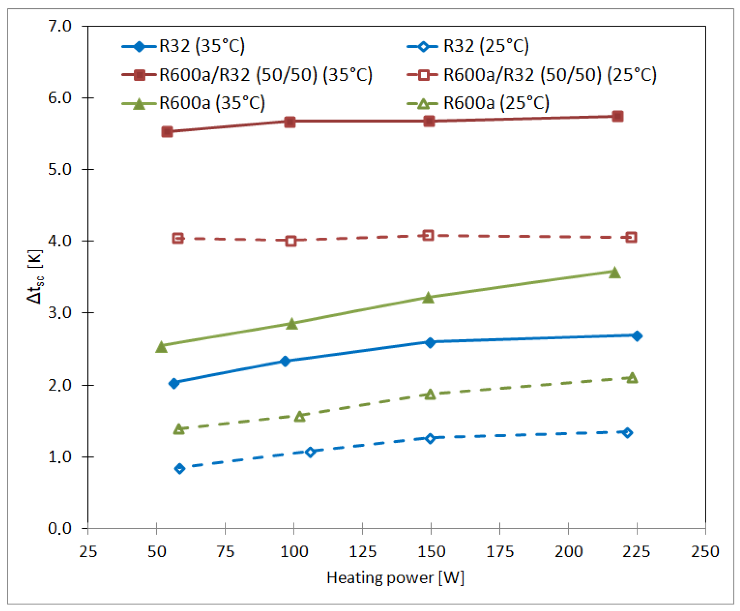
The degree of subcooling is shown in Figure 6. The phenomenon of subcooling is explained in detail in Figure 3. It is defined as the difference in temperature between the liquid leaving the condenser and its saturation temperature at the bubble point for a given pressure. The highest and constant values of 4 to 5 K are obtained with R600a/R32 under both water temperatures of 35 and 25 °C. With R600a and R32, the values are lower, reaching 0.8 to 1.3 with R32 and 1.4 to 2.1 with R600a under 25 °C water temperature. When the water temperature was 35 °C, the subcooling was in the range of 2.0 to 2.7 K for R32 and 2.5 to 3.6 K with R600a. As mentioned earlier, a higher logarithmic mean temperature difference (LMTD) across the condenser with a zeotropic mixture leads to favorable condensing conditions, resulting in higher subcooling values.
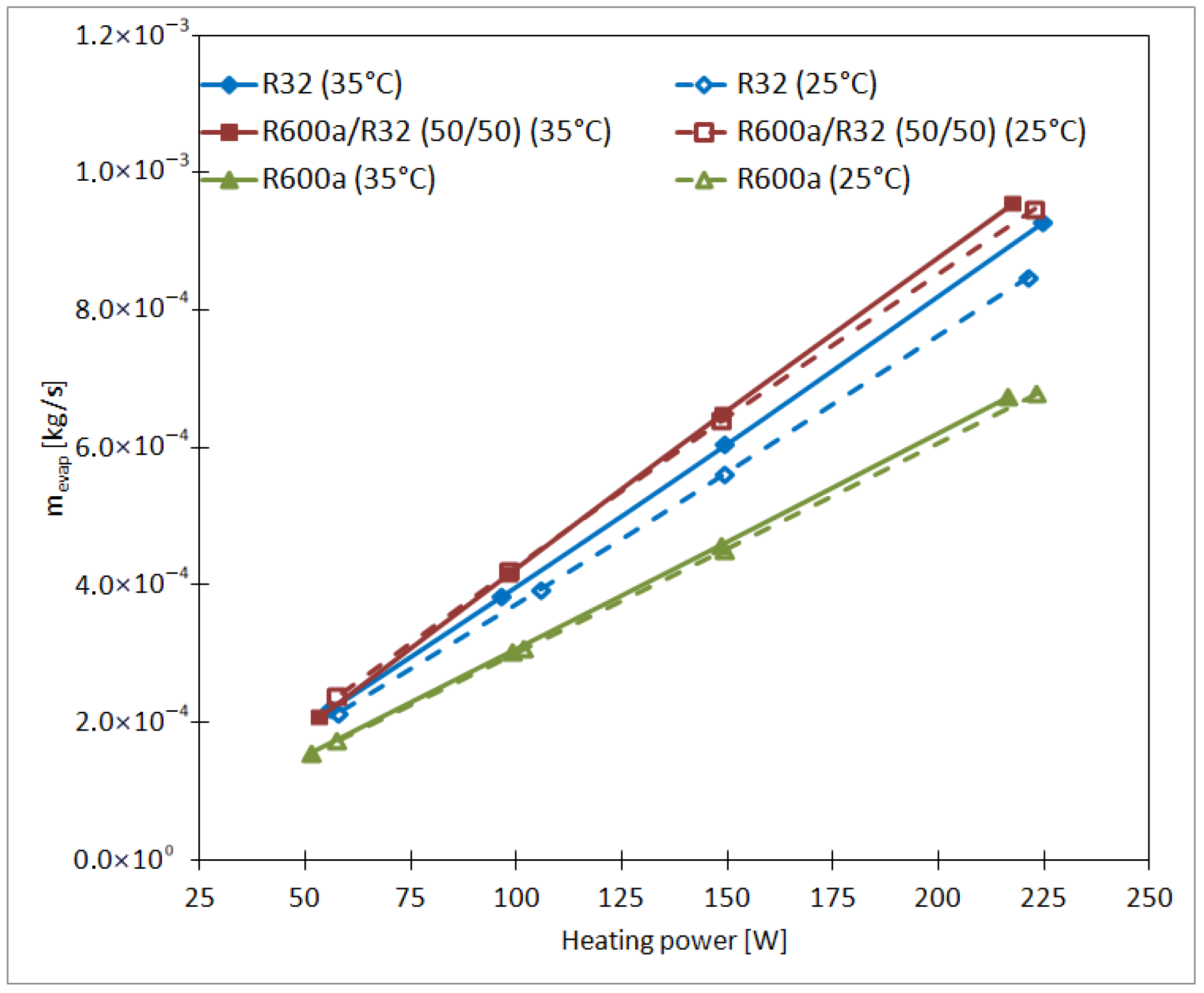
The evaporator mass flow under different heat loads is shown in Figure 7. It can be noticed that the mass flow increases gradually with the increasing heat load, which is due to the self-balancing phenomena of TPTL. Since more heat is transferred to the evaporator section, more vapor is produced, increasing the condensation rate in the condenser and increasing the refrigerant mass flow. The mass flow is directly proportional to the amount of heat load. For example, with a 4.4-times heat load increase from 50 to 220 W for R600a, the mass flow changes from 1.56 × 10 4 to 6.74 × 10 4 kg/s, being 432% of the original value. The highest mass flows are observed for the mixture of R600a/R32, followed by pure R32 and then R600a, resulting from the different heat levels examined during vaporization. When the inlet temperature changes from 25 to 35 °C, the mass flow increases slightly, with higher values for 35 °C as a result of heat balance and mass transfer due to the decreasing vaporization heat of the working fluid. Hydrocarbon refrigerants, i.e., R600a, exhibit a higher vaporization heat than most fluorocarbons, i.e., R32. For this reason, the mass flow with R600a is lower than with R32. With R600a/R32, the mass flow is the highest, which may be a result of wet vapor leaving the evaporator section, meaning that not all the liquid evaporates, as indicated by leaving-vapor qualities lower than 1, as presented in Table 3. With pure fluids, R600a and R32, saturated or superheated vapor were present at the evaporator outlet, as a result of a uniform fluid temperature distribution during the evaporation process.
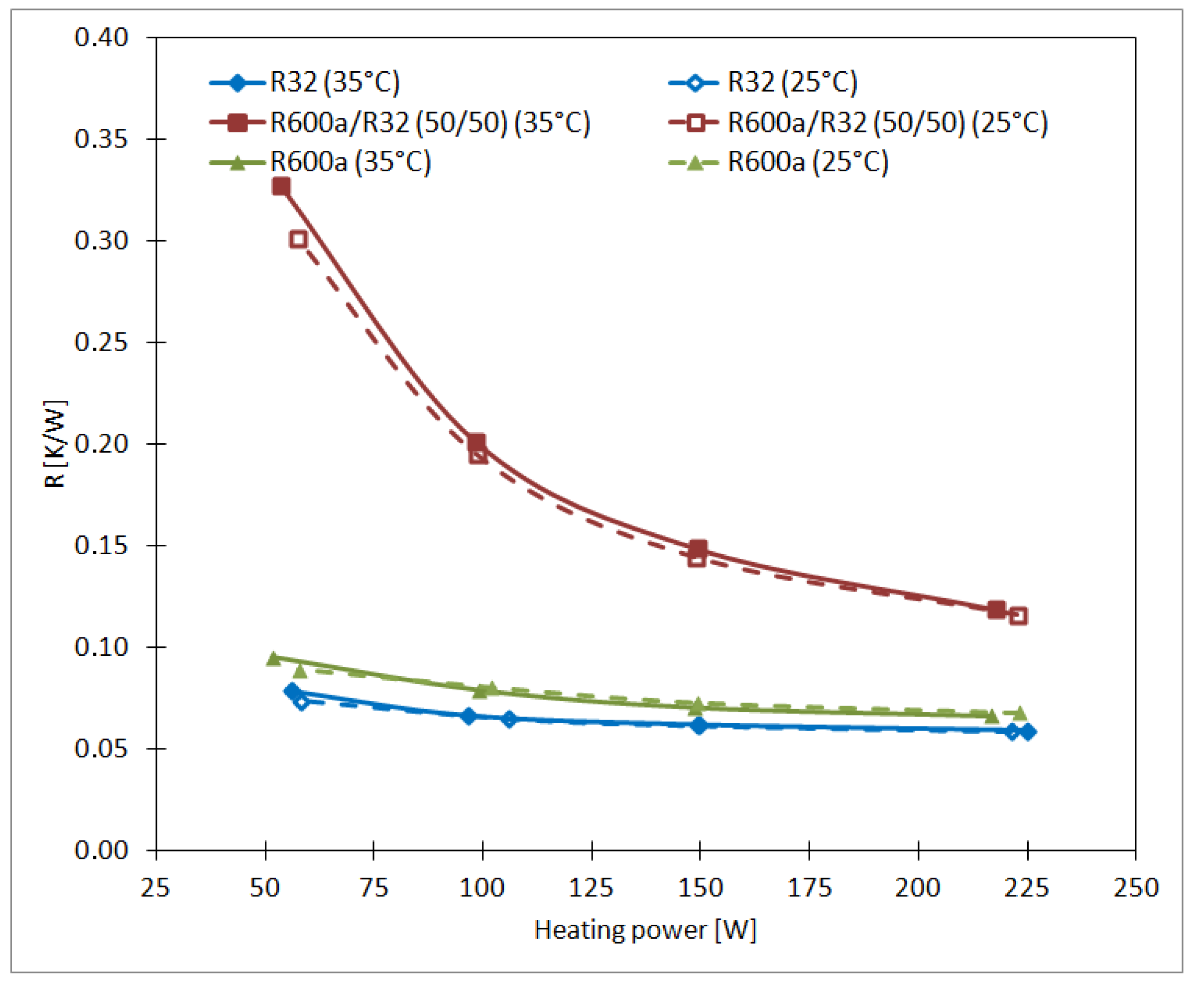
Thermal resistance is one of the most common parameters used to describe the heat transfer ability of TPTL. With lower thermal resistance, more heat may be transferred for a given driving-temperature difference. Figure 8 presents the experimental results. When R600a/R32 is used, the thermal resistance is the highest, ranging from 0.3009 to 0.1186 K/W. For pure fluids, the thermal resistance varies from 0.0663 to 0.0952 K/W for R600a and from 0.0787 to 0.0590 K/W for R32. The water inlet temperature presented no significant effect on the thermal resistance. The obtained results are well correlated with those presented in the literature. Naresh et al. [26] reported a thermal resistance ranging from 0.3 to 0.1 K/W for a thermosyphon working with acetone, while Liu et al. [14] obtained values of 0.4 to 0.12 with R134a under a condensing temperature of 10 °C and heat loads from 50 to 275 W.

3.4. Boiling-Heat Transfer Coefficient

Thermophysical properties of the refrigerant (i.e., viscosity, heat of vaporization, gas and liquid densities), along with heat and mass fluxes [4,32], are the main parameters affecting the boiling-heat transfer coefficient. With an appropriate wall superheat, the refrigerant bubbles start to form at nucleation sites, generating vapor flow through the evaporator. It is known that an increase in the heat flux causes more nucleation sites, thus inducing the bubble generation rate, which also leads to higher flow rates in thermosyphons. Due to the higher flow rates and more uniform flow, the heat transfer coefficients are reported to increase [5].
Pool boiling and flow boiling are the main modes of heat transfer in thermosyphon evaporators. In this experiment, the boiling-heat transfer is measured and compared against well-known empirical correlations, as presented in Table 4.
Obtained values are evaluated using mean absolute deviation and root mean square. Cooper’s equation, which is established for pool boiling, overpredicts the actual values by 131% to 428% with very high total relative errors ranging from 1.317 to 4.396. With the Arora equation, which was developed for flow boiling, the overshoot reaches 28 to 70% with total relative errors of 0.331 to 0.889. These values could not be regarded as satisfactory; however, with some tuning of the coefficients, the Arora equation could possibly provide more accurate predictions. Taking the Imura equation with its original power exponent, n = 0.4 , the obtained values for MAD and RMS are 101% to 291% and 1.172 to 3.102, respectively.
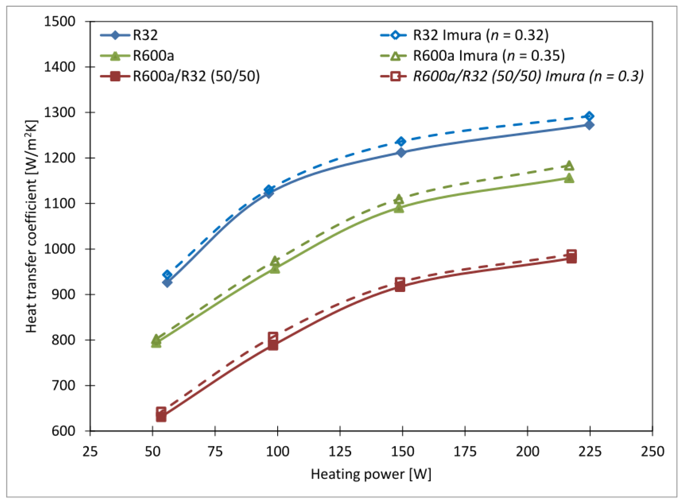
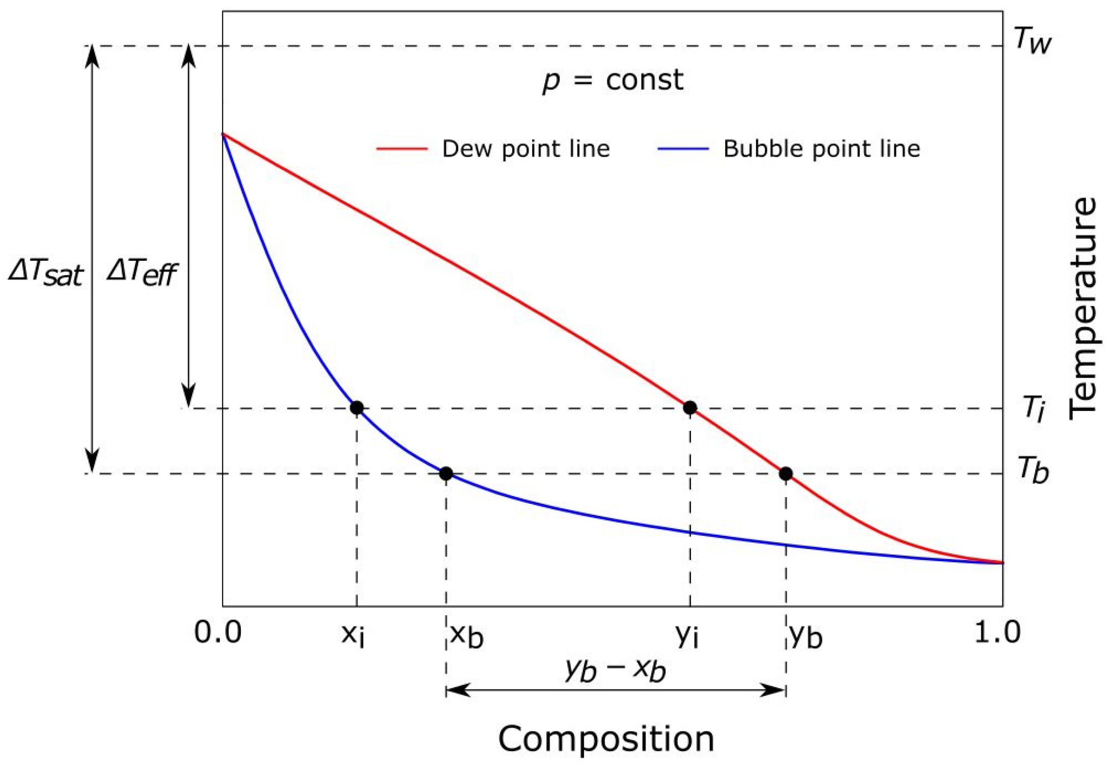
Figure 9 presents the experimental and calculated values. A modified Imura equation, with original power exponents n = 0.4 modified to n ¯ = 0.32 for R32, n ¯ = 0.35 for R600a, and n ¯ = 0.3 for R600a/R32, presents satisfactory results, as indicated in Table 3, providing an MAD of 1.5% to 1.7% and RMS of 0.016 to 0.018. The boiling-heat transfer increases with the heat load, more specifically with an increasing heat flux. The highest values, reaching 1273 W/m2 K, are obtained with R32, followed by R600a with a maximum of 1156 W/m2 K. Ma et al. [35] reported that the boiling-heat transfer coefficients in a closed thermosyphon reached 750 to 1100 W/m2 K for the pure refrigerants, R600a and R134a, at the saturation temperature of 40 °C. Ding et al. [4] obtained higher values of 2500 to 4200 W/m2 K with R410A, under similar heat fluxes but with much higher mass fluxes, resulting from the smaller cross-sectional area of the evaporator. Gil and Fijałkowska [11] examined pool-boiling-heat transfer coefficients for R600a, obtaining values of 700 to 1500 W/m2 K, for the corresponding heat fluxes from 5 to 10 kW/m2. According to Rohsenow’s theory, boiling-heat transfer is strictly related to heat flux and the liquid’s turbulence, which is generated by bubbles formed at the heating surface. The bubble departure diameter can be obtained with Equation (13). The resulting bubble diameters for the fluids studied are reported in Table 3. It can be noted that the smallest bubbles are observed for R32, while the largest are observed for R600a. The lowest surface tension is exhibited by R32, which results in many small-diameter bubbles, enhancing the turbulence and the heat transfer itself. The zeotropic mixture of R600a/R32 showed the lowest heat transfer values, ranging from 630 to 980 W/m2 K. Figure 10 presents the particular parameters influencing the heat transfer in mixtures. Due to the mass transfer resistance (yb − xb) and the loss of available superheat (ΔTeff vs. ΔTsat), which is related to the bulk composition, the boiling-heat transfer coefficients for zeotropic mixtures are usually found to be lower than those for pure refrigerants [36]. Recently, Chen at al. [25] reported that in TPTL, the evaporation heat transfer with pure R134a was higher by 48.3% compared with the zeotropic mixture of R407C.
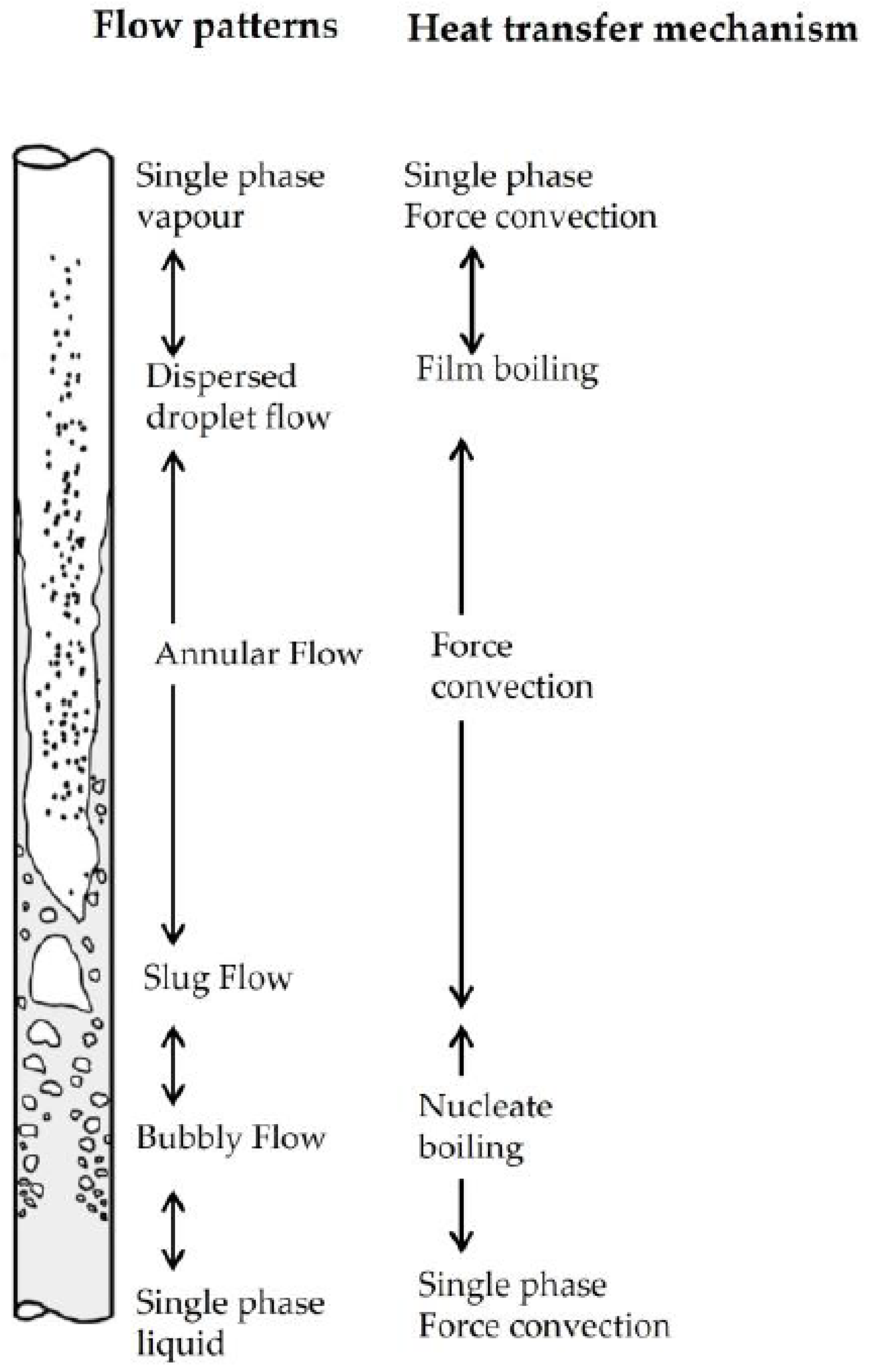
With a sight glass installed in the middle of the evaporator, slow-motion recordings are performed in this experiment. The screenshots are shown in Figure 11. Different flow regimes may be observed. Starting with Figure 11a—R32 with 50 W heat load, small and larger bubbles of circular form are present, which may be regarded as bubbly to slug flow, as illustrated in Figure 12. The flow velocity is low as a result of low heat and mass fluxes of q = 3.2   k W / m 2 and G = 2.27   k g / ( m 2 s ) , respectively. With a higher heat load of 225 W, the corresponding q = 12.9   k W / m 2 , and G = 9.59   k g / ( m 2 s ) , the flow transforms to annular flow with many very small bubbles, as shown in Figure 11b. The flow patterns with R600a/R32 are shown in Figure 11c,d. The patterns are similar to those of R32, but larger and oval bubbles are formed.
There is a strict correlation between observed flow patterns and obtained heat transfer coefficients. due to different heat transfer mechanisms, as shown in Figure 12. With low heat and mass fluxes, single-phase convection and nucleate boiling are predominant. With increasing velocity, there is a flow transition into annular flow with very small bubbles present; thus, an increase in the heat transfer rate is observed. The results are comparable with those obtained with R22 by Ding et al. [5]. It should be noted that both heat and mass fluxes, along with the thermophysical properties of the refrigerant, should be taken into account when examining boiling-heat transfer in TPTLs.

4. Discussion

An experimental evaluation of the two-phase loop thermosyphon is performed. The effects of the refrigerant, cooling-water inlet temperature, and heat load are examined. A novel low-GWP mixture of R600a/R32 is employed in a thermosyphon loop for the first time.
The cooling-water inlet temperature affects system parameters. With an increase in the water inlet temperature, the condensing pressure increases as a result of increasing saturation pressure of the working fluid. The highest values, reaching 2.25 to 2.50 MPa (g), are obtained with R32 with a cooling-water temperature of 35 °C. The condensing pressure with the mixture of R600a/R32 (50%/50%) is lower, ranging from 2.10 to 2.18 MPa (g) under the same temperature conditions.
Increasing the heat load causes a rise in the condensing pressure of approx. 11 to 14% for pure R32 and R600a, while a much smaller increase of 3.5% is observed for the mixture of R600a/R32. The zeotropic mixture of R600a/R32 (50%/50%) exhibits a significant temperature glide during the condensation, which leads to an increased mean temperature difference across the condenser, thus resulting in higher condenser performance and lower-pressure rise under increasing heat duty. The highest liquid subcooling is obtained with R600a/R32.
Thermal resistance of the thermosyphon loop is a key parameter for the valuation of its performance. For pure fluids, the thermal resistance varies from 0.0952 to 0.663 K/W for R600a and from 0.0787 to 0.0590 K/W for R32. The thermal resistance with R600a/R32 is the highest, ranging from 0.3009 to 0.1186 K/W. Thermal resistance is strictly related to the mass flux of the working fluid, as it affects the internal heat transfer resistance of both the condenser and the evaporator. The self-balancing phenomenon of TPTL is observed. The mass flow is directly proportional to the amount of heat load, since when more heat is transferred to the evaporator section, more vapor is produced, which improves the condensation rate in the condenser and increases the refrigerant mass flow.
Since heat transfer in the evaporator induces the flow of the working medium in the TPLT, the flow-boiling-heat transfer is measured in this experiment. The results are compared against well-known empirical correlations. The boiling-heat transfer increases with the heat load, more specifically with increasing heat flux. The highest values are obtained with R32, while the lowest are with R600a/R32. The Imura equation, with modified power exponents, presents satisfactory results for the prediction of boiling-heat transfer coefficients.
Although a thorough literature study was conducted, no previous use of a zeotropic mixture with a high-temperature glide in TPLT was found. Considering this fact, this is the first time a mixture (R600a/R32) with a high-temperature glide of 22 K was employed in a loop thermosyphon. The studied zeotropic mixture of R600a/R32 provided the highest vapor temperature of 59.5 °C at the evaporator outlet, which may be beneficial in heat reclaim systems. A high vapor temperature also promotes the condenser performance and may lead to a decrease in the required condenser heat exchange surface, reducing the cost of the equipment.
Employing a mixture of R600a/R32 may be a trade-off since it provides a high-temperature vapor, which is beneficial. However, contrary to that, its heat transfer rates are the lowest, as indicated by low boiling-heat transfer and high thermal resistance of the loop. Further investigations of TPLTs working with environmentally friendly fluids are needed.

Supplementary Materials

The following supporting information can be downloaded at https://www.mdpi.com/article/10.3390/chemengineering9060131/s1.

Author Contributions

Conceptualization, M.S. and D.K.; methodology, M.S. and D.K.; software, M.S.; validation, M.S. and D.K.; formal analysis, M.S.; investigation, M.S., D.K., M.K. and F.K.; resources, M.S.; data curation, M.S., DK., M.K. and F.K.; writing—original draft preparation, M.S.; writing—review and editing, M.S.; visualization, M.S.; supervision, M.S. and D.K.; project administration, M.S.; funding acquisition, M.S. All authors have read and agreed to the published version of the manuscript.

Funding

Research was funded by Warsaw University of Technology within the Excellence Initiative: Research University (IDUB) program.

Data Availability Statement

The original contributions presented in this study are included in the article/Supplementary Material. Further inquiries can be directed to the corresponding author.

Acknowledgments

The authors gratefully acknowledge the support provided by Sanhua International Europe S.L. The authors are grateful to Adam Dłużniewski of Sanhua International Europe S.L.

Conflicts of Interest

The authors declare no conflicts of interest.

References

  1. Ding, T.; He, Z.G.; Hao, T.; Li, Z. Application of separated heat pipe system in data center cooling. Appl. Therm. Eng. 2016, 109, 207–216. [Google Scholar] [CrossRef]
  2. Yang, S.; Guo, X.; Xu, H.; Tang, F.; Zhang, B.; Zhang, Y. Experimental studies on the heat transfer characteristics and instability of a loop thermosyphon with a vertical flat evaporator for IGBT heat dissipation. Appl. Therm. Eng. 2025, 264, 125524. [Google Scholar] [CrossRef]
  3. Zhang, P.; Wang, B.; Wu, W.; Shi, W.; Li, X. Heat recovery from internet data centers for space heating based on an integrated air conditioner with thermosyphon. Renew. Energy 2015, 80, 396–406. [Google Scholar] [CrossRef]
  4. Ding, T.; Wen Cao, H.; Guang He, Z.; Li, Z. Boiling heat transfer characteristics of the R744 coolant in the evaporator of the separated heat pipe system. Int. J. Heat. Mass. Transf. 2017, 113, 1254–1264. [Google Scholar] [CrossRef]
  5. Ding, T.; Cao, H.W.; He, Z.G.; Li, Z. Visualization experiment on boiling heat transfer and flow characteristics in separated heat pipe system. Exp. Therm. Fluid. Sci. 2018, 91, 423–431. [Google Scholar] [CrossRef]
  6. Zou, S.; Zhang, Q.; Yue, C.; Wang, J.; Du, S. Study on the performance and free cooling potential of a R32 loop thermosyphon system used in data center. Energy Build. 2022, 256, 111682. [Google Scholar] [CrossRef]
  7. Tong, Z.; Ding, T.; Li, Z.; Liu, X.H. An experimental investigation of an R744 two-phase thermosyphon loop used to cool a data center. Appl. Therm. Eng. 2015, 90, 362–365. [Google Scholar] [CrossRef]
  8. Başaran, A. Experimental investigation of R600a as a low GWP substitute to R134a in the closed-loop two-phase thermosyphon of the mini thermoelectric refrigerator. Appl. Therm. Eng. 2022, 211, 118501. [Google Scholar] [CrossRef]
  9. Lemmon, E.W.; Huber, M.L.; McLinden, M. NIST Reference Fluid Thermodynamic and Transport Properties—REFPROP; Version 8.0; National Institute of Standards and Technology: Gaithersburg, MD, USA, 2007.
  10. Calm, J.; Hourahan, G. Refrigerant data update. HPAC Eng. 2007, 79, 50–64. Available online: http://www.hourahan.com/wp/wp-content/uploads/2010/08/2007-Refrig-Update.pdf (accessed on 26 August 2025).
  11. Gil, B.; Fijałkowska, B. Experimental study of nucleate boiling of flammable, environmentally friendly refrigerants. Energies 2019, 13, 160. [Google Scholar] [CrossRef]
  12. Tong, Z.; Liu, X.H.; Li, Z.; Jiang, Y. Experimental study on the effect of fill ratio on an R744 two-phase thermosyphon loop. Appl. Therm. Eng. 2016, 99, 302–312. [Google Scholar] [CrossRef]
  13. Tong, Z.; Liu, X.H.; Jiang, Y. Experimental study of the self-regulating performance of an R744 two-phase thermosyphon loop. Appl. Energy 2017, 186, 1–12. [Google Scholar] [CrossRef]
  14. Liu, Y.; Li, Z.; Li, Y.; Jiang, Y.; Tang, D. Heat transfer and instability characteristics of a loop thermosyphon with wide range of filling ratios. Appl. Therm. Eng. 2019, 151, 262–271. [Google Scholar] [CrossRef]
  15. Das, K.M.; Guha, A.; Ramgopal, M. Quantitative assessment of various low-GWP zeotropic mixtures of CO2 as the working fluid in two-phase natural circulation loops. Appl. Therm. Eng. 2025, 266, 125512. [Google Scholar] [CrossRef]
  16. Wang, H.; Bao, Y.; Zhu, S.; Liu, M.; Rao, Z. Experimental research on heat transfer performance of CO2 low temperature heat pipe. Int. J. Heat. Mass. Transf. 2021, 170, 120987. [Google Scholar] [CrossRef]
  17. Tong, Z.; Wang, W.; Wang, P.; Han, Z.; Yu, H.; Hu, S. Effect of valve regulation on the operating state of a CO2 two-phase thermosyphon loop. Case Stud. Therm. Eng. 2025, 69, 106055. [Google Scholar] [CrossRef]
  18. Tong, Z.; Zhu, Z.; Wang, W.; Han, Z. Impact of flow resistance on the operational stability of two-phase thermosyphon loop with different working fluids. Therm. Sci. Eng. Prog. 2025, 60, 103463. [Google Scholar] [CrossRef]
  19. Hu, J.; He, Y.; Wang, X.; Liu, J.; Liu, B.; Liu, L. Experimental study on the loop thermosyphon cooling system for IGBT in high-speed trains. Appl. Therm. Eng. 2025, 274, 126613. [Google Scholar] [CrossRef]
  20. Qu, J.; Zhao, Y.; Hua, Y.; Yang, W.; Gao, S. Comparative study of operational characteristics for two-phase loop thermosyphons with and without pump assistant: Heat transfer performance and high-speed visualization observation. Appl. Therm. Eng. 2025, 271, 126382. [Google Scholar] [CrossRef]
  21. Corigliano, O.; Algieri, A.; Fragiacomo, P. Turning Data Center Waste Heat into Energy: A Guide to Organic Rankine Cycle System Design and Performance Evaluation. Appl. Sci. 2024, 14, 6046. [Google Scholar] [CrossRef]
  22. Zhao, S.C.; Zhang, Z.; Zhao, R.; Wu, T.; Zhang, X.; Liu, Z.C.; Liu, W. An R1234ze(E) loop heat pipe with flat-plate evaporator for cooling electronic devices. Therm. Sci. Eng. Prog. 2023, 42, 101935. [Google Scholar] [CrossRef]
  23. Marcinichen, J.B.; Olivier, J.A.; Thome, J.R. On-chip two-phase cooling of datacenters: Cooling system and energy recovery evaluation. Appl. Therm. Eng. 2012, 41, 36–51. [Google Scholar] [CrossRef]
  24. Brendel, L.P.M.; Bernal, S.N.; Widmaier, P.; Roskosch, D.; Arpagaus, C.; Bardow, A.; Bertsch, S.S. High-glide refrigerant blends in high-temperature heat pumps: Part 1—Coefficient of performance. Int. J. Refrig. 2024, 165, 84–96. [Google Scholar] [CrossRef]
  25. Chen, X.; Ding, T.; Wang, X.; Li, Z. Research on energy saving potentials using pure and zeotropic refrigerants in data center cooling systems. Case Stud. Therm. Eng. 2024, 57, 104324. [Google Scholar] [CrossRef]
  26. Naresh, Y.; Balaji, C. Experimental investigations of heat transfer from an internally finned two phase closed thermosyphon. Appl. Therm. Eng. 2017, 112, 1658–1666. [Google Scholar] [CrossRef]
  27. Long, Z.Q.; Zhang, P. Heat transfer characteristics of thermosyphon with N2-Ar binary mixture working fluid. Int. J. Heat. Mass. Transf. 2013, 63, 204–215. [Google Scholar] [CrossRef]
  28. Guichet, V.; Almahmoud, S.; Jouhara, H. Nucleate pool boiling heat transfer in wickless heat pipes (two-phase closed thermosyphons): A critical review of correlations. Therm. Sci. Eng. Prog. 2019, 13, 100384. [Google Scholar] [CrossRef]
  29. Liu, Z.; Winterton, R.H.S. A general correlation for saturated and subcooled flow boiling in tubes and annuli, based on a nucleate pool boiling equation. Int. J. Heat. Mass. Transf. 1991, 34, 2759–2766. [Google Scholar] [CrossRef]
  30. Imura, H.; Kusuda, H.; Ogata, J.-I.; Miyazaki, T.; Sakamoto, N. Heat Transfer in Two-Phase Closed-Type Thermosyphons. Heat. Transf. Jpn. Res. 1979, 45, 712–722. [Google Scholar]
  31. Louahlia-Gualous, H.; Le Masson, S.; Chahed, A. An experimental study of evaporation and condensation heat transfer coefficients for looped thermosyphon. Appl. Therm. Eng. 2017, 110, 931–940. [Google Scholar] [CrossRef]
  32. Arora, C.P. Refrigeration and Air Conditioning; McGraw Hill Education: Noida, India, 2009. [Google Scholar]
  33. Ding, T.; Cao, H.W.; He, Z.G.; Li, Z. Experiment research on influence factors of the separated heat pipe system, especially the filling ratio and Freon types. Appl. Therm. Eng. 2017, 118, 357–364. [Google Scholar] [CrossRef]
  34. Ling, L.; Zhang, Q.; Yu, Y.; Liao, S.; Sha, Z. Experimental study on the thermal characteristics of micro channel separate heat pipe respect to different filling ratio. Appl. Therm. Eng. 2016, 102, 375–382. [Google Scholar] [CrossRef]
  35. Ma, L.; Shang, L.; Zhong, D.; Ji, Z. Experimental investigation of a two-phase closed thermosyphon charged with hydrocarbon and Freon refrigerants. Appl. Energy 2017, 207, 665–673. [Google Scholar] [CrossRef]
  36. Park, K.J.; Jung, D. Nucleate boiling heat transfer coefficients of mixtures containing propane, isobutane and HFC134a. J. Mech. Sci. Technol. 2006, 20, 399–408. [Google Scholar] [CrossRef]
  37. Hernaiz, M.; Elexpe, I.; Aranzabe, E.; Aguayo, A.T. Flow Boiling Heat Transfer; Experimental Study of Hydrocarbon Based Nanorefrigerant in a Vertical Tube. Nanomaterials 2023, 13, 2230. [Google Scholar] [CrossRef] [PubMed]
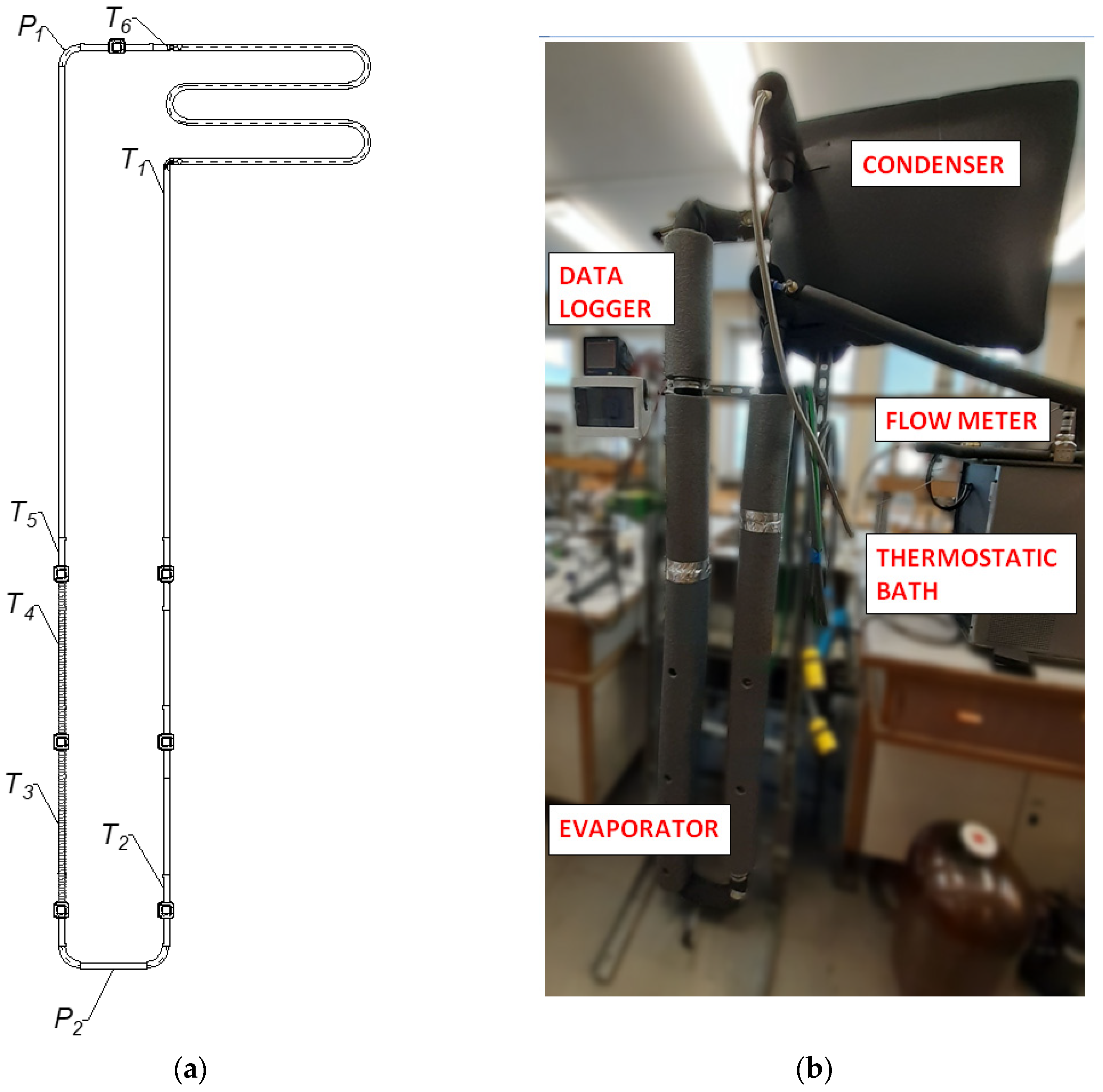
Figure 1. Thermosyphon system: (a) schematic diagram: T-fluid temperatures, T3 and T4—evaporator wall temperatures, P—pressures; (b) experimental stand.
Chemengineering 09 00131 g001
Figure 2. Comparison of mass flows through evaporator and condenser for experimental setup verification.
Chemengineering 09 00131 g002
Figure 3. T-x diagram of R600a/R32 mixture.
Chemengineering 09 00131 g003
Figure 4. Working conditions of R600a/R32 mixture at 150 W heat load.
Chemengineering 09 00131 g004
Figure 5. Influence of heat load and condensing temperature on condensing pressure.
Chemengineering 09 00131 g005
Figure 6. Influence of heat load and condensing temperature on subcooling degree.
Chemengineering 09 00131 g006
Figure 7. The influence of heat load and condensing temperature on evaporator mass flow.
Chemengineering 09 00131 g007
Figure 8. The influence of heat load and condensing temperature on thermal resistance.
Chemengineering 09 00131 g008
Figure 9. Experimental and calculated boiling-heat transfer coefficients.
Chemengineering 09 00131 g009
Figure 10. Factors influencing the mixture’s boiling-heat transfer.
Chemengineering 09 00131 g010
Figure 11. Boiling flow patterns: (a) R32 with heat load of 50 W; (b) R32 with 225 W; (c) R600a/R32 with 50 W; (d) R600a/R32 with 225 W.
Chemengineering 09 00131 g011
Figure 12. Flow-boiling patterns [37].
Chemengineering 09 00131 g012
Table 1. Summary of experimental uncertainties.
ParameterInstrumentUncertainty
TemperaturePt100 M222 A class resistor (Heraeus, Hanau, Germany)±0.1 K
Pressure0–3 MPa pressure transducer (Sanhua, Shaoxing, China)±0.015 MPa
PowerF&F LE-01MR power transducer (F&F, Pabianice, Poland)±2 W
Table 2. Refrigerant charge, density, and filling ratio.
RefrigerantMass [kg]Density [kg/m3]Volume [m3]FR
R320.15981.40.0001531.01
R600a0.0858556.90.0001541.02
R600a/R32 (50/50)0.1024657.10.0001561.03
Table 3. Temperatures, vapor qualities, and bubble departure diameter at the evaporator outlet at cooling water at 35 °C.
-T5xd0T5xd0T5ΔTshd0
-R600aR600a/R32R32
22540.61.01.2858.00.870.8340.200.74
15038.51.01.2957.20.870.8338.100.76
10037.11.01.3057.50.890.8446.59.30.77
5535.81.01.3159.50.970.9350.614.40.78
Table 4. Mean absolute deviation (MAD) and root mean square (RMS) of experimental and calculated boiling-heat transfer coefficients.
-MADRMSMADRMSMADRMS
RefrigerantR600aR32R600a/R32
Imura1.0141.1722.9143.1021.3891.394
Imura n0.0170.0180.0150.0160.0150.016
Cooper1.3171.4172.8603.0344.2764.396
Arora0.2820.3310.5470.7140.7020.889
Disclaimer/Publisher’s Note: The statements, opinions and data contained in all publications are solely those of the individual author(s) and contributor(s) and not of MDPI and/or the editor(s). MDPI and/or the editor(s) disclaim responsibility for any injury to people or property resulting from any ideas, methods, instructions or products referred to in the content.