Abstract
The majority of downhole monitoring methods currently available for well cement projects, which are used to assess the quality of cement placement and monitor well integrity over time, are primarily qualitative in nature and rely on surface signs. Obviously, there is a need for a practical quantitative downhole monitoring method to ensure proper cement placement and long-term performance. One potential resolution to address this enduring problem would involve enhancing the designs of the cement slurry and transforming the cement into durable downhole logging equipment, thereby facilitating real-time observation of operations. To address this issue, in this work, carboxylated styrene butadiene rubber (XSBR) polymer-treated cement was used to understand the gas migration and fluid loss mechanism. The experimental findings indicate that the electrical resistivity of polymer-treated cement is significantly influenced by applied loads and stresses. The unconfined compressive strength test with XSBR-blended cement showed a significant improvement from 22.5 MPa to 33.31 MPa when XSBR increased from 0% to 3%. Additionally, in the high pressure and high temperature (HPHT) chamber, the latex polymer used as a migration additive control, the total fluid loss is found to be about 59.2 mL under 30 min of testing. Also, to emulate the accuracy, nonlinear predictive models based on the resistivity index correlation were developed to forecast polymer-treated cement performance for all the tests performed in this study. Hence, the utilization of polymer-treated cement systems proves to be a valuable method for monitoring the placement and post-placement performance of cement, as well as for visualizing real-time operational issues associated with cementing. This will also allow operators to provide immediate solutions, saving time and operational costs.
1. Introduction
A crucial phase in the building of any well is cementing. It entails adhering the well casing to the surrounding geological structure by placing cement slurry between them. In addition to sealing off intricate formations and preventing the unintended movement of water, gas, and oil, this covering gives the casing structural strength [1,2]. Strong corrosion resistance is required of the cement slurry in wells containing CO2 [3]. The main constituents of oil well cement is tricalcium silicate (C3S), dicalcium silicate (C2S), tricalcium aluminate (C3A), and tetra calcium aluminoferrite (C4AF). These constituents hydrate to generate calcium hydroxide (CH) and calcium silicate hydrate (CSH), which are important sources of alkalinity and strength [4]. In acidic conditions, the cement is vulnerable to corrosion caused by CO2 because of the high alkalinity caused by CH [5]. When these substances are hydrated, they yield the alkaline CH and CSH [5]. These alkaline chemicals readily react with the acidic fluids produced by CO2, which weakens the cement’s mechanical properties. Cement high alkalinity, which is caused by the copious amounts of CH that are created during hydration, makes it more vulnerable to acid-induced corrosion, which raises the possibility of integrity loss and leaking within the well structure (see Figure 1).
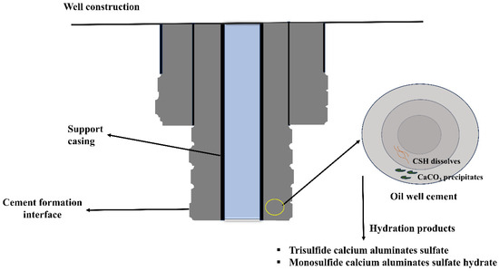
Figure 1.
Oil well cementing.
During the early 2000s, the phenomenon of gas movement and leakage through the cemented annulus was brought to attention [6,7]. Ongoing research endeavors are being conducted to explore potential techniques aimed at the prevention and management of gas migration [8]. The utilization of cement mixture is widely prevalent in the oil and gas sector owing to its inherent characteristics such as static gel strength, as well as its ability to hydrate and solidify [9]. The calculation of the transition time involves the utilization of static gel strength. The duration necessary for the slurry to undergo a transition from a liquid state to a solid state is referred to as the solidification time. During this transitional phase, the mixture achieves a gel strength that is capable of accommodating the infusion of gas throughout the cement column [10]. Gas migration, alternatively referred to as gas leakage, is a phenomenon that occurs when gas escapes from its intended containment. One of the primary difficulties encountered in oil and gas wells has been identified as a significant difficulty [11,12]. Gas migration is responsible for approximately 30% of cement failures in well construction, according to estimates. Recent and comprehensive research endeavors focused on evaluating the occurrence of barrier and stability failures in offshore and onshore wells of different ages have revealed a wide range of rates, spanning from 2% to 70%. Notably, a failure rate of 20% has been documented specifically for gas leaking incidents [13].
The highest level of approximation encompasses all aspects of well integrity, including the movement of gas with cement operations, but no specific data has been provided. The well’s longevity is improved with the implementation of cement casing, which facilitates zonal seclusion [14]. Achieving comprehensive zonal isolation is of utmost importance and indispensable for ensuring operational success, particularly in wells characterized by elevated temperatures and pressures. The laboratory-based design of cement slurries takes into account the downhole conditions, which are typically replicated by simulation in the laboratory setting. The designs frequently fail to accurately replicate downhole circumstances due to their reliance on idealized conditions [15]. In the year 2010, a blowout incident occurred in Mexico due to substandard cement quality [16]. Consequently, the geoenergy sector has acknowledged the necessity of implementing a quantitative approach for monitoring the performance of well cementing. The integrity of cementing can be compromised by various mechanisms, including debonding, radial cracking, and plastic deformation of the cement. The application of high-pressure, high-temperature conditions leads to thermal fluctuations and cycling, which cause the cement sheath to undergo expansions and contractions [17]. The repetitive and cyclical motion described has an impact on the structural soundness of both unset and set cement, resulting in the development of cracks [18]. Over time, these fissures facilitate the movement of gas. One potential approach to address slurries exposed to elevated temperature and pressure involves incorporating cement with a reduced elastic modulus, less shrinkage, decreased yield point, and enhanced tensile strength. Therefore, to attain the desired qualities, a range of polymers, latexes, additives, and resins is used in cement slurries [18,19,20].
Due to its versatile characteristics, latexes are widely used as adhesion promoters. According to the cited source, the utilization of flexible cement designs has the potential to effectively mitigate the occurrence of cracks. The enhancement of the anti-channeling power of cement slurry, the improvement in the bonding between cement and casing, and the reduction in permeability have been observed [21]. Styrene butadiene polymer (SBR) is extensively employed in the process of oil well cementing because of its exceptional mechanical characteristics, capacity to diminish cement shrinkage, and ability to minimize fluid loss through the coalescence of SBR particles [17,22]. To enhance the adhesive characteristics of SBR, carboxylate functional groups in latex emulsions are reacted with a highly acidic monomer [23]. There has been a recent surge in interest in the incorporation of functional polymer additives into cement, as evidenced by several studies [24,25,26]. Bauregger et al. [27] conducted a study on cement hydration, wherein they observed that the presence of styrene–butadiene inhibits the processes comprising silicate and aluminate compounds.
The addition of SBR latex to cement paste resulted in a reduction in the amount of mixing water required, and the effectiveness of water reduction increased with higher levels of latex incorporation. The research conducted by Barluenga and Hernández [28] also demonstrated that the mobility of mortar increased as the content of SBR latex aggregates increased. The determination of polymer-treated cement qualities also relies on the consideration of workability. The workability of ball-bearing operation can be influenced by factors such as entrained air and the utilization of resins [29]. A mathematical slump equation is proposed for SBR-treated cement mortar, considering the quantity of polymer and its dilution qualities. Tran et al. [30] have observed that the functioning of ball bearings has an impact on the fluidity of cement grains, leading to flow restrictions.
As stated by Barluenga and Hernández [28], the inclusion of hydrophilic compounds derived from SBR in concrete has been found to enhance its workability and promote the entrapment of air, hence reducing the movement of cement particles. The determination of the mechanism by which SBR latex enhances fluidity and the need for further investigation on cement treated with polymers are both important aspects to consider. SBR latex, which is recognized for its inherent hydrophobic properties, introduces the formation of bubbles within the mixture [31]. Furthermore, the carboxylate groups of styrene–butadiene particles can form chelates with calcium ions that are found in the pore solution [32]. Numerous scholars have conducted investigations on the impact of polymer incorporation into cement, examining various aspects such as mechanical characteristics and hydration through the utilization of standardized testing methods [33,34,35]. The major factor chosen for identifying changes in polymer-treated cement is electrical resistivity. The attribute in question is unaffected by the size of the sample and offers valuable insights about the behavior of the material across various phases of the curing process. This research examines the behavior of XSBR cement slurry at different phases of curing through the utilization of electrical resistivity. The findings of this study have the potential to be applied in areas such as soil grouting and the sealing of leaky oil and gas wells.
Study Objective
Although numerous studies have been undertaken to investigate the impact of SBR on the characteristics of cement, most of these investigations have been conducted in a laboratory on strength development aspects [36,37,38,39,40]. Moreover, few studies adopted the electromechanical impedance technique [41], carbon nanotubes [42], and piezo sensors [43] for monitoring the material behavior, particularly in superstructures. Studies on monitoring underground projects such as well cementing with electrical-based methods are very limited [44].
This research discusses the incorporation of XSBR content into cement and examines the resulting alterations in material behavior through the utilization of electrical resistivity measurements. The quantification of the chemical interaction between polymer and cement slurry is achieved through the measurement of electrical resistivity over a 24 h curing period. The fluid loss data pertaining to cement and polymer-modified cement were both recorded and afterwards subjected to modeling. The experimentation aims to determine the influence of XSBR on both compressive strength and electrical resistivity. The investigation and modeling of the impact of polymer addition on the compressive strength of Class H cement were ultimately conducted and modeled. In addition to being easy to use, the electrical resistivity method provides a basic understanding of the related structural mechanism, leading to increased stiffness due to hydration. The suggested tool can be used for many additional purposes besides strength monitoring. This method is simple to use in the construction sector to monitor well-cement projects.
2. Experimental Investigation
2.1. Materials and Sample Preparation
To prepare cement slurry, Class H cement was used in this study with a water-to-cement (w/c) ratio of 0.38. The samples were prepared according to the API RP 10B-2 standards [36]. XSBR polymer is added as an additive of varying percentages (1%, 3%, and 5%), and density measurements of the samples are made after 35 s of mixing. The sample was conditioned for 30 min before placing the slurry in the HPHT cell for testing. Initial resistivity measurements were performed using a conductivity probe, which measured the conductivity of the slurry immediately after mixing, and then the value obtained was converted to resistivity. The resistance of the cement slurry throughout the test was measured using an inductance–capacitance–resistance (LCR) device at different frequencies. Eight samples of polymer-treated cement slurries were prepared and tested for up to one day and 28 days of curing. Cement, water, and XSBR were mixed at a speed of 4000 rpm for 15 s and then 35 s at a speed of 12,000 rpm. Cylindrical specimens of 2 inches in diameter and 4 inches in height were prepared using plastic molds for compression and setting time testing. For real-time monitoring of cement samples, two wires were inserted into cement specimens through which the necessary readings were taken [45].
2.2. Electrical Resistivity
A digital resistivity meter measuring electrical resistivity within a range varying from 0.01 Ω-m to 400 Ω-m was used in this study. The calibration of the meter was performed using a standard sodium chloride solution. An LCR meter was used to measure the effect of curing and its impact on compressive strength of cement. The two-wire method was used to measure the resistance at a frequency of 300 kHz to reduce the contact resistance. The electrical resistance is correlated with resistivity with the following Equation (1):
where D is the distance between wires, A is the cross-sectional area through which current flows, and (D/A) is the nominal geometry factor. Cement is generally known to be an insulator, which does not allow current to pass through it. Hence it is difficult to measure the current flow in cement. To overcome this, (D/A) in Equation (1) was replaced by an experimentally determined effective calibration factor (K) by measuring the bulk resistance (R) and the resistivity (ρ) of the material at the same time [37]. The factors that are responsible for changes in resistivity include curing, stress, additives, and pressure loading, etc. The change in resistivity is shown in the below Equation (2).
2.3. Electrical Impedance
The electrical impedance of cement and treated cement was measured in order to examine their electrical characteristics. The impedance properties of the treated cement were evaluated through the utilization of alternating current (AC) measurements. The findings provide insights into the disparities in electrical impedance observed between cement samples that have undergone treatment and those that have not. Impedance spectroscopy was measured using the two-probe technique with AC [46,47]. For AC measurements over a wide range of frequencies, an LCR meter (E4980A, Keysight Technologies, Santa Rosa, CA, USA) with 0.01U precision was employed. This LCR meter is capable of both low and high ranges of impedance. Panda et al. [48] provided insight into the equivalent electrical circuit of the composite material behavior (see Figure 2). If the material’s bulk capacitance (Cb) is ignored, the overall impedance of the corresponding circuit is calculated using Equation (3).
where Z denotes the impedance, Rb is the cement (bulk) resistance, Rc denotes the contact resistance to electricity, denotes the angular frequency of the AC signal used for the tests, and Cc denotes the contact inductance.
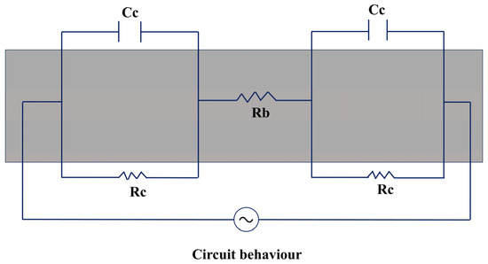
Figure 2.
Equivalent circuit of the impedance equation.
2.4. Fluid Loss Testing
The fluid loss test was conducted using a high-pressure, high-temperature apparatus constructed from steel. Furthermore, the apparatus is equipped with grooves to facilitate the measurement of electrical resistivity. The resistance during the 30 min fluid loss test was measured by the modified cell. The measuring cell possesses a diameter of 5 cm, accompanied with a maximum volume of 500 cm3. The LCR was employed for the purpose of quantifying the vertical resistance shown by cement slurry in the context of fluid loss testing. The alteration in resistance was then associated with variations in resistivity. High-purity experimental-grade nitrogen gas was used as it is relatively inert and does not have harmful health effects. Moreover, the application of nitrogen gas is advantageous due to its non-reactivity with cement. The alteration in resistivity was noticed through the act of opening the output valve. The application of gas pressure leads to fluid depletion, resulting in the construction of a cohesive network of pores, which subsequently leads to the occurrence of gas leakage. This phenomenon replicates the characteristics exhibited by gas leaks in a downhole environment. The pressure applied following the blow-out event was consistently maintained at a fixed value of 100 pounds per square inch (psi) for a duration of 30 min. For the fluid loss test of all specimens, different cement slurries of 315 cm3 in volume were prepared and poured into the cell as shown in Figure 3. The purpose of fluid test is to arrive at the resilience of cement slurry to applied pressures.
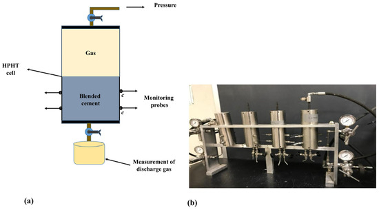
Figure 3.
(a) Mechanism of HPHT test, (b) lab setup.
Initially, the cement slurry was prepared and then placed into the HPHT device. A fluid loss test was subsequently conducted by applying gas pressure at 100 psi. During the test, the fluid loss was collected in a bottom beaker. The collected data was used to model fluid loss behavior using both the API static fluid loss model and the hyperbolic model, which are further discussed in Section 2.5. Simultaneously, the electrical resistance of the cement slurry was measured throughout the fluid loss test. The absolute values of both fluid loss and corresponding resistivity were plotted to analyze the relationship between the two. After the completion of the test, the sample was taken out of the HPHT device.
2.5. API Static Fluid Loss Model
This model assumes that the filter cake properties are constant with passing time, and the relationship is described below:
where F is volume of fluid loss ), F is initial volume of fluid loss ), t is time (min), and M is model parameter (mL/(min)0.5). From Equation (4), the maximum fluid loss F, when t → ∞ is given by Equation (5):
The API fluid loss model was found to overestimate the total fluid loss of the system if extrapolated beyond the 30 min testing period [49,50].
The relationship between fluid loss with time for cement slurry was investigated in this study. Considering the changes in the cement hydration and cake thickness with time, following relationship was proposed [50]:
where D and E are model parameters.
2.6. Compressive Strength
Cylindrical molds (2 inch diameter and 4 inches in height) were cast and cured for 24 h to 28 days before testing. Hydraulic compression test apparatus was used to quantify the strength of the samples after 1 day of curing with a loading rate of 40 psi/s. The sample was loaded until failure; the compressive behavior of cement was then projected using the model equation as given by Vipulanandan and Maddi [50]. The function of polymer loading is as given below in Equation (7):
where σ = compressive strength, , = compressive strength and corresponding strain, and p, q = material parameters.
3. Results and Discussion
3.1. Electrical Impedance of Polymer-Treated Cement
The electrical impedance of cement and cement treated with XSBR was assessed, and the corresponding results are presented in Figure 4 and Figure 5. To investigate the impact of XSBR content on the electrical properties of cement, AC measurement was employed. The obtained data demonstrate the variations in electrical impedance for cement samples incorporating different amounts of XSBR at two specific curing periods, namely, 24 h and 28 days. The increased polymer content raises the cement medium’s conductivity, lowering the impedance. In contrast, the impedance increases as the polymer percentage drops due to less ionic mobility and fewer conductive routes in the cement treated with the polymer. As the frequency of the polymer-treated cement blends increases, the electrical impedance reduces due to the minimized contact resistance.
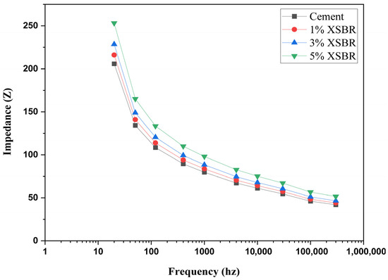
Figure 4.
Electrical impedance of 1-day polymer-treated cement specimens after mixing.
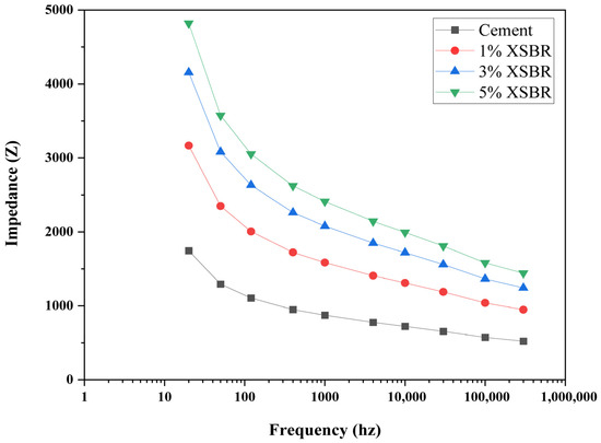
Figure 5.
Electrical impedance of 28-day cured polymer-treated cement specimens.
As seen in Figure 4 and Figure 5, a higher polymer content resulted in a lower electrical impedance, suggesting that the cement slurry had improved ionic conductivity. The hydrophilic and polar properties of XSBR [51] are responsible for this decrease in impedance. They increase the interaction and continuity of the conductive channels, particularly during the early hydration phase, which promotes ion migration in the pore solution. Additionally, samples with 1% XSBR content showed higher impedance values, which could be because of restricted ionic mobility and limited polymer particle dispersion in the cemented cement microstructure. The increased impedance in these formulations is a result of a comparatively greater resistive pore network and a decrease in conductive channels. At the early curing stage (1 day), when hydration is still occurring and the polymer network has not yet completely incorporated into the cement matrix, this trend was more noticeable [52].
Additionally, the impedance values changed with frequency; in all formulations, lower impedance was associated with higher frequencies. Moreover, at higher frequencies, the decreased interfacial polarization and contact resistance are characteristic of dielectric materials. Impedance is decreased at high frequencies because the capacitive action predominates, and ions are insensitive to slower polarization effects.
As per the previous literature, it is evident that the selection of additives for cement is primarily based on compressive strength [53,54,55]. In some cases, researchers have conducted durability tests and adjusted the additive quantity depending on the specific requirements and characteristics of the project [56,57,58,59].
3.2. Electrical Resistivity of Polymer-Treated Cement
The electrical resistivity of the polymer-treated cement mixture with and without XSBR was tested using a two-probe approach. Polymer loading reduced the density of polymer-treated cement from 16.4 ppg to 12.4 ppg. Polymer totaling (5%) improves the resistance from 1 Ω.m to 1.23 Ω.m (see Table 1). This shows that electrical resistivity is sensitive to the addition of polymer signifying the chemical interaction between polymer and cement. In contrast to density, which is often assessed solely before any cement testing, resistivity has the potential to be measured from the moment of mixing and even after the cement’s solidification. Figure 6 depicts the trend of polymer-treated cement hydration with polymer addition at one-day curing under atmospheric conditions. The presented trend graphs illustrate the degree of sensitivity of resistivity to variations that occur throughout the process of cement blend curing. Figure 6 provides a summary of the variation in electrical resistivity observed using a two-probe method over the curing period of modified cement polymer treated with XSBR.

Table 1.
The 24 h resistivity monitoring of polymer-treated cement.
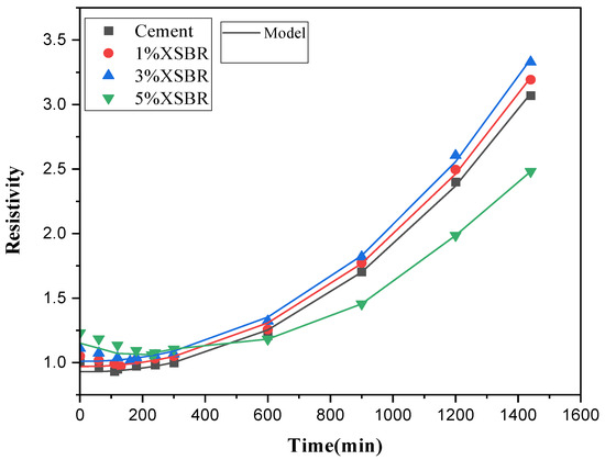
Figure 6.
Resistivity variations with different contents of polymer at one day.
Timely variations with and without XSBR content were found in a similar way (see Figure 7). The resistivity is found to be increasing with time after mixing. The polymer sticking to the exterior face of the cement particles caused a rise in electrical resistance shortly after mixing. It keeps water and cement particles from coming into contact. The resistance of the polymer-treated material increased considerably as it hardened due to the development of solid hydration products and the XSBR layer blocking the conduction channel. Sun et al. [31] reported that ions can freely travel through the cement matrix, facilitating electrical conductivity. Ion movement is hampered as the number of pores decreases. The limited flow of ions within the cement matrix lowers total electrical conductivity and raises electrical resistance.
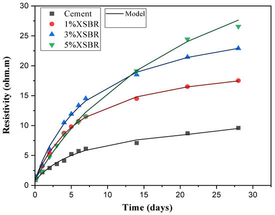
Figure 7.
Resistivity variations with different contents of polymer at 28 days.
3.3. Fluid Loss Monitoring
Polymer is added to the cement mixture to prevent fluid loss, and it also supports the matrix in other ways too. When added to cement, XSBR minimizes fluid loss. Fluid loss for polymer-treated cement without and with XSBR was 118.6 mL, 98.3 mL, 76.8 mL, and 59.2 mL, respectively, for additions of 0%, 1%, 3%, and 5% XSBR (see Table 2). From Figure 8, it was found that addition of XSBR reduced the fluid loss for polymer-treated cement, which decreased by 17%, 33%, and 48% by addition of 1%, 3%, and 5% XSBR content. Reduction in fluid loss indicates that the styrene–butadiene polymer fills the pores of the cement slurry. Additionally, the fluid loss of the samples was modeled using an API model.

Table 2.
API fluid loss model parameters for polymer-treated cement.
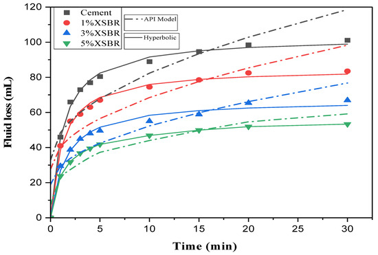
Figure 8.
The 30 min fluid loss test for polymer-treated cement.
3.4. Critical Fluid Loss
The term “critical fluid” refers to the complete loss of fluid that occurs just prior to the detection of a gas leak. The experiments conducted to determine the critical fluid loss values for different polymer additions (0%, 1%, 3%, and 5%) yielded results of 46 mL, 41 mL, 38 mL, and 32 mL, respectively. These values correspond to a total fluid loss of 101 mL, 83 mL, 67 mL, and 53 mL, as depicted in Figure 9. The trend observed in the ratio of the critical fluid loss to the total fluid loss indicated an increase with increasing polymer loading. Specifically, the values for this ratio were found to be 0.45, 0.49, 0.56, and eventually reaching 0.60 at a polymer loading of 5%. The observed upward trend in the percentage values indicates the impact of polymer materials in enhancing resistance to gas leakage.
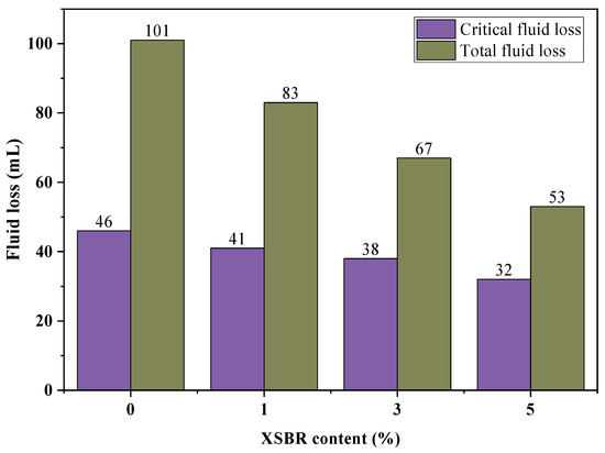
Figure 9.
Total and critical fluid loss values for polymer-treated cement.
Upon treatment with XSBR, the cement underwent a process wherein a polymeric connection was established among the particles at their various surfaces. This connection gradually expanded as the cement underwent hydration. Moreover, this was because, when the smaller percentage of XSBR was applied, the cement matrix’s particles expanded unevenly in different directions, increasing the distance between them. Furthermore, the degree of polymerization increased due to the dehydration of CSH within the cement matrix, further decreasing the degree of integration between the hydration products. The cohesiveness and internal friction angle significantly decreased due to these elements being taken together. At the macro-scale, this reduction led to more intricate tensile failures. This behavior has been observed in earlier research [60,61]. The application of cement polymer treatment to XSBR resulted in the development of a robust adhesive strength that exhibits resistance to water displacement. The presence of the polymeric link impeded the flow of water and filled the holes inside the specimens containing a polymer matrix, resulting in the formation of a pliable film that is impermeable. Additionally, the decrease in pore size inside the polymer blends results in a corresponding decrease in fluid loss, which is directly proportional to the polymer concentration. This observation aligns with the findings reported by Vipulanandan and Mohammed [37] as well as Tan et al. [62] in their respective studies.
3.5. Fluid Loss and Resistivity Correlation
The change in fluid loss was correlated with the resistivity change in the modified HPHT cell. Figure 10 shows that, with increasing polymer loading, the change in resistivity decreases. The lowest change in resistivity observed during testing was for 5% polymer-treated cement with final resistivity after 30 min of testing equal to about 5 Ω.m (less than half of the final resistivity for polymer-treated cement).
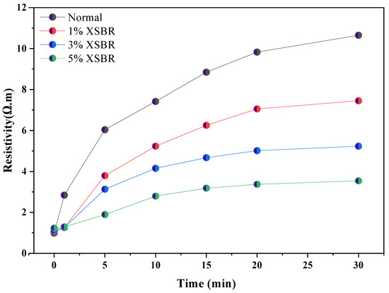
Figure 10.
Change in resistivity with fluid loss for XSBR-treated cement.
3.6. Compressive Behavior of Polymer-Treated Cement
Compressive strength of cement is assessed in this study to understand the strength gain. Cement’s compression increased with polymer loading after 1 day of curing to 10.46 MPa as seen from Table 3.

Table 3.
Compressive behavior parameters for polymer-treated cement.
Figure 11 depicts the stress–strain behavior of cement and polymer-treated cement after one-day curing. The stress–strain data demonstrates that the stress level increases with an increase in polymer content while maintaining a constant proportion of strain. The presence of denser phases becomes more pronounced in the blends as the polymer concentration of the treated cement is elevated, resulting in the development of increased hardness in the blends. Consequently, the specimens experience an increase in the vertical compressive force for a given percentage strain. Consequently, the magnitude of stress at its maximum value increases proportionally with the concentration of polymer. As an illustration, the maximum stress seen after a curing period of one day was recorded as 10.33 MPa, 11.52 MPa, 12.02 MPa, and 14.23 MPa for polymer compositions consisting of 0%, 1%, 3%, and 5%, correspondingly.
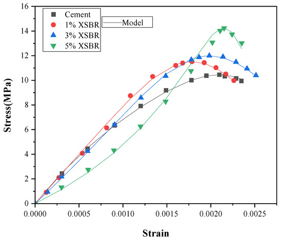
Figure 11.
Compressive stress–strain curves for 1-day cured polymer-treated cement specimen.
As the duration of the curing period is extended, there is an increase in the occurrence of cementations within the mixtures, leading to the formation of cementitious products with enhanced strength. This principle is applicable to all polymer constituents. In addition, the application of hydration XSBR polymer to cement has the potential to effectively seal macropores. The effect of plugging macropores resulted in a decrease in the penetrability of the final cement paste. In addition, it is worth noting that the CSH gel formed during the process of cement hydration exhibited porosity. Moreover, the observation of a smaller pore size in the gel indicated a decrease in the quantity of fractals as the duration of curing progressed. The stress–strain outcomes depicted in Figure 12 provide evidence for this assertion. As an illustration, the peak compressive stress values for curing times of one day and 28 days were found to be 12.02 MPa and 31.89 MPa, respectively, when the polymer proportion in the blend was 3%.
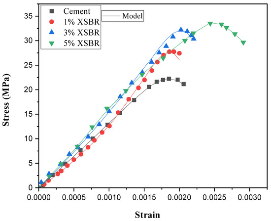
Figure 12.
Compressive stress–strain curves for 28-day cured polymer-treated cement specimen.
Cement paste’s microstructure is closely related to its mechanical properties [63]. The crystalline structure of traditional cement paste is characterized by a high proportion of amorphous solids, which include a mixture of needle, rod, and lamellar-shaped crystals, as well as many micropores and microcracks [64,65]. This mixture leads to increased porosity and decreased toughness. On the other hand, polymer-modified paste offers a more advantageous situation, displaying a microstructure with fewer pores and a thick, homogenous nature due to the efficient filling that polymer particles give. The XSBR particles and film are essential in covering the hydration products’ surface and efficiently packing the pores and fissures in the modified cement system [66]. The freshly created inorganic mineral phases and the polymer particles also have a bonding effect. In the presence of stress, the polymer film first absorbs the stress before dispersing it, affecting the hydrated crystal’s structure. This process effectively withholds certain mechanical forces, increasing cement-based composite toughness. The denser phases produced by the XSBR and cement blend are validated by the trends that have been observed, which include a decrease in the resistivity index and fluid loss, along with an improvement in compressive strength. This simple approach can be easily extended, especially with new 2D materials, notably those belonging to the polymer family, which offer a chance for their application in the building sector as grout materials with various chemical and physical characteristics.
3.7. Micro-Structural Analysis
Scanning electron microscopy (SEM), which examines the microstructural alterations in cement treated with XSBR, supported the findings. The SEM data are shown in Figure 13, which clearly illustrates the mixtures’ shape. Figure 13a shows that the pure cement sample, after hydration, has a more open microstructure and no thick filler material. Furthermore, the cement paste exhibits noticeable microcracks, some more comprehensive than 1–3 μm, which may be a factor in the material’s reduced strength.
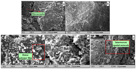
Figure 13.
SEM micrographs of (a) cement, (b) cement—2% XSBR, (c) cement—1% XSBR, (d) cement—2% XSBR, and (e) cement—3% XSBR.
Conversely, samples containing XSBR latex exhibit a much denser microstructure, full of many crystalline particles with irregular shapes packed into tiny gaps. When 3% XSBR latex is added, a noticeable polymer film coating is applied to the cement grains (Figure 13d,e), minimizing and bridging the gaps and cracks. As a result of this addition, there are significantly fewer and smaller microcracks, which enhance structural continuity and narrows crack widths to prevent further expansion. The fluid transverse relaxation time and specimen pore size are closely connected; longer periods are associated with larger pores. This is based on the cement slurries’ pore size variations and associated relaxation times, as documented in earlier research [67]. The amount of XSBR latex injected directly correlates with this densification and enhanced microstructural integrity. Adding 3% XSBR latex to cement significantly improves its electrical resistivity and fluid retention, indicating that XSBR helps improve the microstructural characteristics of cement.
Strength results on Class H cement blended with XSBR revealed significant microstructural modifications and enhanced mechanical performance. Hydration over extended curing periods increased cementitious product formation, enhancing strength. Compressive stress rose from 12.02 MPa (1 day) to 31.89 MPa (28 days) at 3% XSBR, corroborating microstructure refinement. Porosity analysis indicated smaller pore sizes and reduced fractals over time, aligning with decreased permeability. SEM imaging exhibited the formation of continuous XSBR film coating cement particles, with visible polymer strands interwoven within the CSH matrix. Carboxyl (–COOH) groups react with Ca(OH)2 to form calcium carboxylate, strengthening bonding and reducing free Ca(OH)2 [68]. Simultaneously, –COOH chelates Ca2+/Al3+ ions and hydrogen-bonds with CSH gel [69], refining the phases and delaying ettringite stiffening (see Figure 14). These exhibit XSBR’s dual role in improving electrical properties, fluid loss control, and mechanical strength in oil well cementing applications.
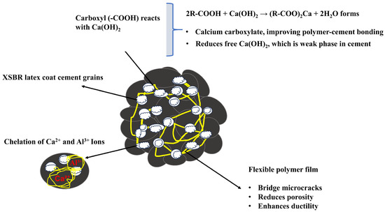
Figure 14.
XSBR film formation on cement particles.
4. Conclusions
Based on the results obtained from this study, the subsequent conclusions were derived and are elaborated upon in the subsequent discussion.
The compressive strength of cement treated with polymers exhibited a notable increase as the polymer content was increased, regardless of the specific curing conditions. The addition of 5% XSBR to cement resulted in a 27% improvement in compressive strength as the SBR concentration climbed from 0% to 5% during a 24 h curing period.
The monitoring of resistivity changes in polymer-treated cement during a 30 min fluid loss test demonstrated the sensitivity of polymer-treated cement to fluctuations in additives and moisture levels.
The electrical resistivity of the cement treated with XSBR exhibited a notable decrease as the XSBR concentration was increased. The observed phenomenon can be attributed to the formation of dense hydration products and the presence of the XSBR layer, which effectively impedes conduction.
The impedance of the cement treated with XSBR exhibited enhancement as the XSBR concentration was increased. The electrical impedance characteristics of polymer-treated cement offer a more comprehensive foundation for analyzing cement processes, contributing to an enhanced understanding of polymer-treated cement.
Future studies should focus on expanding the practical usefulness and knowledge of cement composites modified with XSBR. It is advised to use methods like Fourier-Transform Infrared Spectroscopy (FTIR) and X-ray Diffraction (XRD) to confirm the chemical interactions between XSBR and cement hydration products. Furthermore, even though BET and MIP were used to study the pore structure, more research should concentrate on developing quantitative relationships between the distribution of pores and important performance metrics, such as electrical resistivity and fluid loss. In-depth microstructural and interfacial transition zone (ITZ) analysis is also necessary to examine the possible adverse consequences of high polymer doses (e.g., 5% or more), such as interfacial weakening or decreased matrix integrity. Future research should incorporate HPHT curing environments and carry out long-term durability experiments in order to replicate field-relevant circumstances.
Author Contributions
Conceptualization, methodology, investigation, validation, formal analysis, resources, writing—original draft preparation, G.P.P.; conceptualization, methodology, investigation, validation, formal analysis, writing—original draft preparation, T.V.N.; methodology, investigation, validation, formal analysis, writing—original draft preparation, G.S.B.; methodology, investigation, validation, formal analysis, writing—original draft preparation, S.L.G. All authors have read and agreed to the published version of the manuscript.
Funding
This research received no external funding.
Data Availability Statement
Data is contained within the article or supplementary material.
Conflicts of Interest
The authors declare no conflicts of interest.
References
- Elmgerbi, A.; Askar, I.A.; Fine, A.; Thonhauser, G.; Ashena, R. Cellulose nanocrystals (CNCs) as a potential additive for improving API class G cement performance: An experimental study. Nat. Gas Ind. B 2023, 10, 233–244. [Google Scholar] [CrossRef]
- Ibukun, M.; Elyan, E.; Amish, M.; Njuguna, J.; Oluyemi, G.F. A Review of Well Life Cycle Integrity Challenges in the Oil and Gas Industry and Its Implications for Sustained Casing Pressure (SCP). Energies 2024, 17, 5562. [Google Scholar] [CrossRef]
- Bihua, X.; Bin, Y.; Yongqing, W. Anti-corrosion cement for sour gas (H2S-CO2) storage and production of HTHP deep wells. Appl. Geochem. 2018, 96, 155–163. [Google Scholar] [CrossRef]
- Bai, R.; Zhang, J.; Yan, C.; Liu, S.; Wang, X.; Yang, Z. Calcium hydroxide content and hydration degree of cement in cementitious composites containing calcium silicate slag. Chemosphere 2021, 280, 130918. [Google Scholar] [CrossRef]
- Bao, H.; Xu, G.; Wang, Q.; Peng, Y.; Liu, J. Study on the deterioration mechanism of cement-based materials in acid water containing aggressive carbon dioxide. Constr. Build. Mater. 2020, 243, 118233. [Google Scholar] [CrossRef]
- Trudel, E.; Bizhani, M.; Zare, M.; Frigaard, I. Plug and abandonment practices and trends: A British Columbia perspective. J. Pet. Sci. Eng. 2019, 183, 106417. [Google Scholar] [CrossRef]
- Soeder, D.J.; Sharma, S.; Pekney, N.; Hopkinson, L.; Dilmore, R.; Kutchko, B.; Stewart, B.; Carter, K.; Hakala, A.; Capo, R. An approach for assessing engineering risk from shale gas wells in the United States. Int. J. Coal Geol. 2014, 126, 4–19. [Google Scholar] [CrossRef]
- Samdani, G.A.; Rao, S.S.; Gupta, V.P. Gas Migration in PMCD Operations: Influence of Mud Type and Properties. In Proceedings of the IADC/SPE International Drilling Conference and Exhibition, OnePetro, Galveston, TX, USA, 8–10 March 2022. [Google Scholar]
- Kamali, M.; Khalifeh, M.; Saasen, A.; Godøy, R.; Delabroy, L. Alternative setting materials for primary cementing and zonal isolation—Laboratory evaluation of rheological and mechanical properties. J. Pet. Sci. Eng. 2021, 201, 108455. [Google Scholar] [CrossRef]
- Wang, C.; Chen, X.; Wang, R. Do chlorides qualify as accelerators for the cement of deepwater oil wells at low temperature? Constr. Build. Mater. 2017, 133, 482–494. [Google Scholar] [CrossRef]
- Bayanak, M.; Zarinabadi, S.; Shahbazi, K.; Azimi, A. Effects of Nano Silica on oil well cement slurry charactreistics and control of gas channeling. S. Afr. J. Chem. Eng. 2020, 34, 11–25. [Google Scholar] [CrossRef]
- Ahmed, S.; Salehi, S.; Ezeakacha, C. Review of gas migration and wellbore leakage in liner hanger dual barrier system: Challenges and implications for industry. J. Nat. Gas Sci. Eng. 2020, 78, 103284. [Google Scholar] [CrossRef]
- Tao, C.; Rosenbaum, E.; Kutchko, B.G.; Massoudi, M. A brief review of gas migration in oilwell cement slurries. Energies 2021, 14, 2369. [Google Scholar] [CrossRef]
- Jafariesfad, N.; Geiker, M.R.; Gong, Y.; Skalle, P.; Zhang, Z.; He, J. Cement sheath modification using nanomaterials for long-term zonal isolation of oil wells: Review. J. Pet. Sci. Eng. 2017, 156, 662–672. [Google Scholar] [CrossRef]
- Saleh, F.K.; Teodoriu, C. The mechanism of mixing and mixing energy for oil and gas wells cement slurries: A literature review and benchmarking of the findings. J. Nat. Gas Sci. Eng. 2017, 38, 388–401. [Google Scholar] [CrossRef]
- Pranesh, V.; Palanichamy, K.; Saidat, O.; Peter, N. Lack of dynamic leadership skills and human failure contribution analysis to manage risk in deep water horizon oil platform. Saf. Sci. 2017, 92, 85–93. [Google Scholar] [CrossRef]
- Ramalho, R.V.A.; Alves, S.M.; Freitas, J.C.d.O.; Costa, B.L.d.S.; Bezerra, U.T. Evaluation of mechanical properties of cement slurries containing SBR latex subjected to high temperatures. J. Pet. Sci. Eng. 2019, 178, 787–794. [Google Scholar] [CrossRef]
- Peng, Z.; Zeng, W.; Feng, Q.; Zheng, Y. Study on Improving the Toughness of Silicate Cement Stone by Modified Epoxy Resin. Silicon 2022, 15, 3137–3148. [Google Scholar] [CrossRef]
- Assaad, J.J. Development and use of polymer-modified cement for adhesive and repair applications. Constr. Build. Mater. 2018, 163, 139–148. [Google Scholar] [CrossRef]
- Mohamadian, N.; Ramhormozi, M.Z.; Wood, D.A.; Ashena, R. Reinforcement of oil and gas wellbore cements with a methyl methacrylate/carbon-nanotube polymer nanocomposite additive. Cem. Concr. Compos. 2020, 114, 103763. [Google Scholar] [CrossRef]
- Peng, Z.; Lv, F.; Feng, Q.; Zheng, Y. Enhancing the CO2-H2S corrosion resistance of oil well cement with a modified epoxy resin. Constr. Build. Mater. 2022, 326, 126854. [Google Scholar] [CrossRef]
- Vitorino, F.d.C.; Dweck, J.; Ferrara, L.; Filho, R.D.T. Effect of plain and carboxylated styrene-butadiene rubber on the rheological behavior of silica fume-class G Portland cement slurries. J. Mater. Res. Technol. 2020, 9, 5364–5377. [Google Scholar] [CrossRef]
- Zárybnická, L.; Machotová, J.; Mácová, P.; Machová, D.; Viani, A. Design of polymeric binders to improve the properties of magnesium phosphate cement. Constr. Build. Mater. 2021, 290, 123202. [Google Scholar] [CrossRef]
- Schröfl, C.; Erk, K.A.; Siriwatwechakul, W.; Wyrzykowski, M.; Snoeck, D. Recent progress in superabsorbent polymers for concrete. Cem. Concr. Res. 2022, 151, 106648. [Google Scholar] [CrossRef]
- Abd-El-Raoof, F.; Hegazy, A.; Rashwan, M.; Mohamed, W.; Tawfik, A. Dual-functional polymer-modified magnesium oxychloride cement pastes: Physico-mechanical, phase, and microstructure characterizations. J. Build. Eng. 2022, 57, 104898. [Google Scholar] [CrossRef]
- Choi, S.-J.; Bae, S.-H.; Lee, J.-I.; Bang, E.-J.; Ko, H.-M. Strength, carbonation resistance, and chloride-ion penetrability of cement mortars containing catechol-functionalized chitosan polymer. Materials 2021, 14, 6395. [Google Scholar] [CrossRef]
- Baueregger, S.; Perello, M.; Plank, J. Influence of carboxylated styrene–butadiene latex copolymer on Portland cement hydration. Cem. Concr. Compos. 2015, 63, 42–50. [Google Scholar] [CrossRef]
- Barluenga, G.; Hernández-Olivares, F. SBR latex modified mortar rheology and mechanical behaviour. Cem. Concr. Res. 2004, 34, 527–535. [Google Scholar] [CrossRef]
- Ohama, Y. Principle of latex modification and some typical properties of latex-modified mortars and concretes adhesion; binders (materials); bond (paste to aggregate); carbonation; chlorides; curing; diffusion. Mater. J. 1987, 84, 511–518. [Google Scholar]
- Tran, N.P.; Nguyen, T.N.; Ngo, T.D. The role of organic polymer modifiers in cementitious systems towards durable and resilient infrastructures: A systematic review. Constr. Build. Mater. 2022, 360, 129562. [Google Scholar] [CrossRef]
- Sun, K.; Wang, S.; Zeng, L.; Peng, X. Effect of styrene-butadiene rubber latex on the rheological behavior and pore structure of cement paste. Compos. Part B Eng. 2019, 163, 282–289. [Google Scholar] [CrossRef]
- Baueregger, S.; Perello, M.; Plank, J. Impact of carboxylated styrene–butadiene copolymer on the hydration kinetics of OPC and OPC/CAC/AH: The effect of Ca2+ sequestration from pore solution. Cem. Concr. Res. 2015, 73, 184–189. [Google Scholar] [CrossRef]
- Aattache, A.; Mahi, A.; Soltani, R.; Mouli, M.; Benosman, A.S. Experimental study on thermo-mechanical properties of polymer modified mortar. Mater. Des. 2013, 52, 459–469. [Google Scholar] [CrossRef]
- Borhan, T.M.; Al Karawi, R.J. Experimental investigations on polymer modified pervious concrete. Case Stud. Constr. Mater. 2020, 12, e00335. [Google Scholar] [CrossRef]
- Bahranifard, Z.; Tabrizi, F.F.; Vosoughi, A.R. An investigation on the effect of styrene-butyl acrylate copolymer latex to improve the properties of polymer modified concrete. Constr. Build. Mater. 2019, 205, 175–185. [Google Scholar] [CrossRef]
- Vipulanandan, C.; Mohammed, A. Quantify the effect of temperature on the electrical resistivity, yield stress, and HPHT fluid loss of the bentonite-clay drilling mud modified with acrylamide polymer. J. Build. Pathol. Rehabil. 2020, 5, 20. [Google Scholar] [CrossRef]
- Vipulanandan, C.; Mohammed, A. Polymer treated cement rheological and piezoresistive behavior for oil well applications. J. Pet. Sci. Eng. 2015, 135, 50–58. [Google Scholar] [CrossRef]
- Manawadu, A.; Qiao, P.; Wen, H. Characterization of substrate-to-overlay interface bond in concrete repairs: A review. Constr. Build. Mater. 2023, 373, 130828. [Google Scholar] [CrossRef]
- Han, Y.; Cui, B.; Tian, J.; Ding, J.; Ni, F.; Lu, D. Evaluating the effects of styrene-butadiene rubber (SBR) and polyphosphoric acid (PPA) on asphalt adhesion performance. Constr. Build. Mater. 2022, 321, 126028. [Google Scholar] [CrossRef]
- Almajed, A.; Abbas, H.; Almusallam, T.; Al-Salloum, Y. Stabilization of sand using energy efficient materials under normal and extreme hot weathers. J. Clean. Prod. 2021, 285, 124914. [Google Scholar] [CrossRef]
- Xiao, M.; Ju, F.; He, Z.; Ning, P.; Wang, T.; Wang, D. Assessing the Effect of Damage and Steel Fiber Content on the Self-Sensing Ability of Coal Gangue-Cemented Composite by Electrochemical Impedance Spectroscopy (EIS). Materials 2025, 18, 2467. [Google Scholar] [CrossRef] [PubMed]
- Prakash, S.; Bhalla, S.; Zonta, D.; Su, Z.; Glisic, B. Carbon nanotubes doped concrete-based sensor for strain measurements. In Proceedings of the Sensors and Smart Structures Technologies for Civil, Mechanical, and Aerospace Systems, SPIE Smart Structures + Nondestructive Evaluation, Long Beach, CA, USA, 6 March–11 April 2022; Volume 12046, pp. 427–432. [Google Scholar]
- Talakokula, V.; Bhalla, S.; Gupta, A. Monitoring early hydration of reinforced concrete structures using structural parameters identified by piezo sensors via electromechanical impedance technique. Mech. Syst. Signal Process. 2018, 99, 129–141. [Google Scholar] [CrossRef]
- Mammadov, O.; Mahmoud, A.A.; Al-Yaseri, A.; Al Ramadan, M. A Comprehensive Review of Cement Degradation Analysis under Downhole Conditions: CCS/CCUS/CO2-EOR Applications. ACS Omega 2025, 10, 28515–28533. [Google Scholar] [CrossRef] [PubMed]
- Vipulanandan, C.; Panda, G.; Maddi, A.R.; Wong, G.; Aldughather, A. Characterizing Polymer treated Cement Modified with Styrene Butadiene Polymer for Quality Control, Curing and to Control and Detect Fluid Loss and Gas Leaks Using Vipulanandan Models. In Proceedings of the Offshore Technology Conference, OTC, Houston, TX, USA, 6–9 May 2019; p. D021S021R006. [Google Scholar]
- Vipulanandan, C.; Aldughather, A.; Panda, G.; Wong, G. Real-Time Gas Leak Detection and Quantification using Smart Cement. In Proceedings of the International Petroleum Technology Conference, Dhahran, Saudi Arabia, 13–15 January 2020. [Google Scholar]
- Vipulanandan, C.; Prashanth, P. Impedance spectroscopy characterization of a piezoresistive structural polymer composite bulk sensor. J. Test. Eval. 2013, 41, 898–904. [Google Scholar] [CrossRef]
- Panda, G.P.; Bahrami, A.; Nagaraju, T.V.; Isleem, H.F. Response of High Swelling Montmorillonite Clays with Aqueous Polymer. Minerals 2023, 13, 933. [Google Scholar] [CrossRef]
- Panda, G.P. Real-Time Monitoring and Characterization of Smart Cement and Soil with Polymer Modification to Control Gas Leakage and Corrosion. Ph.D. Thesis, University of Houston, Houston, TX, USA, 2020. [Google Scholar]
- Vipulanandan, C.; Maddi, A.R. Characterizing the thermal, piezoresistive, rheology and fluid loss of polymer treated foam cement slurries using artificial neural network and Vipulanandan Models. J. Pet. Sci. Eng. 2021, 207, 109161. [Google Scholar] [CrossRef]
- Lamlong, C.; Taweepreda, W. Coating of porous PVC-PEG memebrane with crosslinkable XSBR for O2/N2 and CO2/N2 separation. Polymer 2016, 96, 205–212. [Google Scholar] [CrossRef]
- Liu, Q.; Lu, Z.; Hu, X.; Chen, B.; Li, Z.; Liang, R.; Sun, G. A mechanical strong polymer-cement composite fabricated by in situ polymerization within the cement matrix. J. Build. Eng. 2021, 42, 103048. [Google Scholar] [CrossRef]
- Panda, G.; Vipulanandan, C. Detection and quantification of Gas Leak in Smart Cement. In Proceedings of the Center for Innovative Grouting Material and Technology, CIGMAT-2019 Conference & Exhibition, Houston, TX, USA, 1 March 2019; pp. 1–2. [Google Scholar]
- Baghini, M.S.; Ismail, A.; Karim, M.R.; Shokri, F.; Firoozi, A.A. Effect of styrene–butadiene copolymer latex on properties and durability of road base stabilized with Portland cement additive. Constr. Build. Mater. 2014, 68, 740–749. [Google Scholar] [CrossRef]
- Baghini, M.S.; Ismail, A.; Pour Asghar, M.; Fendereski, G.; Sadeghi, M. Measuring the effects of styrene butadiene copolymer latex-Portland cement additives on properties of stabilized soil-aggregate base. Int. J. Pavement Res. Technol. 2018, 11, 458–469. [Google Scholar] [CrossRef]
- Nitnara, P.; Pongmuksuwan, P.; Kitisatorn, W. Development of polymer binder for properties enhancement of soil cement. Mater. Today Proc. 2022, 57, 975–979. [Google Scholar] [CrossRef]
- Wang, W.; Cheng, Y.; Chen, H.; Tan, G. Polymeric Composites in Road and Bridge Engineering: Characterization, Production and Application. Polymers 2023, 15, 874. [Google Scholar] [CrossRef]
- Kok, B.V.; Yilmaz, M. The effects of using lime and styrene–butadiene–styrene on moisture sensitivity resistance of hot mix asphalt. Constr. Build. Mater. 2009, 23, 1999–2006. [Google Scholar] [CrossRef]
- Esaker, M.; Hamza, O.; Elliott, D. Monitoring the bio-self-healing performance of cement mortar incubated within soil and water using electrical resistivity. Constr. Build. Mater. 2023, 393, 132109. [Google Scholar] [CrossRef]
- Yang, H.; Wang, L.; Huang, G.; Zhao, J.; Yang, C.; Bi, Z.; Guo, Y.; Liu, W.V. Effects of compressive cyclic loading on the fatigue properties of oil-well cement slurries serving in deep downhole environments. Constr. Build. Mater. 2024, 428, 136360. [Google Scholar] [CrossRef]
- Zhang, Z.; Yuan, Z.; Ye, S.; Li, Y.; Yang, L.; Pang, X.; Lv, K.; Sun, J. The influence of cyclic loading on the mechanical properties of well cement. Energies 2024, 17, 3856. [Google Scholar] [CrossRef]
- Tan, E.H.; Zahran, E.M.; Tan, S.J. A comparative experimental investigation into the chemical stabilisation of sandstone aggregates using cement and styrene-butadiene copolymer latex for road sub-base construction. Transp. Geotech. 2022, 37, 100864. [Google Scholar] [CrossRef]
- Yuan, Q.; Xie, Z.; Yao, H.; Huang, T.; Fan, M. Hydration, mechanical properties, and microstructural characteristics of cement pastes with different ionic polyacrylamides: A comparative study. J. Build. Eng. 2022, 56, 104763. [Google Scholar] [CrossRef]
- Zajac, M.; Skibsted, J.; Skocek, J.; Durdzinski, P.; Bullerjahn, F.; Ben Haha, M. Phase assemblage and microstructure of cement paste subjected to enforced, wet carbonation. Cem. Concr. Res. 2020, 130, 105990. [Google Scholar] [CrossRef]
- Zhang, H.; Xu, Y.; Gan, Y.; Chang, Z.; Schlangen, E.; Šavija, B. Microstructure informed micromechanical modelling of hydrated cement paste: Techniques and challenges. Constr. Build. Mater. 2020, 251, 118983. [Google Scholar] [CrossRef]
- Zhao, J.; Hu, M.; Liu, W.; Feng, J.; Zhang, H.; Liu, M.; Guo, J. Toughening effects of well-dispersed carboxylated styrene-butadiene latex powders on the properties of oil well cement. Constr. Build. Mater. 2022, 340, 127768. [Google Scholar] [CrossRef]
- Yang, H.; Wang, L.; Yang, C.; Zhao, J.; Huang, G.; Guo, Y.; Liu, W.V. Mechanical performance of oil-well cement slurries cured and tested under high-temperatures and high-pressures for deep-well applications. Cem. Concr. Res. 2023, 175, 107355. [Google Scholar] [CrossRef]
- Madeja, B.; Gebauer, D.; Marsiske, M.R.; Ott, A.; Rückel, M.; Rosenberg, R.; Baken, A.; Stawski, T.M.; Fernandez-Martinez, A.; Van Driessche, A.E.; et al. New insights into the nucleation of portlandite and the effects of polymeric additives. Cem. Concr. Res. 2023, 173, 107258. [Google Scholar] [CrossRef]
- Gao, C.; Zeng, H.; Xu, J.; Xu, D.; Ma, Y.; She, W.; Hu, Z.; Tang, J.; Liu, J. Collaborative enhancement in “strength-toughness-elastic modulus” of calcium-silicate-hydrate (CSH) based organic-inorganic composites: Chemical bonding and cracking path optimization. Cem. Concr. Res. 2024, 187, 107709. [Google Scholar] [CrossRef]
Disclaimer/Publisher’s Note: The statements, opinions and data contained in all publications are solely those of the individual author(s) and contributor(s) and not of MDPI and/or the editor(s). MDPI and/or the editor(s) disclaim responsibility for any injury to people or property resulting from any ideas, methods, instructions or products referred to in the content. |
© 2025 by the authors. Licensee MDPI, Basel, Switzerland. This article is an open access article distributed under the terms and conditions of the Creative Commons Attribution (CC BY) license (https://creativecommons.org/licenses/by/4.0/).