Article

Terephthalic-co-glycerol-g-fumaric Acid: A Promising Nanopolymer for Enhancing PPSU Membrane Properties

1
Department of Civil Engineering, University of Technology-Iraq, Alsinaa Street 52, Baghdad 10066, Iraq
2
Membrane Technology Research Unit, Department of Chemical Engineering, University of Technology-Iraq, Alsinaa Street 52, Baghdad 10066, Iraq
3
Department of Mechanical & Aerospace Engineering, Monash University-Clayton Campus, Melbourne, VIC 3800, Australia
4
Department of Chemical & Biological Engineering, Monash University-Clayton Campus, Melbourne, VIC 3800, Australia
5
Division of Process Engineering, College of Science and Technology, Chadli Bendjedid University, El-Tarf 36000, Algeria
6
NYUAD Water Research Centre, New York University, Abu Dhabi Campus, Abu Dhabi P.O. Box 129188, United Arab Emirates
7
Institute of Membrane Technology, National Research Council, (ITM-CNR), Via P. Bucci 17c, 87030 Rende, Italy
*
Authors to whom correspondence should be addressed.
ChemEngineering 2025, 9(1), 12; https://doi.org/10.3390/chemengineering9010012
Submission received: 9 August 2024 / Revised: 7 January 2025 / Accepted: 14 January 2025 / Published: 21 January 2025

Abstract

:
This study introduces an innovative approach to modifying polyphenylsulfone (PPSU) membranes for wastewater treatment applications. Terephthalic-co-glycerol-g-fumaric acid (TGF) was used as an innovative nanopolymer pore former. By incorporating TGF at varying concentrations, our research investigates its effects on the morphological and surface properties of PPSU membranes. Two different solvents were used to dissolve PPSU, optimizing the properties of the fabricated membranes. The resultant PPSU/TGF membranes were systematically characterized regarding topography, morphological changes, hydrophilicity, chemical composition, and performance against protein and synthetic dyes. Experimental results revealed that adding TGF resulted in a smoother membrane surface. With 6% TGF inclusion in the casting solution, a more porous structure was achieved, as confirmed by SEM analysis, along with significant improvements in porosity and a near doubling of pore size. Although the hydrophilicity of the membranes exhibited only minor enhancement, performance evaluation demonstrated a substantial increase in pure water flux, with an improvement of more than fourfold. Moreover, the retention of BSA and two synthetic dyes was found to be directly proportional to the concentration of the nanopolymer pore former used. These findings highlight the potential advantages of TGF/PPSU membranes for protein separation and synthetic dye separation applications, underscoring their viability for wastewater treatment.

1. Introduction

Synthetic dye-contaminated water streams pose a significant environmental challenge, threatening both human existence and aquatic ecosystems. Uncontrolled contamination, exacerbated by rapid industrialization and population growth, will have dire consequences for future generations [1]. Securing clean water, especially in water-scarce regions, has become increasingly essential. Consequently, extensive research efforts are focused on developing innovative and alternative wastewater treatment and reclamation technologies [2]. Membrane technology stands out as a promising solution, offering a wide range of treatment options that can be optimized for cost-effectiveness [3].
Recent research has explored novel materials that enhance membrane properties, resulting in high-performance membranes. Various physical and chemical approaches, including the use of organic and inorganic materials and nanostructure additives, have been employed to modify membrane surfaces. Despite significant enhancements in specific membrane characteristics, concerns about other features persist [4]. For instance, nanomaterials, while beneficial, may weaken the membrane’s mechanical structure and raise environmental concerns due to potential leaching, ultimately affecting process efficiency and increasing operational and maintenance costs. By contrast, incorporating pore formers into the polymeric matrix presents a viable strategy for improving membrane characteristics. Pore formers, such as polyethylene glycol (PEG), polyvinylpyrrolidone (PVP), poly(terephthalic-co-glycerol-g-fumaric acid), poly(maleic anhydride-co-glycerol) and inorganic salts, act as temporary scaffolds during the phase inversion process, significantly influencing porosity, pore size distribution, and overall morphology. Terephthalic-co-glycerol-g-fumaric acid (TGF) is a polymer of terephthalic acid, glycerol, and fumaric acid. The polymer’s backbone predominantly comprises aromatic terephthalic acid, which gives stiffness and thermal stability, while glycerol adds flexibility and hydrophilicity. Fumaric acid introduces unsaturation and possible crosslinking sites into the polymer matrix, influencing the physical characteristics of the final material. TGF is frequently employed in biomedical devices and filtration membranes due to its remarkable qualities, which include mechanical strength and thermal stability, as well as the inclusion of terephthalic acid in its structure. Furthermore, TGF has good hydrophilicity due to glycerol’s hydroxyl groups, which might be useful in applications that need moisture retention or increased bioactivity. The pore-forming mechanism of TGF includes many essential activities that contribute to its porous structure: (i) Phase separation: during processing, the various segments of TGF (terephthalic acid, glycerol, and fumaric acid) may phase separately, resulting in the development of microdomains within the polymer. (ii) Leaching: soluble components can be removed, commonly performed with a suitable solvent. This phase generates voids and builds the correct pore structure by regulating pore size and distribution. (iii) Thermal treatment: heat processing can further change the morphology of TGF, changing the size and stability of the holes while boosting the overall mechanical characteristics. (iv) Crosslinking: fumaric acid moieties can undergo crosslinking processes to strengthen the porous structure and increase endurance.
By adjusting the type, concentration, and molecular weight of pore formers, manufacturers can tailor membrane structures to meet specific application requirements [5,6,7,8,9,10,11]. This precise control enhances parameters, like permeability, selectivity, mechanical strength, and antifouling properties, broadening the membrane’s applicability across various industries, including water treatment, biomedical engineering, and chemical processing.
The interest in treating highly contaminated water streams containing synthetic dyes has surged across industries, such as cosmetics, paper, textiles, tanning, food, pharmaceuticals, and printing [12,13]. The textile industry, in particular, contributes significantly to dye effluents, discharging substantial amounts into natural water bodies without adequate treatment [14]. Synthetic dyes pose severe health risks, including impaired kidney, liver, brain, and central nervous system functions, and increase the risk of bladder cancer among textile industry workers [15]. Azo dyes, comprising 60–70% of all dyes, are particularly concerning [16]. Hence, addressing wastewater containing dyes is crucial to mitigate these severe environmental and health impacts [17].
The efficiency of synthetic dye separation using membrane-based processes depends heavily on the composition and characteristics of the employed membrane materials. Traditional porous membranes, with their limited porosity, variable pore size distribution, and fouling susceptibility, exhibit reduced selectivity, hindering their effectiveness in high-efficiency applications. Incorporating pore formers is a proposed method to enhance membrane separation efficiency and selectivity.
Polyphenylsulfone (PPSU) is one of the attractive classes of polymeric membranes characterized by their high structural strength and stability, which makes them an ideal choice for water treatment applications, even in challenging conditions. However, PPSU is crippled by their low water permeability due to their dense surface layer. One of the typical practical strategies to overcome this challenge is the application of pore formers. Terephthalic-co-glycerol-g-fumaric acid (TGF) was proposed and tested as a nanopolymer pore-forming agent to modify PPSU. TGF has not been previously tested with this polymer, making this study the first attempt to investigate its potential for creating an efficient membrane capable of removing dyes and proteins, aiming to treat industrial wastewater.
In this study, terephthalic-co-glycerol-g-fumaric acid (TGF) was used as a nanopolymer pore-forming agent to modify polyphenylsulfone (PPSU) membranes, where the TGF content (0, 3, 4, 5, and 6%) within the polymeric matrix was optimized based on the resulting membrane features. Additionally, the effects of two highly aprotic solvents, dimethylacetamide (DMAc) and N-methyl-pyrrolidone (NMP), on membrane formation were investigated. The fabricated membranes were characterized using Fourier transform infrared (FTIR) spectroscopy, contact angle (CA) measurements, field emission scanning electron microscopy (FE-SEM), and atomic force microscopy (AFM) to assess their chemical structure, surface topography, and morphological changes. The membranes’ performance was evaluated against Congo red, Methyl orange, and bovine serum albumin (BSA).

2. Experimental

2.1. Materials

Polyphenylsulfone, Ultrason® (PPSU), with an average molecular weight of 48,000 g/mol and transition temperature Tg = 220 °C, was obtained from BASF, Ludwigshafen, Germany. N, N-Dimethylacetamide (DMAC, >99%) with MW = 87.13 g/mol, and N-methyl-pyrrolidone (NMP, >99.5%) with MW = 99.13 g/mol, terephthalic-co-glycerol-g-fumaric acid (TGF, >98%) with MW = 166.13 g/mol, and bovine serum albumin (BSA) with a molecular weight of 67,000 g/mol were obtained from Avonchem UK. Congo red with MW = 696.6 g/mol and Methyl orange with MW = 327.34 g/mol were purchased from Sigma-Aldrich (St. Louis, MO, USA).

2.2. Preparation of the Membrane

Non-induced phase separation was implemented to fabricate the membranes. Polyphenylsulfone (PPSU) and terephthalic-co-glycerol-g-fumaric acid copolymer nanoparticles (TGFs) were primarily utilized to construct two groups of flat sheet membranes, labelled group M and group S. Group M employed dimethylacetamide (DMAc) as a solvent, whereas group S used N-methyl-pyrrolidone (NMP). The percentage of TGFs in the polymeric matrix was adjusted from 0% to 6%. Table 1 provides the composition of both groups.
Each desired TGF content was dispersed, for one hour, separately in the solvent. After that, the solution was progressively mixed with a magnetic stirrer at room temperature while a set amount of 14% PPSU was added, and the mixing continued until the casting solution became uniform, clear, and yellowish. Air bubbles were eliminated by placing the mixture under a vacuum. Afterwards, utilizing a motorized film applicator (AFA-IV, Changsha, China) China), the resulting polymeric casting solution was cast onto a dry and clean glass substrate while keeping a 200-micron clearance gap. The coagulation was carried out by immersing the cast film immediately into the tap water bath at room temperature.
The prepared membrane was taken out of the bath with care, rinsed several times under a running stream of water, and then placed in distilled water ready for further characterization.

2.3. Characterizations

2.3.1. Membranes Characterization

The chemical structures of the fabricated membrane surfaces were analyzed using Fourier transform infrared (FTIR) spectroscopy. The measurements were performed with a Bruker Tensor 27 FT-IR spectrometer. Initially, a background spectrum was recorded to establish a baseline, followed by the spectra of the membrane samples. All measurements were conducted over the spectral range of 4000 cm−1 to 400 cm−1.
The hydrophilicity of the membranes was assessed using the sessile drop method. An optical contact angle meter (KSV 200 CAM, Jakarta, India) with a measuring range of 4–180° was employed. A 3-microliter droplet of deionized (DI) water was placed on the flat membrane surface, and the angle between the drop and the surface was measured. A higher contact angle indicates lower wettability and vice versa. Measurements were performed at three different locations on each sample, and an average value was recorded to ensure reproducibility.
The microstructure of the fabricated membranes was observed using field emission scanning electron microscopy (FE-SEM) (ZEISS, Jena, Germany). For cross-sectional analysis, membrane samples were fractured in liquid nitrogen. All samples were sputtered with gold before examination to minimize charging effects [18,19].
The surface topography of the membranes was analyzed using an atomic force microscope (AFM) (AFM-SPM AA300, Angstrom Advanced Inc., Stoughton, MA 02072, USA). Three-dimensional images were captured, and data on roughness parameters and mean pore size of the prepared membranes were obtained.
The porosity of the prepared membranes was evaluated using the dry/wet method. Membrane samples with 1 cm × 3 cm dimensions were cut, and their dry weights were recorded. The samples were then immersed in DI water for 24 h at room temperature. After removal, excess water was wiped off with a clean, soft tissue, and the wet weights of the samples were measured. The porosity (ε) of the prepared membranes was calculated using Equation (1) [10]:
ε % = m w m d ρ w A s δ × 100
where mw and md are the wet and dry weight values of the membranes, ρ W is the density of water at 25 °C (0.998 g/cm3), AS is the effective surface area of the membrane (m2), and δ is the membrane thickness (µm). The overall thickness of the membrane was measured using a micrometer screw gauge (Mitutoyo), with the accuracy of the micrometer being 1 µm.
The mean pore size (rm) was calculated based on membrane porosity and pure water flux using the Guerout–Elford–Ferry Equation (2) [10]:
r m = 2.9 1.75 ε 8 η   l   Q ε   A s     Δ P
where ƞ is the water viscosity, Q is the collected volume of the pure water flux per unit time (m3/s), ΔP is the operation pressure, ε is the membrane porosity, and l and As are the thickness and effective surface area of the membrane, respectively.

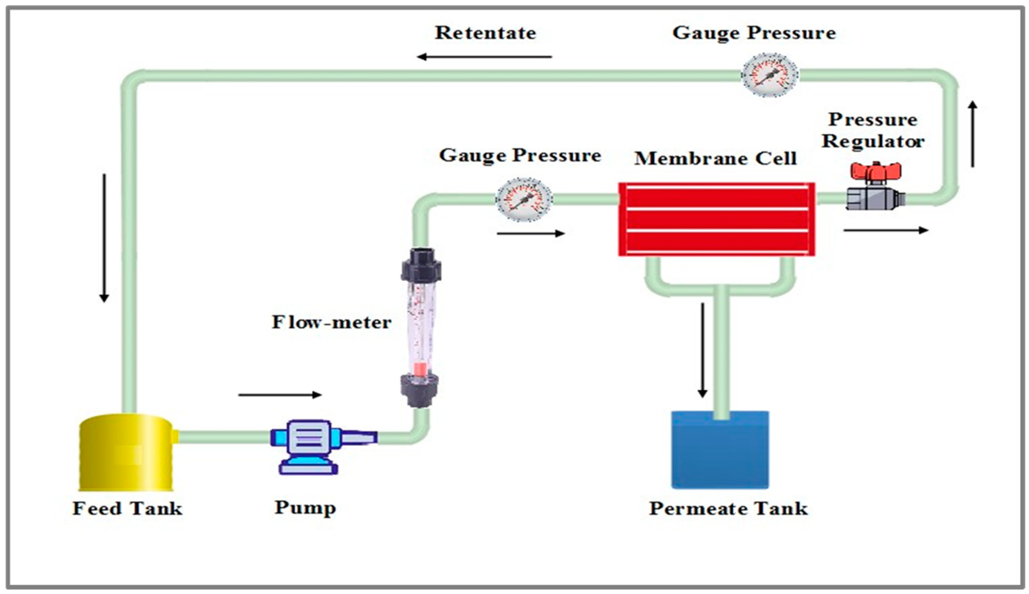
2.3.2. Performance Evaluation of Membranes

Membrane filtration experiments were conducted using a custom-made crossflow system with an effective membrane area of approximately 18.49 cm2 (see Figure 1). The membranes were compacted with DI water at 2 bars for 30 min before each test to ensure steady-state conditions. Subsequently, the pressure was reduced, and all membranes were tested under consistent operating conditions: a transmembrane pressure (TMP) of 1 bar, a flow rate of 0.75 L/min, and room temperature. Each test was performed at least three times per sample, and the average of the recorded data was taken. The permeate flux (J) was calculated using Equation (3):
J = v A s × Δ t
where v is the volume of the collected permeate (L/m2·h), As is the effective surface area of the membrane (m2), and Δt (h) is the time taken to obtain the volume of the collected permeate (L/m2·h).
For membrane separation assessment, tests were conducted using a BSA solution and two synthetic dyes: Congo red and Methyl orange. The BSA feed solution was maintained at a constant concentration of 1000 ppm, while the dye concentrations were 200 ppm for Congo red and 30 ppm for Methyl orange. The feed and permeate samples were collected, and their concentrations were determined using UV spectroscopy. Rejection (R%) was computed using Equation (4) [10]:
R ( % ) = ( 1 c P c f ) × 100
where CP is the concentration of contaminants in the permeate solutions and Cf is the concentration of contaminants in the feed.

3. Results and Discussion

3.1. Characterization of the Manufactured Membranes

3.1.1. Fourier Transform Infrared (FTIR) Spectroscopy

FTIR is a widely utilized and highly regarded characterization tool to identify various functional groups on membrane surfaces and their potential molecular bonds. Figure 2 presents the FTIR spectra for the control and TGF-incorporated membranes at various loading ratios. The spectra for group M, which includes both control PPSU and TGF-incorporated membranes, showed no significant differences with varying the pore former content. This outcome was expected, as TGF, being a water-soluble nanopolymer, was leached entirely out of the membrane structure during the phase separation process. Similarly, the spectra of group S membranes mirrored those of group M, indicating that all solvents were exchanged during membrane formation, leaving no impact on the membrane’s functional groups. The FTIR spectra for all membranes in both groups were identical to that of the neat membrane, exhibiting the characteristic spectra of PPSU. Specifically, the symmetric stretching absorption peak of the O=S=O group in PPSU appeared around 1165 cm−1, while the anti-symmetric stretching peak of the same group was located at 1242 cm−1. Additionally, distinct peaks at 1493 cm−1 and 1590 cm−1 were attributed to the stretching vibrations of the benzene ring (C=C) [20].

3.1.2. Field Emission Scanning Electron Microscopy (FESEM)

FESEM imaging was utilized to investigate the influence of TGF pore former content and solvent type on the cross-sectional morphologies of PPSU membranes (Figure 3). Compared to group S, the imaging for the PPSU membrane prepared with DMAc solvent (group M) revealed a well-formed finger-like microporous structure within the top half of the membrane due to the use of DMAc solvent, which allows for a more controlled phase separation process. This morphology was supported by a denser sponge-like structure at the bottom, with small macrovoid formations (Figure 3A). Conversely, the membrane prepared with NMP solvent exhibited a well-formed finger-like microporous structure throughout the entire membrane cross-section due to the NMP’s quicker evaporation rate and tendency to induce rapid phase separation, which can enhance pore formation, extending from the top to the bottom layer, with some sponge-like structures at the base (Figure 3F). In this case, the pore walls were relatively thin, with a minimal sponge structure randomly distributed and thick skin layer at the top surface, aligning with previous intrinsic PPSU and PES membrane morphologies reported in the literature [21,22].
When TGF was incorporated into the PPSU polymeric matrix, gradual changes in morphology began to emerge based on the additive content. Both groups showed an increase in the number of pores with thinner walls, extending almost from the top to the bottom of the membranes, with only a few dense structures at the bottom (Figure 3B,G). Increasing the pore former content to 4 wt.% further enhanced this observation, resulting in the disappearance of the sponge-like structure in all membranes, regardless of the solvent type (Figure 3C,H). Beyond this pore former content, no significant morphological changes were observed; all membranes were fully integrated throughout their entire structure. These observed morphological changes upon adding the pore former are logically explained by the enhanced thermodynamic instability of the dope solution induced by TGF incorporation. The pore former facilitates better mixing–demixing between solvent and nonsolvent, creating a more porous structure during the phase separation process [23,24]. Indeed, the pore former left the casting film during coagulation, forming more pores with a finger-like structure, as observed in this study (Figure 3D–J).

3.1.3. Atomic Force Microscopy (AFM)

The fabricated membranes’ surface topography and roughness parameters were characterized using atomic force microscopy (AFM). Figure 4 presents AFM images for both group M and group S membranes. In these 3D images, the bright areas correspond to the heights (peaks), while the dark areas indicate the lowest points (valleys) on the surface [25,26]. As shown in Table 2, a clear correlation exists between the roughness parameter values and the different levels of TGF content in the membranes. As can be seen, the pristine PPSU membrane exhibited the highest mean surface roughness amongst all other modified membranes, with values of 75.8 nm for group M and 59.4 nm for group S. However, increasing the TGF content in the polymeric matrix decreased the roughness parameters for both membrane groups. For group M, incorporating 3 wt.% of TGF reduced the mean roughness value (Sa) to 68.1 nm compared to the pristine PPSU membrane.
Meanwhile, a further increase to 4 wt.% TGF caused a significant decrease in the Sa value to 38.1 nm. Beyond this level of TGF content, the roughness parameters remained almost comparable, with values of 28.8 nm and 29.5 nm recorded for the M4 and M5 membranes, respectively. Similarly, the group S membranes exhibited a decreasing trend in roughness values with increasing TGF content, although the roughness values were slightly lower than those of the group M membranes. The Sa values for the group S membranes were 53.1 nm, 27.1 nm, 23.3 nm, and 21.7 nm for the S2, S3, S4, and S5 membranes, respectively. This trend confirms that TGF, as a pore former, could significantly influence surface roughness, resulting in a smoother membrane surface compared to a neat PPSU membrane.

3.1.4. Hydrophilicity Measurements of Membranes
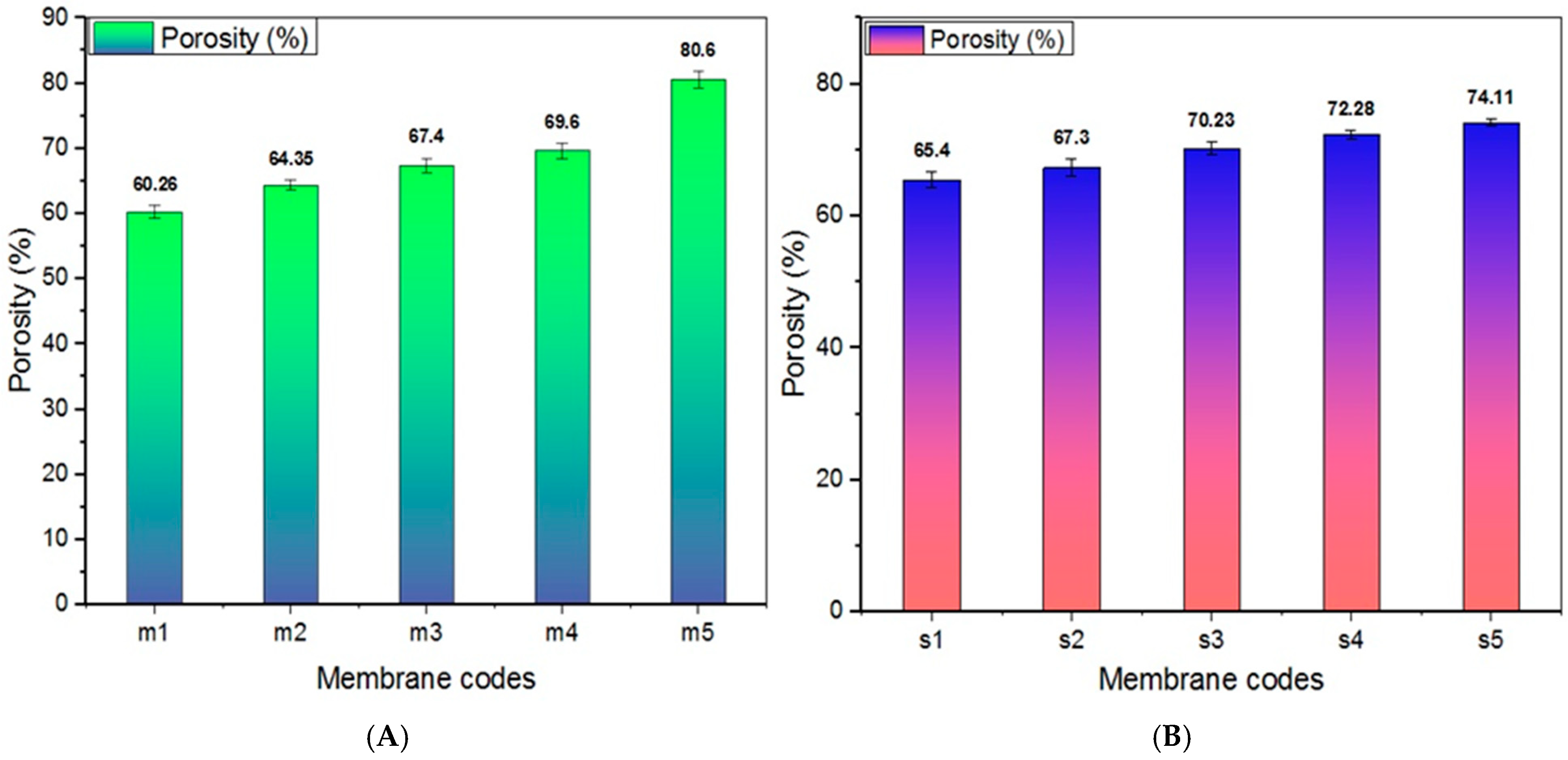
One of the most critical parameters directly linked to the fouling of liquid filtration membranes is surface hydrophilicity, typically measured by the contact angle. Generally, a lower water contact angle indicates higher surface hydrophilicity and vice versa. In this study, the contact angle was measured to assess the influence of pore former content and solvent type on the hydrophilicity of PPSU membranes. The contact angles for PPSU membranes with varying TGF contents (0, 3, 4, 5, and 6 wt.%) for both solvent groups are presented in Figure 5. Pristine membranes are prepared using DMAC and NMP solvents exhibited higher contact angles compared to those with TGF incorporation. Specifically, the average contact angle values were 70.5° for M1 and 65.1° for S1 membranes. Incorporating TGF pore former at different levels in the casting solution showed a slight decline in the contact angle with an increase in the doping mass of TFG, as shown in Figure 5A,B. This suggests that TGF was entirely removed from the membrane structure during the coagulation process, and no significant hydrophilic functional groups were imparted onto the membranes. These results align with the FTIR analysis findings presented earlier in this study.

3.1.5. Porosity

The impact of solvent type and the quantity of TGF pore former within the casting solution on the porosity of PPSU membranes is illustrated in Figure 6A,B. Incorporating 3 wt.% TGF into the PPSU polymer dope solution increased porosity from 60.2% in the neat PPSU to 64.3% in the M1 membrane. As the TGF content increased to 4 wt.%, the porosity escalated to 67.4% for the group M membranes (Figure 6A). The highest porosity was observed at 6 wt.% TGF, reaching 80.6%. By contrast, membranes in group S displayed slightly lower porosity values (Figure 6B). The porosity values for the S2, S3, and S4 membranes were 67.3%, 70.2%, and 72.2%, respectively. At 6 wt.% TGF, the group S membrane achieved its highest porosity value of 74.1%. This proportional increase in porosity is likely attributed to the positive influence of TGF content. These findings align with the FESEM images, indicating that increasing pore density is proportional to the pore former content. The previous literature has noted that incorporating pore formers into polymer solutions can facilitate the formation of a highly porous membrane structure [5]. This observation suggests that the TGF pore former significantly enhances the porosity of PPSU membranes, with the solvent type playing a role in the extent of this enhancement. The increased porosity, facilitated by the pore former, can lead to improved membrane performance, particularly in applications requiring high permeability. The findings underscore the importance of optimizing pore former content to achieve desirable membrane characteristics. The correlation between pore former content and porosity provides valuable insights for future membrane design and fabrication strategies, emphasizing the potential of TGF in developing advanced PPSU membranes with superior structural properties.

3.1.6. Mean Pore Size

The mean pore size and pore distribution play pivotal roles in determining a membrane’s selectivity and permeability. The effect of incorporating TGF within the PPSU polymeric matrix on the mean pore size is illustrated in Figure 7. There is a distinct correlation between the membrane’s pore size and the increasing content of the pore former in the casting solution. For the group M membranes, the pore size for the control PPSU membrane was reported to be 15.1 nm; however, with the inclusion of the pore-forming agent, a marginal increase in pore size was observed, recording 16.8 nm at 3 wt.% TGF. The membrane with the highest pore former concentration of 6 wt.% exhibited a maximum pore size of 31.1 nm (Figure 7A). Similarly, for the group S membranes, the pore sizes corresponding to TGF concentrations of 0%, 3%, 4%, 5%, and 6% were 17.15, 25.09, 25.23, 25.58, and 29.99 nm, respectively (Figure 7B). According to earlier research [10,11], TGF inclusion gradually increased the mean pore size, suggesting that the pore-forming successfully altered the membranes’ pore structure. These findings highlight how important it is to use TGF as a pore former. The size of the pores in the membrane is directly influenced by the rate at which the phases separate throughout the solution process. Essentially, the pore-forming agent facilitates the creation of bigger pores by speeding up the solvent exchange during phase separation. This finding emphasizes how crucial pore formers are for customizing membrane characteristics and making them ideal for particular filtration applications. The performance of the membrane in terms of selectivity and permeability can be improved by fine-tuning the pore size and distribution by varying the amount of TGF in the casting solution. This method offers a calculated route for creating sophisticated membranes with enhanced filtration capacities, effectively meeting various industrial demands.

3.2. Performance of the Membranes

3.2.1. Pure Water Flux

A laboratory-scale crossflow setup was utilized to evaluate the permeation characteristics of PPSU and PPSU/TGF membranes fabricated using two organic solvents at room temperature, with a flow rate of 0.75 L/min and a pressure of 1 bar. Pure water flux (PWF) is directly influenced by membrane surface properties, such as hydrophilicity, roughness, porosity, and pore size [27]. The PWF of PPSU membranes with varying TGF content is depicted in Figure 8A,B. The results demonstrate a substantial enhancement in PWF with increasing TGF content in the casting solution. Specifically, the PWF of PPSU/TGF membranes exhibited a direct and proportional increase with TGF content, ranging from 0 to 6 wt%.
The findings indicate a significant rise in PWF for group M membranes, reaching 71.4 l/m2·h with the addition of 3 wt.% TGF, compared to 54.1 l/m2·h for the pristine PPSU membrane. Further addition of TGF up to 6 wt.% resulted in a peak PWF value of approximately 250.9 l/m2·h for the M5 membrane. This improvement can be attributed to enhancements in surface characteristics, such as increased pore size, porosity, and favorable morphology due to incorporation of the pore-forming agent. Similarly, the group S membranes displayed a comparable trend in water permeability (Figure 8B), where the initial 3 wt.% TGF incorporation increased the PWF to more than double (119 l/m2·h) compared to 48.7 l/m2·h for the neat PPSU membrane. Further increases in TGF content to 4 and 5 wt.% resulted in PWF values of 138.5 and 142.8 l/m2·h, respectively. Meanwhile, incorporating 6 wt.% TGF led to more than a 4.5-fold improvement in the PWF.
Thus, adding TGF particles to the casting solution significantly enhanced the membranes’ pure water permeability (PWP). This improvement is attributed to the beneficial effects of TGF on the membrane surface during the phase inversion process, resulting in increased porosity and mean pore size. These observations are consistent with findings reported in the literature [28].

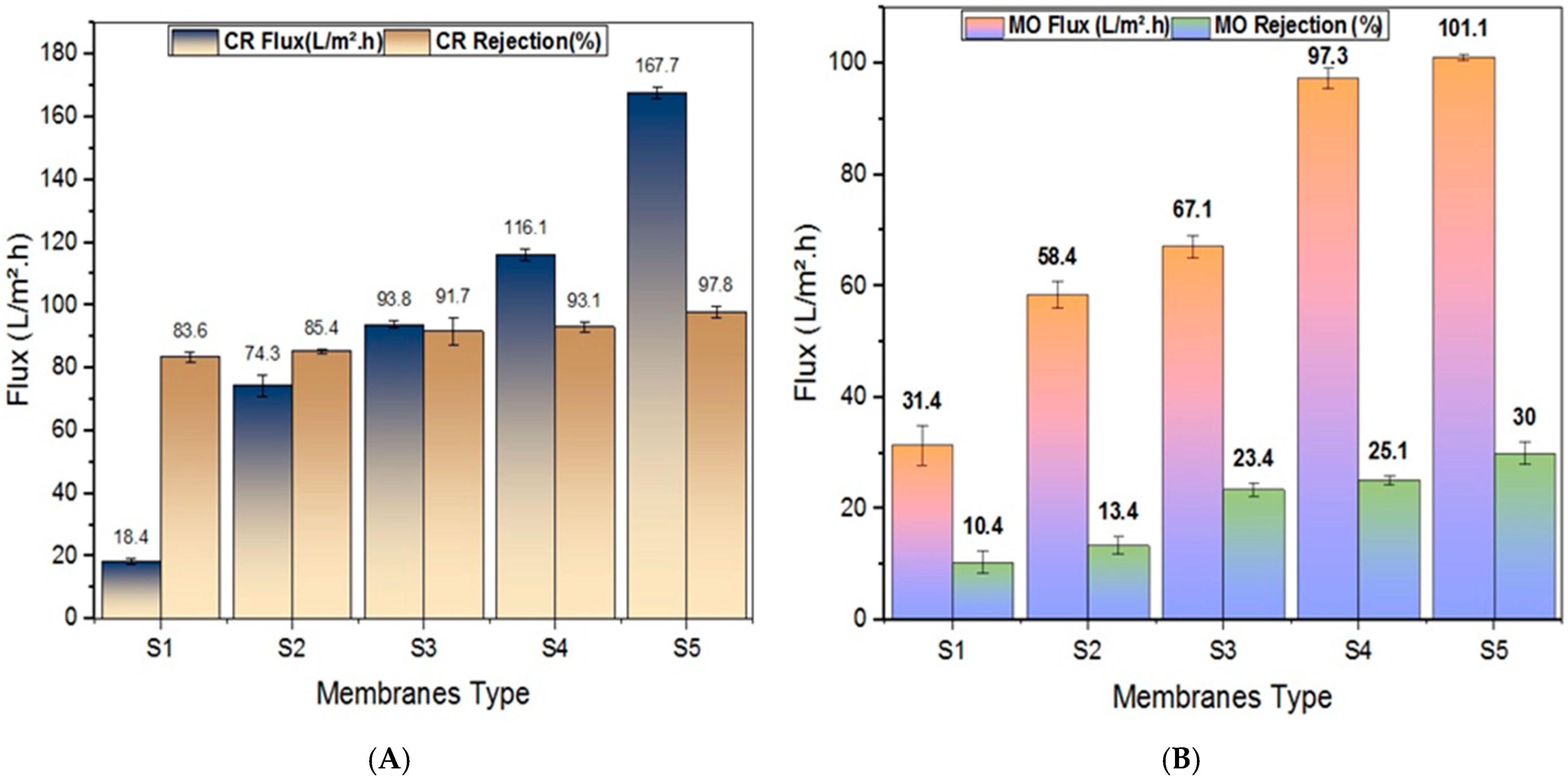
3.2.2. Retention Efficiency of Fabricated Membranes

Retention and solute permeation tests were conducted using two distinct types of foulants: Bovine serum albumin (BSA), a common protein foulant model, and synthetic dyes (Congo red and Methyl orange). The separation efficiency and solute flux for BSA using the group M and group S membranes are presented in Figure 9A,B. Figure 9A illustrates the BSA separation efficiency of PPSU membranes prepared with varying TGF compositions and DMAc solvent (group M). The separation efficiency slightly increased with rising TGF wt.% content in the casting solution, with the highest BSA rejection observed for the membrane prepared with 6 wt.% TGF, showing a rejection ratio of 83.1% compared to 76.1% for the control PPSU membrane. However, this membrane experienced a flux reduction of nearly 56% when the BSA solution was passed through it.
Similarly, group S membranes exhibited comparable retention results, with slightly higher retention capabilities and lower BSA solute flux. The S6 membrane recorded a BSA rejection of 88.1% and a flux of 121.9 l/m2·h. Since the operating conditions were fixed, retention primarily depended on the membrane’s pore size and porosity rather than protein–protein and protein–membrane interactions. Compared to previous studies, the enhanced porosity of the prepared PPSU/TGF membranes significantly contributed to their BSA separation efficiency (Table 3).
The retention performance varied depending on the membranes’ pore size distribution. During the initial filtration stage, the wide range of pore sizes in the M6 and S6 membranes facilitated simultaneous BSA adsorption within the pores and on the membrane surface. As filtration progressed, BSA adsorption continued on the already fouled membrane resulted in a thicker protein layer accumulation over the initial monolayer. Consequently, membranes with a more extensive structure exhibited slightly higher retention.
Dye solutions containing Congo red and Methyl orange were utilized to evaluate the influence of TGF content on the removal efficiency of PPSU membranes. Figure 10A,B illustrates the permeation fluxes and membrane rejection for group M, while Figure 11A,B pertains to group S membranes.
As shown in Figure 11, the retention capacity of all TGF-modified membranes was superior to that of the pure PPSU membrane. The separation efficiency for both dyes increased with higher TGF content in the casting solution. Incorporating TGF into the membrane structure enhanced the retention efficiency of the PPSU membrane from 70.2% to 72% against Congo red (CR) solution with the addition of just 3 wt.% TGF. A further increase to 4 wt.% TGF resulted in a retention efficiency of 75.7%. The membrane that was prepared with 6 wt.% TGF exhibited the highest retention values of approximately 81.5% for CR and 20.9% for Methyl orange (MO) dye solutions, compared to the control PPSU membrane, which showed 70.2% and 5%, respectively. Compared to MO dye, the higher separation efficiency against CR dye was attributed to the larger molecular size of CR, which restricts more molecules from passing through the membrane, thereby increasing separation efficiency [33]. Additionally, the flux decline observed with dye solutions was significantly less than that with BSA solution due to differing fouling mechanisms associated with the nature of the foulants. Only a slight flux decline (around 20–25%) was noted for both dye solutions.
Similarly, the group S membranes displayed comparable separation behavior against both dye solutions with slight variations. Generally, these membranes exhibited higher retention potentials than the group M membranes. For instance, the S6 membrane achieved nearly complete retention (97.8%) against CR dye compared to 81.5% for the M6 membrane. Moreover, the S6 membrane showed improved retention against MO solution, capable of rejecting 30% compared to the M6 membrane, due to the smaller pore size of the group S membranes compared to those of the group M membranes.
Since the modified membranes had better porous structures than the unmodified membranes in both groups, their dye removal and solution flux were higher. Modified membranes demonstrated a strong adsorption affinity for cationic and azo dyes, namely Methyl orange and Congo red, which have a positive surface charge at neutral pH. An important part of removing the dyes Methyl orange and Congo red was due to electrostatic interactions and non-covalent bonds like hydrogen bonds [34,35].

4. Conclusions

This study utilized a novel water-soluble polymeric nanopolymer, terephthalic-co-glycerol-g-fumaric acid (TGF), as a pore former to modify a PPSU ultrafiltration membrane for wastewater separation applications. The investigation focused on assessing the impact of incorporating varying TGF content (0–6 wt.%) on the surface and morphological structure of the membrane using two solvents. The effect of TGF addition to PPSU membranes was systematically characterized using FTIR, CA, SEM, and AFM techniques. The results revealed that incorporating TGF into PPSU altered the surface topography of the membranes, resulting in a smoother surface. The FTIR spectra did not detect TGF, indicating that the water-soluble pore former was completely leached out during the phase separation.
Furthermore, no significant improvement in membrane hydrophilicity was observed due to this leaching. However, increasing the TGF content within the polymeric matrix formed a more porous structure with elongated finger-like pores. The influence of TGF was evident in the pore size and porosity of the membranes, with pore size nearly doubling compared to neat PPSU. Porosity also improved from 10% to 20%, depending on the amount of TGF and the solvent used.
The overall performance of the membranes was evaluated against BSA and synthetic dye solutions. The results showed that at 6 wt.% TGF content, PWF flux experienced a significant increase from 54 to 250.9 LMH for group M and from 48 to 220 LMH for group S. Separation performance tests indicated that TGF enhanced BSA separation at higher loading (6 wt.%) compared to unmodified PPSU membrane and showed high retention capacity against CR while maintaining very low flux decline. Additionally, the fabricated membrane was capable of separating MO dye solution despite its small molecular size, without significant flux loss. These results highlight the potential advantages of the TGF/PPSU membrane’s proven permeation and separation properties, emphasizing its applicability for applications involving the separation of proteins and synthetic dyes.

Author Contributions

H.A.A.: conceptualization, investigation, methodology, and writing—review. Q.F.A.: conceptualization, investigation, methodology, validation, visualization, writing—review and editing. S.A.-S.: conceptualization, methodology, formal analysis, validation, writing—review and editing. F.H.A.: conceptualization, investigation, methodology, validation, visualization and writing—review. H.M.: formal analysis and validation. R.A.A.-J.: formal analysis and validation. F.R.: investigation, formal analysis and validation. G.C.: investigation, formal analysis and validation. G.D.L.: investigation, formal analysis and validation. A.F.: investigation, formal analysis, resources and validation. All authors have read and agreed to the published version of the manuscript.

Funding

This research received no external funding.

Data Availability Statement

The data presented in this study are available on request from the corresponding author.

Acknowledgments

The authors wish to acknowledge use of facilities (FTIR, CA, SEM and AFM) within Institute on Membrane Technology (ITM-CNR) National Research Council, University of Calabria, Rende, Cosenza, Italy.

Conflicts of Interest

The authors declare no conflicts of interest.

References

  1. Shannon, M.A.; Bohn, P.W.; Elimelech, M.; Georgiadis, J.G.; Mariñas, B.J.; Mayes, A.M. Science and technology for water purification in the coming decades. Nature 2008, 452, 301–310. [Google Scholar] [CrossRef] [PubMed]
  2. Heidi, L.R.; Priscilla, G.L.B.; Emmanuel, I. Metal Nanoparticle Modified Polysulfone Membranes for Use in Wastewater Treatment: A Critical Review. J. Surf. Eng. Mater. Adv. Technol. 2012, 2, 183–193. [Google Scholar]
  3. Malik, T.; Razzaq, H.; Razzaque, S.; Nawaz, H.; Siddiqa, A.; Siddiq, M.; Qaisar, S. Design and synthesis of polymeric membranes using water-soluble pore formers: An overview. Polym. Bull. 2019, 76, 4879–4901. [Google Scholar] [CrossRef]
  4. Al Aani, S.; Wright, C.J.; Atieh, M.A.; Hilal, N. Engineering nanocomposite membranes: Addressing current challenges and future opportunities. Desalination 2017, 401, 1–15. [Google Scholar] [CrossRef]
  5. Nazarova, O.; Chernova, E.; Dobrodumov, A.; Zolotova, Y.; Bezrukova, M.; Nekrasova, T.; Vlasova, E.; Panarin, E. New water-soluble copolymers of 2-methacryloyloxyethyl phosphorylcholine for surface modification. J. Appl. Polym. Sci. 2021, 138, 50272. [Google Scholar] [CrossRef]
  6. Alayande, A.B.; Obaid, M.; Yu, H.W.; Kim, I.S. High-flux ultrafiltration membrane with open porous hydrophilic structure using dual pore formers. Chemosphere 2019, 227, 662–669. [Google Scholar] [CrossRef]
  7. Roy, K.J.; Anjali, T.V.; Sujith, A. Poly (vinyl chloride) asymmetric membrane modified with poly (ethylene glycol): Effect of additive concentration on the morphology and performance. Polym.-Plast. Technol. Eng. 2017, 56, 1017–1025. [Google Scholar] [CrossRef]
  8. Farjami, M.; Vatanpour, V.; Moghadassi, A. Influence of the various pore former additives on the performance and characteristics of the bare and EPVC/boehmite nanocomposite ultrafiltration membranes. Mater. Today Commun. 2019, 21, 100663. [Google Scholar] [CrossRef]
  9. Rabiee, H.; Shahabadi, S.M.; Mokhtare, A.; Rabiei, H.; Alvandifar, N. Enhancement in permeation and antifouling properties of PVC ultrafiltration membranes with addition of hydrophilic surfactant additives: Tween-20 and Tween-80. J. Environ. Chem. Eng. 2016, 4, 4050–4061. [Google Scholar] [CrossRef]
  10. Rashid, K.T.; Alayan, H.M.; Mahdi, A.E.; AL-Baiati, M.N.; Majdi, H.S.; Salih, I.K.; Ali, J.M.; Alsalhy, Q.F. Novel Water-Soluble Poly(Terephthalic-co-Glycerol-gFumaric Acid) Copolymer Nanoparticles Harnessed as Pore Formers for Polyethersulfone Membrane Modification: Permeability–Selectivity Tradeoff Manipulation. Water 2022, 14, 1507. [Google Scholar] [CrossRef]
  11. Al Hachim, Z.S.; Ridha, A.M.; Al-Baiati, M.N.; Alsalhy, Q.F.; Majdi, H.S. Sustainable Modification of Polyethersulfone Membrane with Poly(Maleic Anhydride-Co-Glycerol) as Novel Copolymer. Water 2022, 14, 1207. [Google Scholar] [CrossRef]
  12. Shanker, U.; Rani, M.; Jassal, V. Degradation of Hazardous Organic Dyes in Water by Nanomaterials. Environ. Chem. Lett. 2017, 15, 623–642. [Google Scholar] [CrossRef]
  13. Ahmad, A.; Mohd-Setapar, S.H.; Chuong, C.S.; Khatoon, A.; Wani, W.A.; Kumar, R.; Rafatullah, M. Recent advances in new generation dye removal technologies: Novel search for approaches to reprocess wastewater. RSC Adv. 2015, 5, 30801–30818. [Google Scholar] [CrossRef]
  14. Mojsov, K.D.; Andronikov, D.; Janevski, A.; Kuzelov, A.; Stevan, G. The application of enzymes for the removal of dyes from textile effluents. Adv. Technol. 2016, 5, 81–86. [Google Scholar] [CrossRef]
  15. Katheresan, V.; Kansedo, J.; Lau, S.Y. Efficiency of various recent wastewater dye removal methods: A review. J. Environ. Chem. Eng. 2018, 6, 4676–4697. [Google Scholar] [CrossRef]
  16. Ziane, S.; Bessaha, F.; Marouf-Khelifa, K.; Khelifa, A. Single and binary adsorption of reactive black 5 and Congo red on modified dolomite: Performance and mechanism. J. Mol. Liq. 2018, 249, 1245–1253. [Google Scholar] [CrossRef]
  17. Soriano, J.J.; Mathieu-Denoncourt, J.; Norman, G.; de Solla, S.R.; Langlois, V.S. Toxicity of the azo dyes Acid Red 97 and Bismarck Brown Y to Western clawed frog (Silurana tropicalis). Environ. Sci. Pollut. Res. 2014, 21, 3582–3591. [Google Scholar] [CrossRef]
  18. Alsalhy, Q.F.; Rashid, K.T.; Ibrahim, S.S.; Ghanim, A.H.; Van der Bruggen, B.; Luis, P.; Zablouk, M. Poly(vinylidene fluoride-co-hexafluoropropylene) (PVDF-co-HFP) hollow fiber membranes prepared from PVDF-co-HFP/PEG-600Mw/DMAC solution for membrane distillation. J. Appl. Polym. Sci. 2013, 129, 3304–3313. [Google Scholar] [CrossRef]
  19. Al-Araji, D.D.; Al-Ani, F.H.; Alsalhy, Q.F. Modification of polyethersulfone membranes by Polyethyleneimine (PEI) grafted Silica nanoparticles and their application for textile wastewater treatment. Environ. Technol. 2023, 44, 3033–3049. [Google Scholar] [CrossRef]
  20. Ali, A.M.; Rashid, K.T.; Yahya, A.A.; Majdi, H.S.; Salih, I.K.; Yusoh, K.; Alsalhy, Q.F.; AbdulRazak, A.A.; Figoli, A. Fabrication of Gum Arabic-Graphene (GGA) Modified Polyphenylsulfone (PPSU) Mixed Matrix Membranes: A Systematic Evaluation Study for Ultrafiltration (UF) Applications. Membranes 2021, 11, 542. [Google Scholar] [CrossRef]
  21. Al-Ani, D.M.; Al-Ani, F.H.; Alsalhy, Q.F.; Ibrahim, S.S. Preparation and characterization of nanofiltration membranes from PPSU-PES polymer blend for dyes removal. Chem. Eng. Commun. 2021, 208, 41–59. [Google Scholar] [CrossRef]
  22. Shawket, A.N.; Ali, N.S.; Alsalhy, Q.F. Systematic study for a comprehensive evaluation of PPSU modified with ZnO for ultrafiltration membranes: Morphological characteristics and performance. Desalin. Water Treat. 2023, 284, 27–38. [Google Scholar] [CrossRef]
  23. Saljoughi, E.; Amirilargani, M.; Mohammadi, T. Effect of PEG additive and coagulation bath temperature on the morphology, permeability and thermal/chemical stability of asymmetric CA membranes. Desalination 2010, 262, 72–78. [Google Scholar] [CrossRef]
  24. Ma, Y.; Shi, F.; Wang, Z.; Wu, M.; Ma, J.; Gao, C. Preparation and characterization of PSf/clay nanocomposite membranes with PEG 400 as a pore forming additive. Desalination 2012, 286, 131–137. [Google Scholar] [CrossRef]
  25. Velu, S.; Rambabu, K.; Monash, P.; Sharma, C. Improved hydrophilic property of PES/PEG/MnCO3 blended membranes for synthetic dye separation. Int. J. Environ. Stud. 2018, 75, 592–604. [Google Scholar] [CrossRef]
  26. Jalal Sadiq, A.; Shabeeb, K.M.; Khalil, B.I.; Alsalhy, Q.F. Effect of embedding MWCNT-g-GO with PVC on the performance of PVC membranes for oily wastewater treatment. Chem. Eng. Commun. 2020, 207, 733–750. [Google Scholar] [CrossRef]
  27. Ma, Y.; Shi, F.; Ma, J.; Wu, M.; Zhang, J.; Gao, C. Effect of PEG additive on the morphology and performance of polysulfone ultrafiltration membranes. Desalination 2011, 272, 51–58. [Google Scholar] [CrossRef]
  28. Koulivand, H.; Shahbazi, A.; Vatanpour, V. Fabrication and characterization of a high-flux and antifouling polyethersulfone membrane for dye removal by embedding Fe3O4-MDA nanoparticles. Chem. Eng. Res. Des. 2019, 145, 64–75. [Google Scholar] [CrossRef]
  29. Xiao, S.; Huo, X.; Fan, S.; Zhao, K.; Yu, S.; Tan, X. Design and synthesis of Al-MOF/PPSU mixed matrix membrane with pollution resistance. Chin. J. Chem. Eng. 2021, 29, 110–120. [Google Scholar] [CrossRef]
  30. Isloor, A.M.; Nayak, M.C.; Prabhu, B.; Ismail, N.; Ismail, A.F.; Asiri, A.M. Novel polyphenylsulfone (PPSU)/nano tin oxide (SnO2) mixed matrix ultrafiltration hollow fiber membranes: Fabrication, characterization and toxic dyes removal from aqueous solutions. React. Funct. Polym. 2019, 139, 170–180. [Google Scholar] [CrossRef]
  31. Dehban, A.; Kargari, A.; Ashtiani, F.Z. Preparation and optimization of antifouling PPSU/PES/SiO2 nanocomposite ultrafiltration membranes by VIPS-NIPS technique. J. Ind. Eng. Chem. 2020, 88, 292–311. [Google Scholar] [CrossRef]
  32. Ghadhban, M.Y.; Majdi, H.S.; Rashid, K.T.; Alsalhy, Q.F.; Lakshmi, D.S.; Salih, I.K.; Figoli, A. Removal of dye from a leather tanning factory by flat-sheet blend ultrafiltration (UF) membrane. Membranes 2020, 10, 47. [Google Scholar] [CrossRef]
  33. Hou, T.; Guo, K.; Wang, Z.; Zhang, X.-F.; Feng, Y.; He, M.; Yao, J. Glutaraldehyde and polyvinyl alcohol crosslinked cellulose membranes for efficient methyl orange and Congo red removal. Cellulose 2019, 26, 5065–5074. [Google Scholar] [CrossRef]
  34. Saleh, T.A.; Al-Absi, A.A. Kinetics, isotherms and thermodynamic evaluation of amine functionalized magnetic carbon for methyl red removal from aqueous solutions. J. Mol. Liq. 2017, 248, 577–585. [Google Scholar] [CrossRef]
  35. Walters, M.; Al Aani, S.; Esteban, P.P.; Williams, P.M.; Oatley-Radcliffe, D.L. Laser Doppler electrophoresis and electro-osmotic flow mapping for the zeta potential measurement of positively charged membrane surfaces. Chem. Eng. Res. Des. 2020, 159, 468–476. [Google Scholar] [CrossRef]
Figure 1. Schematic diagram for the manufactured UF membrane system.
Chemengineering 09 00012 g001
Figure 2. FTIR spectra for group M and group S membranes.
Chemengineering 09 00012 g002
Figure 3. FESEM cross section for (A) pure PPSU membrane and solvent DMAC without TGF, (B) with 3% of TGF/PPSU and solvent DMAC, (C) with 4% of TGF/PPSU and solvent DMAC, (D) with 5% of TGF/PPSU and solvent DMAC, (E) with 6% of TGF/PPSU and solvent DMAC, (F) pure PPSU membrane and solvent NMP without TGF, (G) with 3% of TGF/PPSU and solvent NMP, (H) with 4% of TGF/PPSU and solvent NMP, (I) with 5% of TGF/PPSU and solvent NMP, (J) with 6% of TGF/PPSU and solvent NMP.
Chemengineering 09 00012 g003aChemengineering 09 00012 g003bChemengineering 09 00012 g003c
Figure 4. AFM for (A) pure PPSU membrane and solvent DMAC without TGF, (B) with 3% of TGF/PPSU and solvent DMAC, (C) with 4% of TGF/PPSU and solvent DMAC, (D) with 5% of TGF/PPSU and solvent DMAC, (E) with 6% of TGF/PPSU and solvent DMAC, (F) pure PPSU membrane and solvent NMP without TGF, (G) with 3% of TGF/PPSU and solvent NMP, (H) with 4% of TGF/PPSU and solvent NMP, (I) with 5% of TGF/PPSU and solvent NMP, (J) with 6% of TGF/PPSU and solvent NMP.
Chemengineering 09 00012 g004aChemengineering 09 00012 g004b
Figure 5. Contact angle results for (A) group M membranes and (B) group S membranes.
Chemengineering 09 00012 g005
Figure 6. Porosity test results for (A) group M membranes and (B) group S membranes.
Chemengineering 09 00012 g006
Figure 7. Mean pore size for (A) group M membranes and (B) group S membranes.
Chemengineering 09 00012 g007
Figure 8. Pure water flux permeability test results for (A) group M membranes and (B) group S membranes.
Chemengineering 09 00012 g008
Figure 9. BSA flux application results for (A) group M membranes and (B) group S membranes.
Chemengineering 09 00012 g009
Figure 10. Permeation flux and rejection results of (A) Congo red and (B) Methyl orange group for group M membranes.
Chemengineering 09 00012 g010
Figure 11. Permeation flux and rejection results of (A) Congo red and (B) Methyl orange group for group S membranes.
Chemengineering 09 00012 g011
Table 1. Casting solutions for membranes.
SamplePPSU (%)DMAc (%)NMP (%)TGF (%)
M11486-0
M21486-3
M31486-4
M41486-5
M51486-6
S114-860
S214-863
S314-864
S414-865
S514-866
Table 2. Parameters describing the roughness of the surface obtained from AFM images.
Membrane SampleSa (nm)Sz (nm)Sq (nm)
M175.81397.74100.80
M268.13448.6999.06
M338.11344.9753.57
M428.81177.2137.61
M529.5158.83.77
S159.47302.0279.31
S253.19444.1980.14
S327.14256.9339.35
S423.35210.7432.43
S521.73119.4928.74
Table 3. Comparison of PPSU membranes with other membranes reported in the literature.
MembraneFoulant TypePermeability (L/m2·h)Foulant (Flux L/m2·h)Rejection (%) Reference
PPSU/CAUBSA47.730.6-[29]
PPSUBSA203042[30]
PPSU (PS-0) BSA62.713.5-[30]
PPSU/SiO2 BSA76.5-82.01[31]
PPSUDrupel Black NT 23-84[32]
PSSU/TGF
(Solvent: DMAc)
BSA250.9 140.683.1This work
PSSU/TGF
(Solvent: NMP)
BSA220121.9 88.1
Disclaimer/Publisher’s Note: The statements, opinions and data contained in all publications are solely those of the individual author(s) and contributor(s) and not of MDPI and/or the editor(s). MDPI and/or the editor(s) disclaim responsibility for any injury to people or property resulting from any ideas, methods, instructions or products referred to in the content.

