Abstract
In this study, the poisoning effects of cerium oxide () as the contaminant on the performance of proton exchange membrane fuel cells (PEMFCs) are evaluated. An experimental setup was developed to analyze the performance characteristic (I-V) curves in contaminated and non-contaminated conditions. Focused ion-beam scanning electron microscopy (FIB-SEM) cross-section images were obtained as an input for the energy dispersive X-ray (EDX) analysis. The results of the EDX analysis verified the presence of in the contaminated membrane electrode assembly (MEA), in addition to fluorine and sulfur. EDX analysis also revealed that as a result of contamination, sulfur and fluorine would be distributed all around the MEA, instead of being only in the membrane. The results illustrate that hydrofluoric acid (HF), sulfuric acid (), and fluorinated polymer fragments are released, which enhance the crossover of the reactant gases through the membrane, hence reducing the cell’s performance. The I-V characteristic curves proved that the non-contaminated PEMFC setup had double the performance of the contaminated PEMFC.
1. Introduction
Proton exchange membrane fuel cells (PEMFCs) are known as efficient electrochemical devices that use hydrogen to generate electricity without greenhouse gas (GHG) emissions [1]. This environmentally friendly device can be considered an alternative to conventional fossil fuel-based engines [2]. Compared to other renewable energies such as solar and wind, which are unstable and intermittent [3], PEMFCs can work continuously in a stable manner. The required hydrogen for PEMFCs can be provided through different sources such as integration with electrolyzers [4]. Although the efficiency of this electrochemical device is high (around 50–60%), the performance can be further improved by preventing possible contaminations [5].
Mass transport issues, mitigating reaction sites, and the reduction in the ionic conductivity of ionomers are the main adverse effects of contaminants in the PEMFC [6]. Contaminants endanger the chemical stability of the membrane electrode assembly (MEA), which should be controlled deliberately to achieve higher durability [7]. Additionally, different types of contaminants have their specific impacts on the performance of the PEMFC [8]. PEMFC contaminants can be categorized into fuel impurities, air impurities, and cationic ions.
Fuel impurities such as , , and , which are the results of hydrogen reformation, reduce kinetic reaction rates by involving active sites [9]. Hydrogen sulfide () deactivates Pt particles and results in the cell’s degradation. The presence of and result in the occupation of the Pt available surface area, hence lowering the hydrogen oxidation reaction (HOR) [10]. The existence of ammonia in natural gas also results in the formation of as a fuel impurity, decreasing the ionic conductivity of the catalyst layer (CL) and the membrane. Bilondi et al. [11] performed a two-dimensional numerical study to evaluate the impacts of CO as the contaminant. Results indicate that pre-mixing the hydrogen with 15 ppm of CO can reduce the performance by 30% in 30 min.
The main sources of the air impurities are the exhaust of automobiles and factories such as nitrogen oxides (), sulfur oxides (), carbon oxides (), and ozone [12]. Toluene was also considered an air impurity by Li et al. [13] in different operating conditions and Pt loadings. EIS measurements indicate that although toluene contamination has a negligible impact on the membrane resistance, it increases the kinetic and mass transfer resistances. In another study, Li et al. [14,15] also demonstrated that chlorine can be harmful both in anodes and cathodes due to blocking active sites of Pt in the CL.
Cationic ions such as , , , , and result in the corrosion of the fuel cell stack. Li et al. [16] evaluated the effects of contamination at different concentrations and operating temperatures. The results indicate that lower temperatures lead to higher adsorption of on the Pt catalyst surface, hence reducing the oxygen reduction reaction (ORR) rate [17]. Li et al. [18] also showed that 5 ppm of and 5 ppm of reduce the performance by 65 mV in 282 h, and 174 mV in 191 h, respectively. Jia et al. [19] analyzed the effects of cationic contamination on the mechanical properties of the Nafion® perfluorosulfonic acid (PFSA) membranes at different temperatures. The results indicate that the enhancement of water absorption and temperature lead to lower values of the elastic moduli of the membrane. However, the higher radius of the exchanged cation results in the higher elastic moduli of the membrane. Although there have been many studies evaluating the harmful effects of contaminants, further analyses are needed to consider the resulting microstructural changes and performance degradation in PEMFCs.
Advanced imaging technologies can be used to perform the microstructural analysis of the PEMFC. The formation of water in the gas diffusion layer (GDL) and the CL has been analyzed by neutron imaging to improve water management [20]. Minard et al. [21] also used magnetic resonance imaging (MRI) to predict gas manifold flooding. Although these imaging techniques are appropriate to detect the formation of water in the cell, focused ion beam scanning electron microscopy (FIB-SEM) images can be used to provide details about the microstructure of the MEA [22]. Using FIB-SEM images, energy dispersive X-ray analysis (EDX) can be applied to detect the existing elements in the microstructure [23].
In this study, particles were injected in an experimental setup to evaluate the performance of the PEMFC after and before contamination. As a result of contamination, a sulfonic acid group in the membrane was released and created radical sulfur in the CL, hence causing higher degradation. The I-V characteristic curves of the contaminated and non-contaminated systems were compared to show the degrading impacts of excess cerium particles. Although there have been studies to predict cerium migration during accelerated tests, further studies are needed to characterize performance using microscope imaging and experimental tests in the presence of cerium as a contaminant. FIB-SEM cross-section images were obtained for the contaminated and non-contaminated MEAs followed by EDX analyses to detect the contaminants. Thus, the novelties of the current study can be considered as the experimental investigation of the I-V characteristics of the contaminated and non-contaminated PEMFC in addition to the microstructural analysis using FIB-SEM and EDX.
2. Materials and Methods
To compare the I-V characteristic curves, an experimental setup was developed based on Figure 1. Measurements were obtained with cathode and anode flow rates of 7 (nL/min) and 2.1 (nL/min), respectively, with the corresponding stoichiometric ratio of 2 and 1.4 on the cathode and anode. The back pressure of the gases was also 1 bar gauge pressure, while the average operating temperature was 75 °C. After obtaining the I-V curves of the PEMFC in the non-contaminated conditions, 4 ppm of particles were injected to compare the results. It is noteworthy to mention that a complete PEMFC setup similar to Figure 1 is needed to characterize the impact of any type of contaminant. Different types of contaminants may be harmful for different parts of a stack. Although the impact of cerium (IV) contaminants is mainly on the membrane, only ex situ experiments of the membrane to observe its chemical stability are not enough, and a setup similar to Figure 1 is required to obtain the characteristic curves. In this study, was injected to the system, since is more probable to be in the feed gases rather than cerium (IV). Once I-V characteristic curves of the contaminated and non-contaminated cells are obtained, FIB-SEM cross-section imaging helps to detect the distribution of the contaminants and the existence of different elements in the membrane and CL.
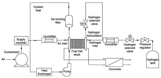
Figure 1.
A schematic of the required system to obtain the I-V characteristic curves in contaminated and non-contaminated PEMFCs.
The samples needed for the microscope imaging were the membrane electrode assemblies (MEAs) provided by the 3M company with a thickness of 14 and catalyst loading of 0.25/0.05 on the cathode/anode side. Similar to the membranes with perfluorinated sulfonic acid [24] and Nafion [25] membranes that have a sulfonic acid group () in their structure, the exposure of the membranes provided by the 3M company to the humidified environment or liquid water enhanced the amount of water molecules associated with each sulfonic acid group. The MEA samples were embedded in a resin to perform the FIB-SEM cross-section imaging. The resin was a mixture of epoxy embedding medium (diglycidyl ether of bisphenol A) with two different hardeners, DDSA (2-dodecenylsuccinic anhydride) and MNA (methylnadic anhydride), which were mixed with DPM-30 [2,4,6-tris(dimethylaminomethyl)phenol] as the accelerator, using 0.4 gr of cobalt (II) acetylacetonate nanoparticles to improve the contrast of the images; all were provided by Sigma Aldrich.
The samples were impregnated with the resin under vacuum to be pressurized (3 MPa) for 20 min, and heated afterward in an oven at 60 °C for 12 h. The surfaces for analyses were cut by a diamond wire, polished by abrasive plates down to 0.1 , and gold-coated (20 nm).
FIB-SEM cross-section images were obtained with a focused ion beam (LMIS Ga+ source) at 1 nA (Zeiss Crossbeam 540). Milling and imaging were performed at a stage tilt of 54°, i.e., the coincidence point of the electron and ion beams. Signals from the Everhart-Thornley secondary electron secondary ion (SESI) detector and the energy-selective backscattered (EsB) detector were recorded for each section.
3. Results
The water flux from the inlet of the cell to the outlet of the PEMFC generates in-plane cerium gradients in fully humidified operations, hence increasing the cerium migration from the membrane to the CL [26]. Once cerium exists in the membrane, it reduces the cell’s degradation by neutralizing reactive radical species, which were generated by electrochemical fuel cell processes, before they attack the ionomer. Radical scavenging is initiated when cerium (III) ions are oxidized by hydroxyl radicals to form tetravalent (IV) ions and water. Based on the conclusions given by Baker et al. [26], in this condition, the thickness of the membrane will be reduced and local pinholes will be generated. As an outcome, hydrofluoric acid (HF), sulfuric acid (), and fluorinated polymer fragments will be released, which enhances the crossover of the reactant gases through the membrane, hence reducing the cell’s performance. Successful cerium stabilization increases PEMFC durability and minimizes performance losses. Figure 2 illustrates the degrading effects of as the contaminant using the I-V characteristic curves.
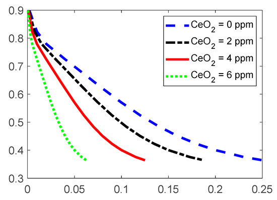
Figure 2.
The obtained experimental I-V characteristic curve of the contaminated and non-contaminated PEMFC. Noted that CeO2 = 6 ppm was not measured in this study, and it is an estimation from the contamination by CeO2 = 2 ppm and CeO2 = 4 ppm.
As shown in Figure 2, higher values of the particles lead to performance losses. These performance losses are attributed to reduced proton conductivity and enhanced mean proton transport length in the CL ionomer. In this condition, the operation of the PEMFC is still possible; however, performance losses will be observed. It should be noted that the proposed experimental setup only detects the impact of the contaminants on the overall output performance such as the I-V characteristic curve. The suggested post-processing analysis using SEM imaging and EDX analysis also only determines the existence of the contaminants, and the values of the produced sulfur radical in the CL should be determined using other methods. Moreover, Figure 3 shows the FIB-SEM cross-section images of the contaminated and non-contaminated MEAs that are used for EDX analysis. Figure 3 also illustrates that the contamination of the membrane does not lead to the decomposition of the membrane PTFE backbone.
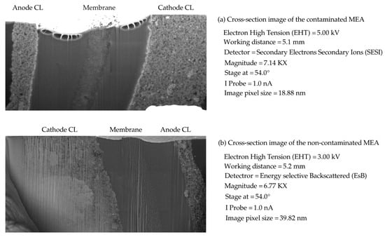
Figure 3.
FIB-SEM cross-section images of the contaminated and non-contaminated MEAs: (a) cross-section image of the contaminated MEA, (b) cross-section image of the non-contaminated MEA.
Figure 4 presents the results of EDX analyses on the obtained cross-section images of Figure 3. Figure 4a shows the existing elements in the contaminated MEA sample. Gallium (Ga) corresponds to the Ga beam used to perform the FIB-SEM imaging, while a gold (Au) coating was applied on the surface of the samples to prevent the charging effects of the electrons. Cobalt (Co) nanoparticles were also added to the embedding resin to improve the contrast of the FIB-SEM images. Compared to Figure 4b, it is clear that the only difference between the contaminated and non-contaminated samples is related to the cerium nanoparticles. Based on Figure 4a, which presents the EDX analysis of the contaminated MEA, there are peaks of the characteristic x-rays at 4.839 keV and 0.883 keV that are related to cerium. These two peaks cannot be seen in Figure 4b, which is representative of the non-contaminated MEA. Previous studies have already indicated that the cerium contaminant creates pinholes in the membrane and releases sulfuric acid and hydrofluoric acid [27]. Thus, sulfur and fluorine are distributed in all parts of the MEA, while they were only in the membrane before contamination by .
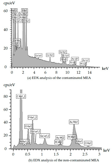
Figure 4.
EDX analyses of the contaminated and non-contaminated samples of MEAs: (a) EDX analysis of the contaminated MEA and (b) EDX analysis of the non-contaminated MEA.
It should be noted that the created pinholes are of nanometer size and it is possible to observe them using transmission electron microscopy (TEM); since the milling process to prepare the cross-sections in FIB-SEM imaging destroys the pinholes and dislocations, local pinholes have not been observed in this study. 0 illustrates the distribution of the sulfur and fluorine in both contaminated and non-contaminated (4 ppm of ) samples using EDX analysis. As shown in Figure 5, the concentration of sulfur and fluorine is increased in the CL after contamination, which leads to performance losses especially in the case of sulfur contamination. Baker et al. [27] already concluded the formation of sulfuric acid and hydrofluoric acid, which was not verified by experimental evidence. In this regard, advanced spectroscopy methods should be used in future studies to detect the created acids.
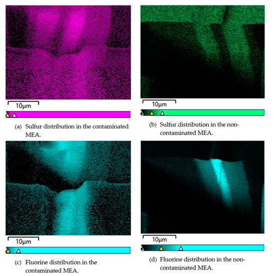
Figure 5.
The distribution of sulfur and fluorine in both contaminated and non-contaminated (4 ppm of ) samples using EDX analysis.
4. Conclusions
This study evaluated the poisoning effects of as a contaminant in proton exchange membrane fuel cells. Although the existence of nanoparticles has advantages in the membrane, the migration of this element to the catalyst layer deactivates the active sites and reduces the electrochemical performance. Radical scavenging is initiated when cerium (III) ions are oxidized by hydroxyl radicals to form tetravalent (IV) ions and water. In this regard, the thickness of the membrane will be reduced and local pinholes in the membrane will be generated. The results of FIB-SEM imaging and EDX analysis reveal that hydrofluoric acid, and sulfuric acid are released, increasing the distribution of fluorine and sulfur in the catalyst layer. An experimental setup was also developed to obtain the I-V characteristic curves of contaminated and non-contaminated PEMFCs. The results indicate that the contaminated stack has half of the performance of the system when it operates in normal conditions. Although this study encompassed the required procedure to analyze the performance of PEMFCs, further fault diagnosis methods such as cyclic voltammetry (CV) and electrochemical impedance spectroscopy (EIS) can be used to better characterize the performance. The formation of sulfuric acid and hydrofluoric acid as a result of cerium contamination can also be verified using Raman spectroscopy in future studies. TEM imaging can be further utilized to observe the local pinholes and dislocations created as a result of contamination. Efficient numerical models can also be used to better show the cerium migration and its effects on the output power of the system.
Author Contributions
Conceptualization, H.P.; Formal analysis, H.P.; Methodology, H.P. and M.M.; Project administration, J.V.h.; Resources, M.M.; Experiments, H.P. and M.M.; Supervision, J.V.h.; Validation, H.P. and M.M.; Visualization, H.P.; Writing—original draft, H.P. All authors have read and agreed to the published version of the manuscript.
Funding
This project received funding from the European Union’s Horizon 2020 Research and Innovation Program under the Marie Sklodowska-Curie grant agreement No. 754354.
Data Availability Statement
The data presented in this study are available on request from the corresponding author.
Acknowledgments
The authors would like to thank Lucie Navratilova for the constructive guidance for the FIB-SEM imaging.
Conflicts of Interest
The authors declare no conflict of interest.
References
- Zaman, S.; Huang, L.; Douka, A.I.; Yang, H.; You, B.; Xia, B.Y. Oxygen Reduction Electrocatalysts toward Practical Fuel Cells: Progress and Perspectives. Angew. Chem. 2021, 133, 17976–17996. [Google Scholar] [CrossRef]
- Pourrahmani, H.; Van Herle, J. Evaluation Criterion of Proton Exchange Membrane (ECPEM) fuel cells considering inserted porous media inside the gas flow channel. Appl. Therm. Eng. 2021, 203, 117952. [Google Scholar] [CrossRef]
- Sun, C.; Zhang, H. Review of the Development of First-Generation Redox Flow Batteries: Iron-Chromium System. ChemSusChem 2021, 15, e202101798. [Google Scholar] [CrossRef]
- Martis, R.; Al-Othman, A.; Alkasrawi, M.; Tawalbeh, M. Fuel cells for carbon capture and power generation: Simulation studies. Int. J. Hydrog. Energy 2020, 46, 6139–6149. [Google Scholar] [CrossRef]
- Gomez, Y.A.; Lindbergh, G.; Lagergren, C. Performance Recovery after Contamination with Nitrogen Dioxide in a PEM Fuel Cell. Molecules 2020, 25, 1115. [Google Scholar] [CrossRef] [Green Version]
- Yuan, Y.; Qu, Z.; Wang, W.; Ren, G.; Hu, B. Illustrative Case Study on the Performance and Optimization of Proton Exchange Membrane Fuel Cell. ChemEngineering 2019, 3, 23. [Google Scholar] [CrossRef] [Green Version]
- Awad, E.; Sabirova, T.; Tretyakova, N.; Alsalhy, Q.; Figoli, A.; Salih, I. A Mini-Review of Enhancing Ultrafiltration Membranes (UF) for Wastewater Treatment: Performance and Stability. ChemEngineering 2021, 5, 34. [Google Scholar] [CrossRef]
- Jia, R.; Dong, S.; Hasegawa, T.; Ye, J.; Dauskardt, R.H. Contamination and moisture absorption effects on the mechanical properties of catalyst coated membranes in PEM fuel cells. Int. J. Hydrog. Energy 2012, 37, 6790–6797. [Google Scholar] [CrossRef]
- Reimer, U.; Froning, D.; Nelissen, G.; Raymakers, L.F.J.M.; Zhang, S.; Beale, S.B.; Lehnert, W. An Engineering Toolbox for the Evaluation of Metallic Flow Field Plates. ChemEngineering 2019, 3, 85. [Google Scholar] [CrossRef] [Green Version]
- Osmieri, L. Transition Metal–Nitrogen–Carbon (M–N–C) Catalysts for Oxygen Reduction Reaction. Insights on Synthesis and Performance in Polymer Electrolyte Fuel Cells. ChemEngineering 2019, 3, 16. [Google Scholar] [CrossRef] [Green Version]
- Bilondi, A.M.; Abdollahzadeh, M.; Kermani, M.; Heidary, H.; Havaej, P. Numerical study of anode side CO contamination effects on PEM fuel cell performance; and mitigation methods. Energy Convers. Manag. 2018, 177, 519–534. [Google Scholar] [CrossRef]
- Ghasemzadeh, K.; Basile, A.; Iulianelli, A. Progress in Modeling of Silica-Based Membranes and Membrane Reactors for Hydrogen Production and Purification. ChemEngineering 2019, 3, 2. [Google Scholar] [CrossRef] [Green Version]
- Li, H.; Zhang, J.; Fatih, K.; Wang, Z.; Tang, Y.; Shi, Z.; Wu, S.; Song, D.; Zhang, J.; Jia, N.; et al. Polymer electrolyte membrane fuel cell contamination: Testing and diagnosis of toluene-induced cathode degradation. J. Power Source 2008, 185, 272–279. [Google Scholar] [CrossRef]
- Li, H.; Zhang, S.; Qian, W.; Yu, Y.; Yuan, X.-Z.; Wang, H.; Jiang, M.; Wessel, S.; Cheng, T.T. Impacts of operating conditions on the effects of chloride contamination on PEM fuel cell performance and durability. J. Power Source 2012, 218, 375–382. [Google Scholar] [CrossRef]
- Li, H.; Wang, H.; Qian, W.; Zhang, S.; Wessel, S.; Cheng, T.T.; Shen, J.; Wu, S. Chloride contamination effects on proton exchange membrane fuel cell performance and durability. J. Power Source 2011, 196, 6249–6255. [Google Scholar] [CrossRef]
- Li, H.; Gazzarri, J.; Tsay, K.; Wu, S.; Wang, H.; Zhang, J.; Wessel, S.; Abouatallah, R.; Joos, N.; Schrooten, J. PEM fuel cell cathode contamination in the presence of cobalt ion (Co2+). Electrochim. Acta 2010, 55, 5823–5830. [Google Scholar] [CrossRef] [Green Version]
- Zaman, S.; Su, Y.; Dong, C.; Qi, R.; Huang, L.; Qin, Y.; Huang, Y.; Li, F.; You, B.; Guo, W.; et al. Scalable Molten Salt Synthesis of Platinum Alloys Planted in Metal–Nitrogen–Graphene for Efficient Oxygen Reduction. Angew. Chem. 2021, 134, e202115835. [Google Scholar] [CrossRef]
- Li, H.; Tsay, K.; Wang, H.; Shen, J.; Wu, S.; Zhang, J.; Jia, N.; Wessel, S.; Abouatallah, R.; Joos, N.; et al. Durability of PEM fuel cell cathode in the presence of Fe3+ and Al3+. J. Power Source 2010, 195, 8089–8093. [Google Scholar] [CrossRef] [Green Version]
- Jia, R.; Han, B.; Levi, K.; Hasegawa, T.; Ye, J.; Dauskardt, R.H. Effect of cation contamination and hydrated pressure loading on the mechanical properties of proton exchange membranes. J. Power Source 2011, 196, 3803–3809. [Google Scholar] [CrossRef]
- Mukundan, R.; Borup, R.L. Visualising Liquid Water in PEM Fuel Cells Using Neutron Imaging. Fuel Cells 2009, 9, 499–505. [Google Scholar] [CrossRef]
- Minard, K.R.; Viswanathan, V.V.; Majors, P.D.; Wang, L.-Q.; Rieke, P.C. Magnetic resonance imaging (MRI) of PEM dehydration and gas manifold flooding during continuous fuel cell operation. J. Power Source 2006, 161, 856–863. [Google Scholar] [CrossRef]
- Gago, A.; Ansar, S.; Saruhan, B.; Schulz, U.; Lettenmeier, P.; Cañas, N.A.; Gazdzicki, P.; Morawietz, T.; Hiesgen, R.; Arnold, J.; et al. Protective coatings on stainless steel bipolar plates for proton exchange membrane (PEM) electrolysers. J. Power Source 2016, 307, 815–825. [Google Scholar] [CrossRef] [Green Version]
- Siracusano, S.; Baglio, V.; Grigoriev, S.; Merlo, L.; Fateev, V.; Arico’, A.S. The influence of iridium chemical oxidation state on the performance and durability of oxygen evolution catalysts in PEM electrolysis. J. Power Source 2017, 366, 105–114. [Google Scholar] [CrossRef]
- Sun, C.; Zhang, H. Investigation of Nafion series membranes on the performance of iron-chromium redox flow battery. Int. J. Energy Res. 2019, 43, 8739–8752. [Google Scholar] [CrossRef]
- Gruger, A.; Régis, A.; Schmatko, T.; Colomban, P. Nanostructure of Nafion® membranes at different states of hydration: An IR and Raman study. Vib. Spectrosc. 2001, 26, 215–225. [Google Scholar] [CrossRef]
- Baker, A.; Mukundan, R.; Spernjak, D.; Judge, E.; Advani, S.; Prasad, A.K.; Borup, R.L. Cerium Migration during PEM Fuel Cell Accelerated Stress Testing. J. Electrochem. Soc. 2016, 163, F1023–F1031. [Google Scholar] [CrossRef]
- Baker, A.M.; Dumont, J.H.; Mukundan, R.; Advani, S.; Prasad, A.K.; Spernjak, D.; Borup, R.L. The Effects of Cerium Migration on PEM Fuel Cell Performance. ECS Trans. 2017, 80, 643–650. [Google Scholar] [CrossRef]
Publisher’s Note: MDPI stays neutral with regard to jurisdictional claims in published maps and institutional affiliations. |
© 2022 by the authors. Licensee MDPI, Basel, Switzerland. This article is an open access article distributed under the terms and conditions of the Creative Commons Attribution (CC BY) license (https://creativecommons.org/licenses/by/4.0/).