Article

Energy and Resource Efficient Production of Fluoroalkenes in High Temperature Microreactors

1
Chair of Materials Processing, University Bayreuth, 95447 Bayreuth, Germany
2
Institut für innovative Verfahrenstechnik, InVerTec e. V., 95447 Bayreuth, Germany
3
Chair of Chemical Engineering, University Bayreuth, 95447 Bayreuth, Germany
4
Center of Energy Technology, University Bayreuth, 95447 Bayreuth, Germany
5
Chair of Ceramic Materials Engineering, Keylab Glasstechnology, 95447 Bayreuth, Germany
6
3M Dyneon, 84508 Burgkirchen, Germany
*
Author to whom correspondence should be addressed.
ChemEngineering 2019, 3(4), 77; https://doi.org/10.3390/chemengineering3040077
Submission received: 2 August 2019 / Revised: 16 September 2019 / Accepted: 17 September 2019 / Published: 24 September 2019

Abstract

:
Tetrafluoroethylene (TFE) and hexafluoropropylene (HFP) are the most common monomers for the synthesis of fluoropolymers at industrial scale. Currently, TFE is produced via multistep pyrolysis of chlorodifluoromethane (R22), resulting in a high energy demand and high amounts of waste acids, mainly HCl and HF. In this study, a new chlorine-free process for producing TFE and HFP in a microreactor is presented, starting from partially fluorinated alkanes obtained from electrochemical fluorination (ECF). In the microreactor, high conversion rates of CHF3, which is used as a surrogate of partly fluorinated ECF streams, and high yields of fluoromonomers could be achieved. The energy saving and the environmental impact are shown by a life cycle assessment (LCA). The LCA confirms that the developed process has economical as well as ecological benefits, and is thus an interesting option for future industrial production of fluoroalkenes.

1. Introduction

Fluoropolymers are high-tech materials with extraordinary properties (non-flammable, chemically stable, high dielectric strength, and operating temperatures up to 280 °C), and thus are not substitutable in numerous technical applications, for example, in the semiconductor/electronic industry, seal- and corrosion-resistant applications, or in future technologies for energy conversion like fuel cells [1]. The worldwide consumption of fluoropolymers was about 270,000 t per year in 2015 [2]. The most common polymer is polytetrafluoroethylene (PTFE) with 140,000 t a−1. The complete fluoropolymer production requires about 162,000 t of tetrafluoroethylene (TFE) and 41,000 t of hexafluoropropylene (HFP) per year [2]. In addition, partly fluorinated monomers like vinylidene fluoride (VDF) (43,000 t a−1) and vinyl fluoride (VF) are necessary for polyvinylidene fluoride (PVDF) production, but also for different applications, such as fluorinated membranes or new binding systems in electrodes for lithium ion batteries [3,4].
Industrial production: In contrast to “simple” monomers such as ethylene or propylene, which are produced in a one-step process (steamcracking), the production of fluoromonomers follows an expensive, multistage chemical chlorine-synthesis, which is called the R22 route [5,6]. The R22 route was first reported by Downing and Benning in 1945 [7]. This synthesis, as depicted in Table 1 for TFE, starts with the partial chlorination of methane to trichloromethane (Table 1, Equation (1)). In this reaction step, not only trichloromethane, but also mono- and dichloromethane are produced, which can only finally be converted into trichloromethane by a respective recycle to the reactor. The other synthesized by-product, tetrachloromethane, cannot be used in further reactions and must be incinerated and disposed of. Further, large amounts of HCl (three mol HCl per mol methane) are formed in this reaction step. In the second synthesis step (Table 1, Equation (2)), trichloromethane and hydrogen fluoride, which is produced by the reaction of calcium fluoride and sulphuric acid, are converted to difluorochloromethane (R22) through the use of an antimony chloride catalyst. The third reaction step (Table 1, Equation (3)) consists of the pyrolysis of R22 to difluorocarbene and HCl at temperatures between 800 °C and 900 °C [8]. The gained difluorocarbene reacts immediately to tetrafluoroethylene (TFE) by dimerization (Table 1, Equation (4)).
A closer look at the reaction steps in Table 1 illustrates that current TFE production leads to high amounts of unwanted by-products and waste acids, especially hydrochloric acid (HCl) and hydrofluoric acid (HF). A drawback is also the contamination of HCl with low amounts of HF (around 1500 ppm), which makes further use or recycling of the acid impossible. In addition, current TFE production has a high energy demand for the separation, purification, recycling, or incineration of by-products. It is thus highly desirable to develop a chlorine-free and more energy efficient process to produce fluoromonomers.
Alternative reaction routes: The first invention of a chlorine-free synthesis of TFE was made in 1957 and involved an electric arc or a plasma process for the reaction of CF4 with coal particles to TFE. However, both processes need huge amounts of energy and achieve only low yields of TFE, and thus could not compete with the conventional R22 route [9,10].
Another approach for the production of fluoromonomers is the pyrolysis of fluoroform (R23), which is a by-product through over fluorination of trichloromethane (Equation (2)) in the R22 route. The annual amount of this waste stream is about several millions of kg per year [11]. Pyrolysis of CHF3 is conducted by Hauptschein and Fainberg [12] at temperatures of 700 to 960 °C, residence times about 0.6 s to about 0.08 s, and atmospheric pressure. They reached high conversion rates of about 80% and yields of C2F4 and C3F6 of about 58.1%. Additionally, Gelblum et al. [11] tries to utilize CHF3 waste streams by co-pyrolysing R23/R22 mixtures in the range of 690 to 775 °C and contact times less than 2 s. In the sole feed pyrolysis of R23 at 775 °C, Gelblum et al. measured conversion rates of CHF3 below 1% and detected TFE as only product gas.
In contrast to R22, which was economically favorable earlier because of its availability as a general-purpose refrigerant, a new approach for a complete chlorine-free process is based on electro-chemical fluorination (ECF), where perfluorinated hydrocarbons are formed by reaction of anhydrous hydrofluoric acid (AHF) with the corresponding hydrocarbons. State-of-the-art ECF processes only provide partly- and perfluorinated alkanes, but no alkenes like TFE [13]. Therefore, an additional process step is necessary. Aschauer et al. [14] showed that high yields of TFE could be obtained in a microwave plasma, when the feed consists of perfluorinated alkanes like C2F6 and C4F10, which originated from ECF, as described by Schmeiser et al. or Nagase et al. (Table 2) [15,16].
The problem of utilizing feed gases from ECF is the low selectivity to perfluorinated products obtained in this process. Depending on the hydrocarbon used as feed in the ECF, up to 70% of the product spectrum consists of only partly fluorinated alkanes (Table 2) [15]. Production of 1000 t perfluorinated compounds results in waste streams of about 400 t of partly fluorinated residues. Further, hydrofluorocarbon by-products, for example, CHF3, C2HF5, and C2H2F4, are produced, which are not allowed to be released into the atmosphere, because of their high global warming potential (GWP) (Table 2) [17].
Table 2. Product distribution of electro-chemical fluorination (ECF) [16,18] and global warming potential (GWP) of fluorocarbons [17].
FeedReactionTotal Current Eff. a [%]Product Comp. [mol%]100 yr GWP [kg CO2/kg]
CH4 C H 4 + 4   H F C F 4 + 4   H 2 48.2CF4 24.16500
CHF3 11.011,700
CF2H2 8.3650
CFH3 56.6150
C2H6 C 2 H 6 + 6   H F C 2 F 6 + 6   H 2 65.0C2F6 56.29200
C2F5H 14.22800
C2F4H2 12.11000
CF3CFH2 10.31300
C2F3H3 7.2300
a The calculation of current efficiency was based on the amount of current assumed to be necessary for forming fluorine with a discharging fluoride ion, which would react with the sample [18].
Currently, all partly fluorinated compounds must be incinerated (Table 3) under very high expenditure of energy. Another drawback of incineration is HF formation, which requires neutralization by bases like NaOH or Ca(OH)2 to receive depositable salts (NaF, CaF2) (Table 3).
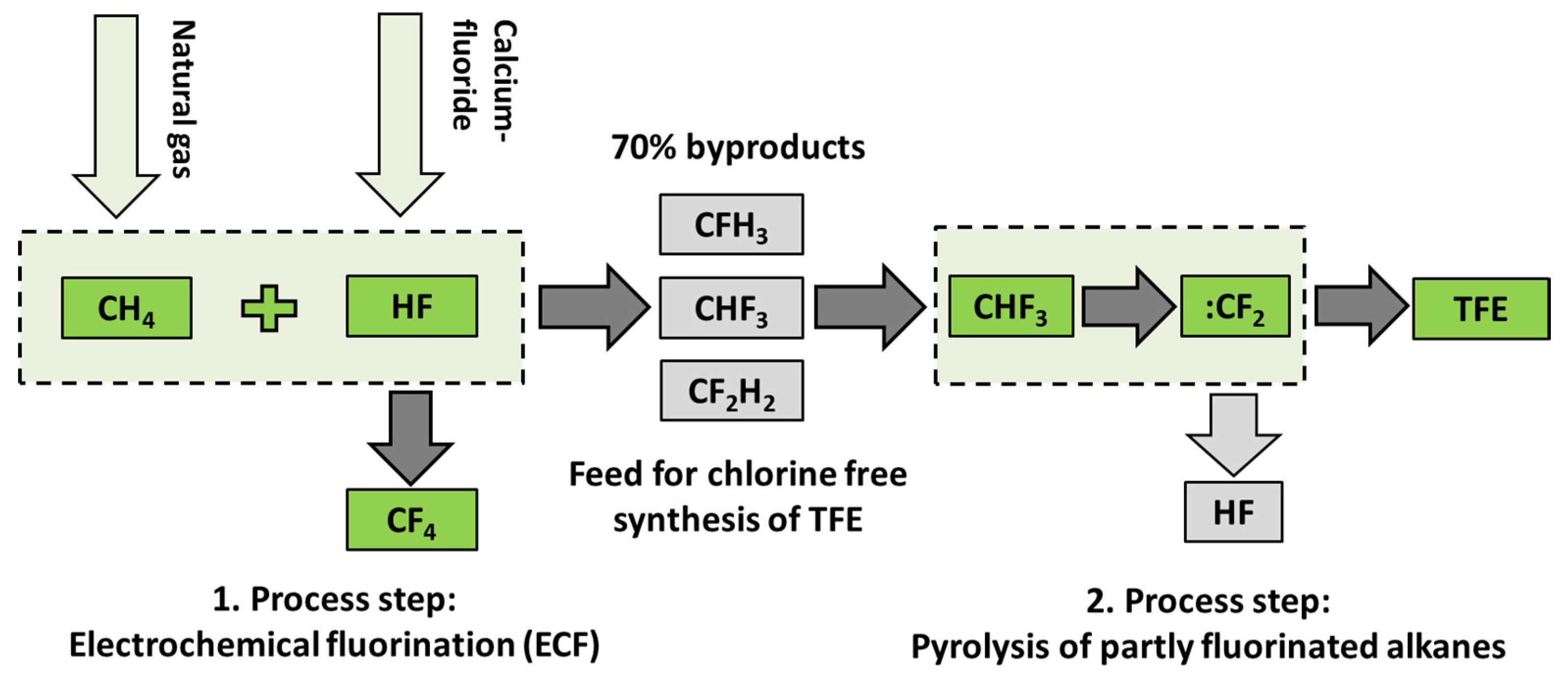
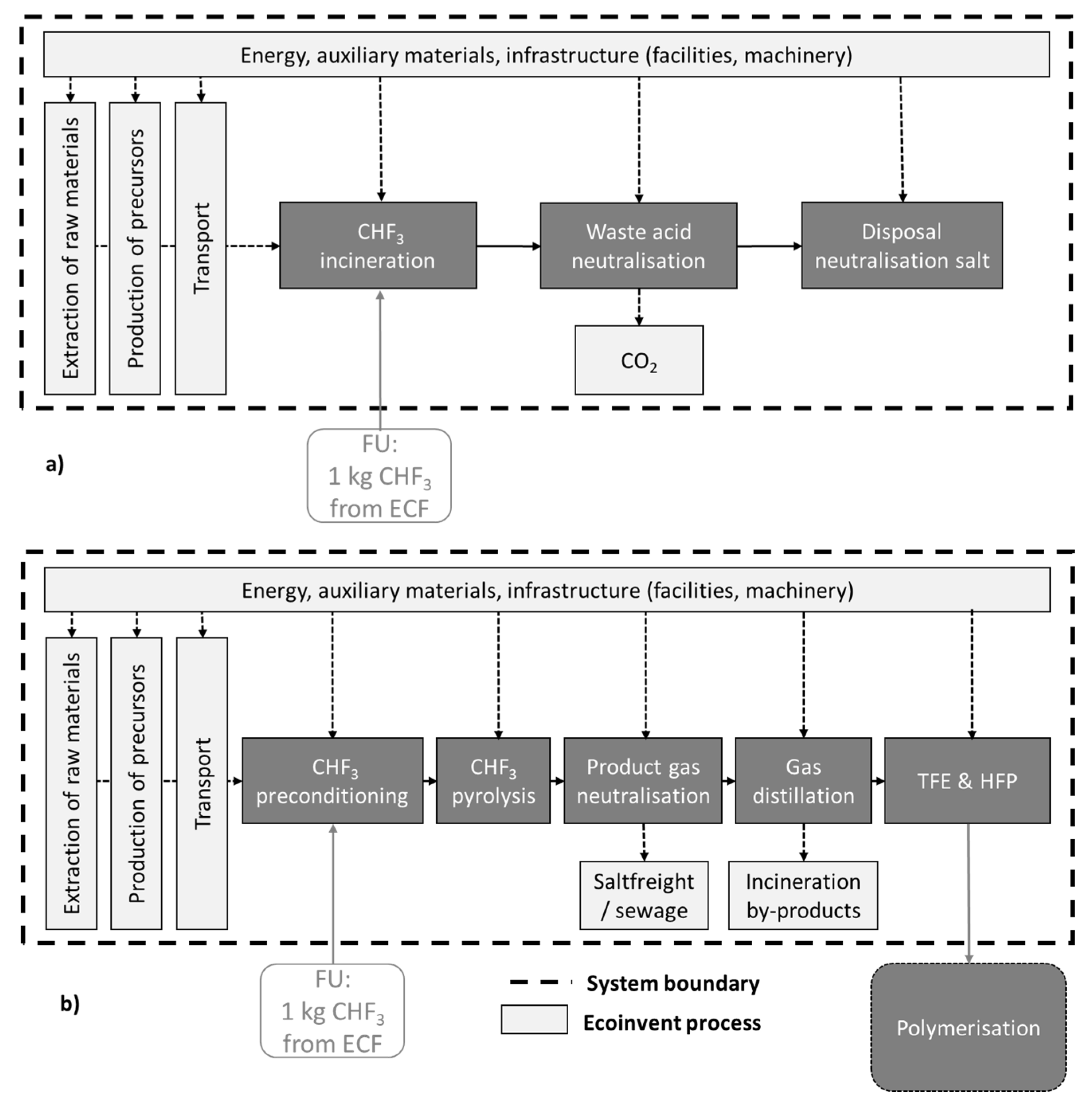
To counteract the disadvantages of thermal utilization and to utilize the complete product spectrum of the ECF, in this study, partly fluorinated alkanes were proven regarding their suitability as starting material for fluoromonomer production. The respective process route of a utilization of partly fluorinated compounds for the production of TFE and HFP is illustrated in Figure 1. The synthesis starts with the supply of feed gas as by-products of ECF followed by pyrolysis for generation of monomers like TFE and HFP. The main advantages of this process are the utilization of cheap starting materials (currently waste streams) and the prevention of HCl waste acids.
In the field of fluorine chemistry and fluorine materials, the handling and processing of different reactions in microreactors are of growing relevance. The reasons for this trend are safer handling of hazardous reactants, a reduction in the (potential) exposure to toxic or hazardous chemical species, and higher process safety in terms of thermal runaway by efficient cooling. Moreover, the application of microreactors in fluorine containing reactions is beneficial in terms of reduced reaction volume, optimal process conditions, and thus higher yields of target products [19,20]. Scale-up of a microreactor process can be easily done just by numbering up [21]. Microreactors are also advantageous with regard to kinetic studies of highly exothermic or endothermic reactions, for example, here for the highly endothermic decomposition of fluorinated hydrocarbons. Compared with lab-scale fixed bed reactors, microreactors have a much higher surface-to-volume ratio, which enables very efficient heating or cooling, and thus almost isothermal operation. Hence, the determination of kinetic parameters is not hindered by limitations of heat and mass transfer [22].
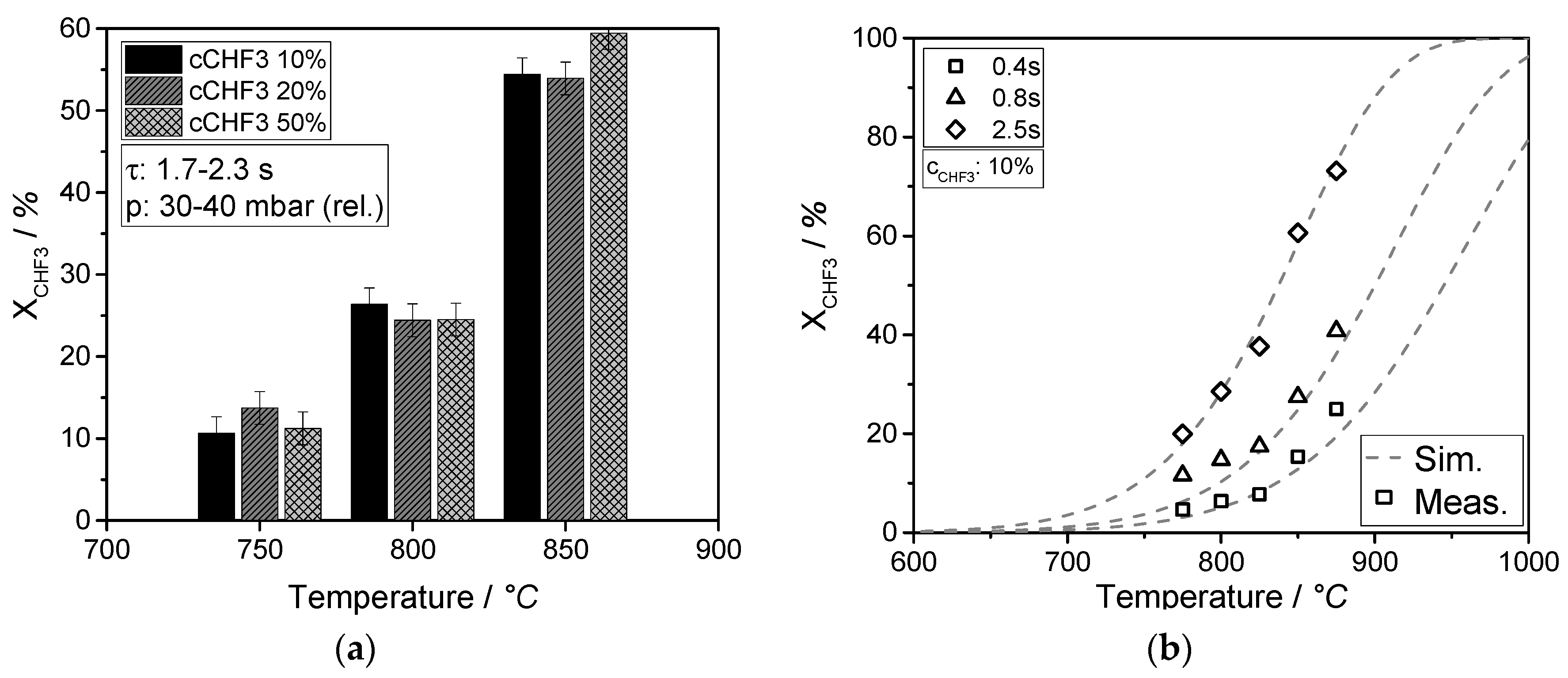
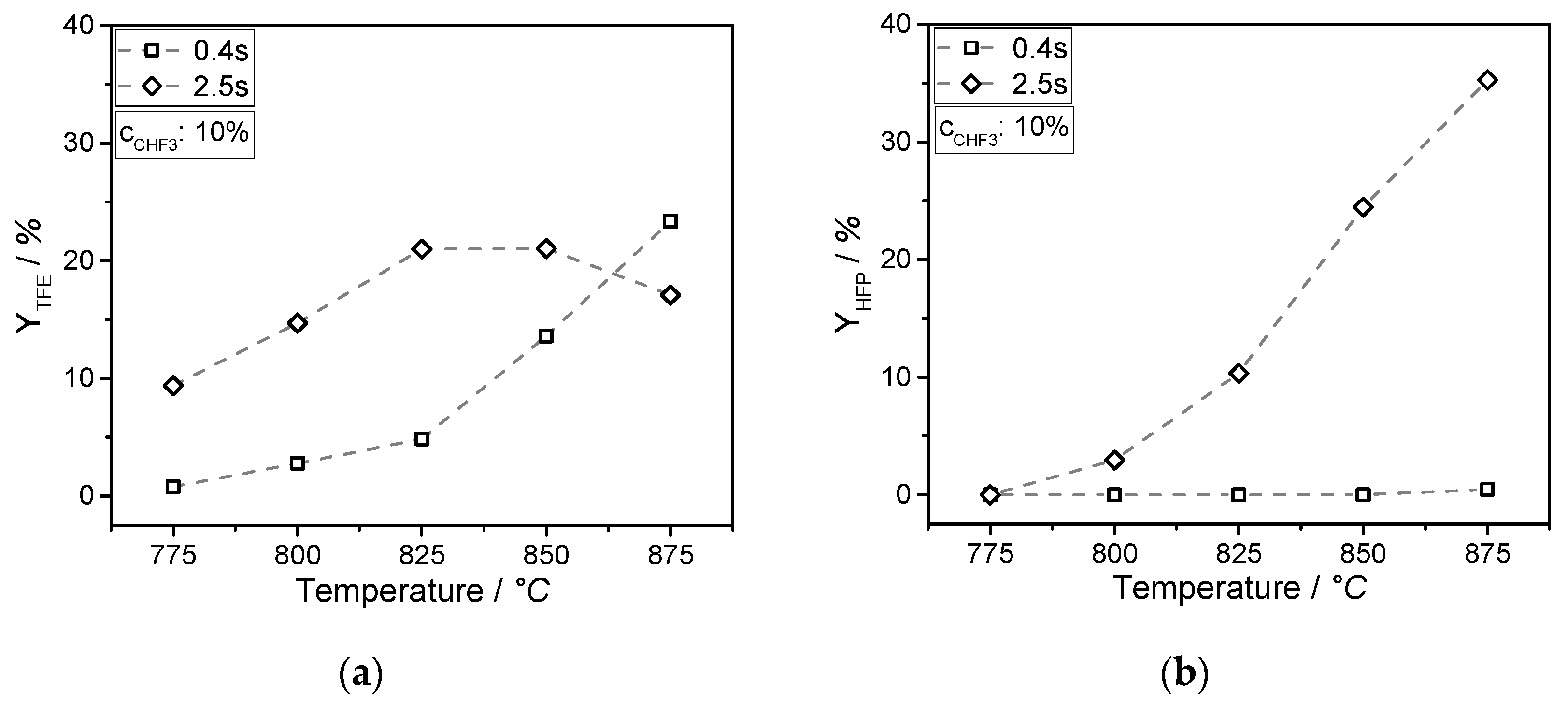
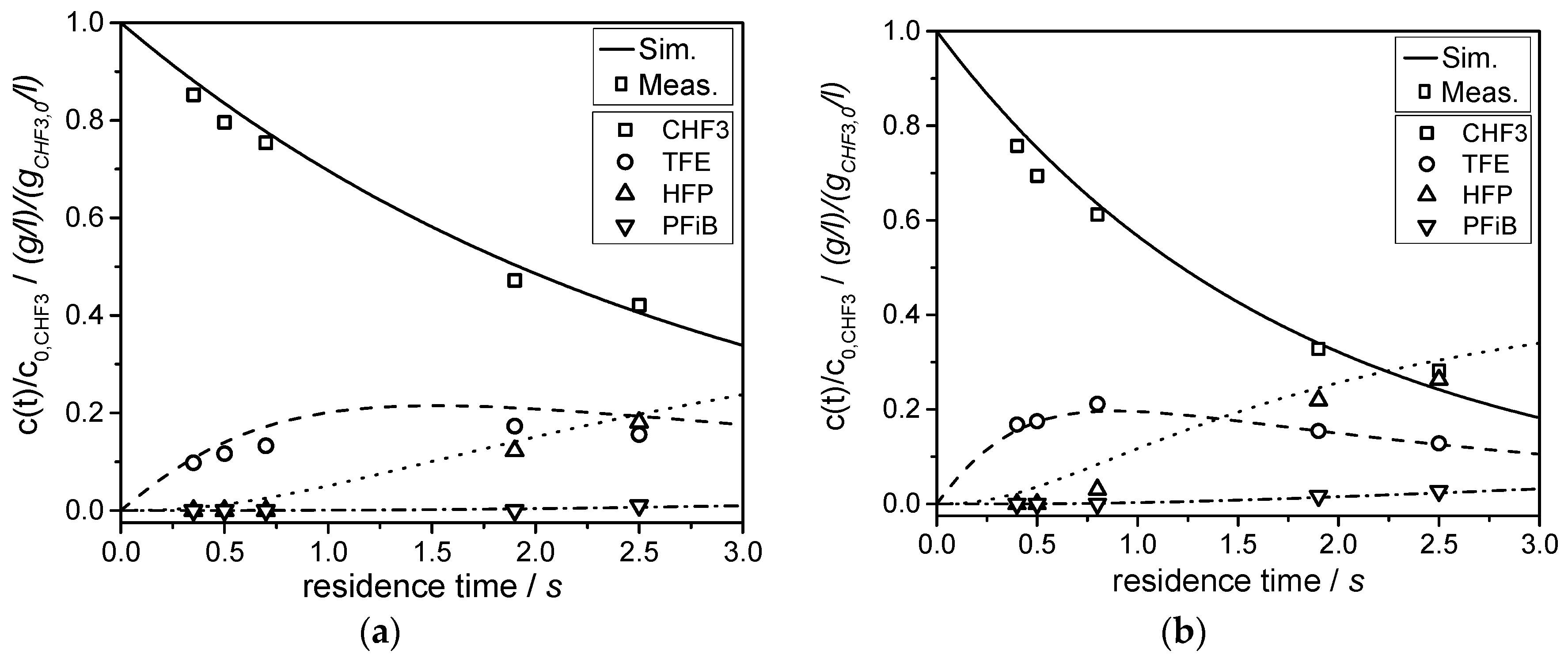
In this work, the experimental results of the pyrolysis of partly fluorinated alkane CHF3 in a high temperature microreactor are presented. On the basis of the rate of CHF3 conversion, the kinetic data of this initial reaction step of pyrolysis (dehydrofluorination of CHF3 to HF and difluorocarbene) were determined. In consecutive reactions, fluorinated products such as tetrafluoroethylene (TFE), hexafluoroproplene (HFP), and perfluoroisobutene (PFiB) are formed. The measured product distribution was compared with a simulation of the pyrolysis using kinetic data from literature for these consecutive steps. The optimum reaction conditions for monomer formation were investigated. Finally, the ecological and economical potential of the process was evaluated by a life cycle assessment (LCA).

2. Materials and Methods

2.1. Design of the Microreactor for the Pyrolsis of CHF3

Pyrolysis of partly fluorinated alkanes for the production of fluoromonomers and determination of kinetic parameters was carried out in a high temperature siliconcarbide (SiC) microreactor provided by 3M technical ceramics (Table 4).
The ceramic microreactor is depicted in Figure 2 and has a channel cross section of 1 mm2 and a reaction volume of 1.2 mL. The microreactor design consists of four sections. An in- and outlet for the supplied and produced gases, a meander reaction zone, and a quenching zone. The microreactor has beneficial material properties like high thermal conductivity and specific heat, which provides almost isothermal operation, and thus an accurate measurement of the kinetics of CHF3 pyrolysis and of the subsequent fluoromonomer formation, respectively.

2.2. Measurement Setup for Pyrolsis of CHF3

The setup for the determination of conversion of partly fluorinated substances is schematically depicted in Figure 3. It consisted of the gas supply, the high temperature micro reactor, the quenching with a following exhaust gas treatment, and the online gas chromatography (GC) analysis.
CHF3 was supplied by Air Liquide with purities of 99.95% and N2 by Sauerstoffwerke Friedrichshafen GmbH with purities of 99.9%. Mass flow controllers from Bronkhorst (EL-FLOW F-201CV) delivered the gases. The volumetric flow rate of fluoroform was varied from 0.25 to 5 mL min−1. N2 was used as inert carrier gas to adjust a volumetric content of 10% fluoroform in the feed stream. The microreactor was placed in a tubular electric furnace and heated to the desired constant temperature. The reaction temperature was monitored by one thermocouple placed in the meander shaped reaction zone (see Figure 2). After passing through the microreactor, the product gas was quickly quenched below 100 °C to avoid consecutive reactions of TFE to di- or other oligomers. Additionally, hydrogen fluoride (HF) formed through the pyrolysis was neutralized with KOH (40 g/L) during passage through a washing bottle. The HF-concentrations were determined by pH probe, Knick SE555X/1-NMSN, placed in the washing bottles. The moisture behind the washing column was removed via molecular sieve of 0.3 nm (Metrohm Ion analysis). For the detection of the product gas distribution, an online gas chromatography (GC) HP 6890 equipped with a thermal conductivity detector (TCD) and a Carbopack C33 column (6 m, 5% picric acid) was used. The GC was operated in the temperature range from 40 to 110 °C, with a temperature ramp of 10 K/min and a dwell time of 5 min at 110 °C. The detector ran at a temperature of 200 °C and the injection temperature was 150 °C.

2.3. Pyrolysis Reaction, Kinetic Modeling, and Life Cycle Assessment (LCA) for the Pyrolsis of CHF3

Experimental procedure: Before each pyrolysis experiment, the microreactor was purged with N2. The microreactor was then heated to the desired reaction temperature under N2 atmosphere. After reaching the target temperature, CHF3 was supplied. The pyrolysis experiments were conducted at temperatures of 775–875 °C, residence times of 0.4–2.5 s, a molar ratio of CHF3 to N2 of 0.1, and at almost atmospheric pressure (Table 5).
Modelling of CHF3 pyrolysis: Several researchers have already investigated the thermal decomposition of fluoroform (CHF3) over a broad temperature and residence time range, as well as with shockwave techniques or turbulent reactors. The main products in the pyrolysis of CHF3 reported in literature are the valuable monomers TFE and HFP, but also undesired partly fluorinated alkanes and alkenes like C2F6, C2HF3, C3F8, and C2F5H, as well as toxic compounds like i-C4F8 and HF [23]. It is generally agreed that the initial step in the synthesis of fluoromonomers is the highly endothermic decomposition of fluoroform yielding difluorocarbene (:CF2) [24]. Hence, an efficient supply of heat is needed to keep the dehydrofluorination going. The decomposition of CHF3 starts up at 700 °C and is intensified by an increase of temperature and residence time. Reported activation energies for the decomposition of CHF3 are in the range of 244–295 kJ/mol [24,25]. By dimerization of the generated difluorocarbene, the main product TFE is formed, but dimerization of difluorocarbene is reversible under reaction conditions, which is experimentally evidenced by Couture et al. [26] in their studies to produce HFP out of TFE. The yield of TFE passes a maximum value at a certain reaction (residence) time in consequence of the consecutive reaction with difluorocarbene to HFP [27]. Thus, the formation of fluoromonomers by pyrolysis of fluoroform depends on the generation and consumption of difluorocarbene. The complete reaction network of CHF3 pyrolysis, which consists of seven reactions, is described in detail in Section 3.3.
In this study, the calculation of the CHF3 conversion was done based on the kinetic parameters (pre-exponential factor, activation energy) determined by respective own experiments. The rates of formation of the consecutive products tetrafluoroethylene (TFE), hexafluoropropylene (HFP), and perfluoroisobutene (PFiB) were calculated based on the respective kinetic parameters reported in the literature. The differential equations describing both the CHF3 conversion and the product yields at different residence times and temperatures were solved by Matlab R2015b using ode 45 solver.
Life cycle analysis (LCA): The evaluation of the ecological and economical potential of the developed process (LCA) was carried out according to ISO 1404X standards with the software Simapro 8.3.0 and the Database ecoinvent 3.3. The assessment criteria are the cumulative energy demand (CED) in version V1.09 and the 18 impact categories of the ReCiPe method midpoint (H) v1.12/European ReCiPe (H).

3. Results

3.1. Calculation of Conversion and Yield in the Pyrolysis of CHF3

The pyrolysis of CHF3 can be regarded as a first order reaction:
r C H F 3 = d c C H F 3 d τ = k C H F 3 c C H F 3 .
The reaction rate r (mol m−3 s−1) is defined here based on the residence time (τ) in the tubular reactor and depends on the rate constant kCHF3 (1/s) and the concentration of CHF3 (mol m−3). For an isothermal and ideal plug flow reactor, integration of Equation (11) yields the following conversion:
X C H F 3 = 1 e k C H F 3 τ .
The assumption of a plug flow reactor is only valid in good approximation for a highly turbulent flow (Reynolds number Re > 2300). For the microreactor used in this study, Re is defined as
R e = u   d h y d ν ,
where u is the gas velocity (at reaction conditions), dhyd is the characteristic (hydraulic) diameter, and ν is the kinematic viscosity. For a quadratic channel with height and width s (both here 1 mm), dhyd is given by the following (A: cross sectional area; C: circumference):
d h y d = 4 · A C = 4   s 2 4   s = s .
For the given microreactor, Re is very small, for example, 23 for a typical residence time of 0.4 s and temperature of 875 °C. Thus, the flow is strictly laminar under the applied conditions in this study.
For laminar flow, the conversion of CHF3 in a tubular reactor is usually calculated as follows [28]:
X l a m = 1 ( 1 D a 2 ) · e D a 2 D a 2 4 D a 2 e x x d x ,
D a = k C H F 3 ( T ) · τ ,
k C H F 3 ( T ) = k C H F 3 , 0 e E A R T ,
τ = V r e a c t o r V ˙ F e e d ( T ) = L r e a c t i o n   z o n e u F e e d ( T ) .
Da is the so-called Damköhler number. Solutions of the integral in Equation (15) are tabulated [29,30].
In the case of laminar flow, the assumption of plug flow behavior is not valid and usually a lower conversion (as determined by Equation (15)) is achieved compared with an ideal plug flow reactor (PFR) (Equation (12)). However, the advantage of the small dimensions (above all the small diameter) of the used microreactor is a relatively fast diffusion in the radial direction, that is, the characteristic time for radial diffusion, τD, is much shorter than the average residence time (τ) [28]. In Equation (19), rt is the radius of reaction channel, and Dmol is the diffusivity of gas (N2).
τ D = r t 2 D m o l τ = L r e a c t i o n   z o n e u F e e d ( T ) .
In this study, the residence time τ (0.4–2.5 s) is always higher than the characteristic time of diffusion τD (0.1 s, determined by Equation (19)). In this case, we may use the axially dispersed plug flow model and the so-called axial dispersion coefficient Dax, respectively, to inspect the deviation from an ideal PFR (see, for example, the work of [28]):
D a x u L t = 1 B o = D a x u d t d t L t ,
D a x = D m o l + u 2 d t 2 192 D m o l .
In the Equations (20) and (21), u is the gas velocity, and dt and Lt are the diameter and length of the reactor, respectively. The Bodenstein number Bo represents the ratio of convective flux to diffusive flux [28]:
B o = u L t D a x .
For Re higher than 10, the first term on the right-hand side of Equation (21) (Dmol) can be neglected and the Bo as a measure for the deviation from plug flow behavior reads as follows:
B o = 192 ( L t u ) ( D m o l 4 r t 2 ) = 192 τ 1 4 τ D 50 τ τ D    ( f o r   R e > 10 ) .
In general, plug flow is almost reached if Bo > 80 [28]. In the used microreactor, Bo is always >175 (875 °C, 0.4 s). Thus, Equation (12) is valid and was used to calculate the conversion of CHF3.
The yields and selectivities of TFE and HFP are calculated by the residual molar rates in mol/s (reactor outlet) and the initial molar rate of CHF3 (Equations (24)–(27)). The factors 2 and 3 consider the stoichiometry of the respective reactions.
Y T F E = 2 n ˙ T F E n ˙ C H F 3 , 0 ,
Y H F P = 3 n ˙ H F B n ˙ C H F 3 , 0 ,
S T F E = 2 n ˙ T F E n ˙ C H F 3 , 0 n ˙ C H F 3 = Y T F E X C H F 3 ,
S H F P = 3 n ˙ H F B n ˙ C H F 3 , 0 n ˙ C H F 3 = Y H F P X C H F 3 .
For the first order assumption, the rate constant is given (based on Equation (12)) by the following:
k C H F 3 = ln ( 1 X C H F 3 τ ) .
The pre-exponential factor k0 and the activation energy EA were determined by the Arrhenius equation (Equation (29) and the respective plot based on experiments at different temperatures (775 to 875 °C) and residence times (0.35 to 2.5 s). All experiments were conducted at atmospheric pressure.
ln ( k C H F 3 ) = ln ( k C H F 3 , 0 ) E A R 1 T .

3.2. Kinetic Parameters, Conversion, and Product Distribution in the Pyrolysis of CHF3

Kinetic parameters: The experimental data are fitted with a least square fitting for the calculation of the kinetic parameters. The data are shown in Figure 4a and the straight lines are in good agreement with the first order approach. The values of kCHF3,0 and EA are listed in Figure 4b.
First order assumptionand conversion: The measured CHF3 conversion for different concentrations of fluoroform is shown in Figure 5a for three temperatures. The conversion is constant for each temperature, which is a clear indication of a first order reaction.
In Figure 5b, the conversion of CHF3 is shown as a function of temperature for different residence times. The calculated CHF3 conversion (dashed lines) matches the experimental data (dots) quite well (for the assumption of a first order reaction). Measured conversion of about 25% at 875 °C and 0.4 s is in good agreement with CHF3 conversion of 27.3% in the experiments of Hauptschein et al. [12].
Product distribution: The products of CHF3 pyrolysis are practically only C2F4 and C3F6. C2F6 and i-C4F8 are only formed in traces at the highest measured temperatures. The yields and selectivities of TFE and HFP (as valuable products) at shortest and longest adjusted residence time are shown in Figure 6 and Figure 7 in a temperature range of 775 to 875 °C. With increasing temperature and residence time, the yield and selectivity, respectively, of the consecutive product HFP (C3F6) increases. In this study, a maximum yield of 23% TFE (0.4 s at 875 °C) and of 17% TFE and 35% HFP (2.5 s at 875 °C) is achieved. Compared with yields of Hauptschein et al. [12], the generated yields of TFE and HFP are in the same range. Thus, with the same process parameters (880 °C and 0.4 s), the calculated yield by Equations (24) and (25) of Hauptschein et al. is 17.9% for TFE and 6.6% for HFP. The highest yield of 58.1% is reached at 960 °C and 0.3 s. The maximum yield of fluoromonomers (52%) is obtained in this study at lower temperatures (about 100 °C) and longer residence times (2.5 s), which could be explained by the reversible dimerization of TFE to difluorocarbene and the consecutive reaction to HFP at the adjusted residence times [26].
Long-term process stability of CHF3-pyrolysis in the SiC-microreactor: After the evaluation of suitable process parameters, the CHF3 pyrolysis was carried out at residence times of 0.4 and 2.5 s for several hours to study the “long-term” microreactor stability and performance. Figure 8 shows that isothermal conditions and a stable reactor operation were reached in both cases after about 1 h. The time of 1 h is necessary for heating the oven to target temperatures and purging all tubes and washing bottles with the same concentration of reaction products.

3.3. Simulation of Product Distribution

The gas phase pyrolysis of CHF3 at temperatures between 775 and 875 °C was examined in more detail using both experimental data and modeling techniques. The first step in the pyrolysis of CHF3 is dehydrofluorination to hydrogen fluoride (HF) and difluorocarbene (:CF2); see Equation (8) [24,31,32]. Similar to the reaction of R22, the generated difluorocarbene dimerizes immediately to TFE [33]. The formation of HFP—Equation (10)—takes place by consecutive reaction of TFE with another CF2 carbene. The overall reaction network can be described by a series of consecutive reactions listed in Table 6. The kinetic parameters for CHF3 decomposition were experimentally determined in this study. For the remaining consecutive reactions, literature references were used (Table 6).
The kinetic parameters of the reaction of C2F4 (TFE) with a difluorocarbene radical (CF2) to C3F6 (HFP) were calculated by fitting k4(T) for each temperature and by the Arrhenius plot. Compared with the study of Ainagos [34], EA is in the same range, but k0 is lower (values in Table 6). The reaction network was then finally simulated with the kinetic parameters listed in Table 6. The comparison of experimental and simulated data is shown in Figure 9 for constant pyrolysis temperatures of 850 °C and 875 °C and a residence time up to 3 s. The measured and simulated (dimensionless) concentrations of the educt CHF3 and the products TFE, HFP, and PFiB are in good agreement.

3.4. Life Cycle Assessment (LCA)

Environmental protection and resource efficiency gain increasing importance in politics and economics as a result of changing legislative frameworks or a shortage of raw materials. In addition, the transition to renewable energy resources has far reaching effects on the available energy mix for an industrial process. Under economic and environmental aspects like the Paris international climate agreement, new processes need to be more cost- and resource-efficient. Thus, the energetic evaluation of production processes has become an important part in process development in the last two decades. One possibility to evaluate a process regarding required energies, their ecological damage potential, and waste disposal is the life cycle assessment (LCA). Implementation of an LCA enables the direct comparison of different process routes and the identification of savings potential with regard to energy and raw materials [38].
In this work, a comparative LCA of the proposed new chlorine-free pyrolysis process and the incineration process of fluoroform, which is the actual state of the art for handling partly fluorinated compounds, was done. In addition, the current industrial R22 route to produce fluoromonomers was used for evaluating the savings potential of this new process route.
To compare these three processes, we started by analyzing the single process steps of the different process routes and set the system boundaries. Afterwards, the calculation of mass and material flows and the thermal and electric process energies took place on the basis of thermodynamic and reaction requirements. For a better comparability between the industrial R22 route and our lab scale process, a scale up for the handling of 300 tCHF3/a was conducted. Evaluation criteria were the cumulative energy demand (CED) and the ReCiPe in different impact categories, like climate change, human toxicity, ozone depletion, and resource depletion.

3.4.1. Functional Unit, System Boundaries, Material Flow, and Process Energy

Our work compares the incineration of partly fluorinated alkanes (s. Table 1) with the newly developed process for recycling compounds originating from ECF (s. Table 2) and the R22 route (s. Table 2).
The first step contains the comparison of the incineration and pyrolysis of 1 kg of CHF3, which is defined as the functional unit (FU) in this work (Equation (30)).
FU = 1 kg CHF3.
Afterwards, the amount of generated fluoromonomers (TFE and HFP), which is obtained by the pyrolysis of 1 kg CHF3 (CHF3 route), is compared in a second step with the similar amount of fluoromonomer generated by the industrial R22 route.
In all cases, only the production of the fluoromonomers (TFE, HFP) was considered, in order to simplify the researched process chains. All subsequent products, for example, fluoropolymers, that are generated by polymerization are neglected because the energy costs for their production and disposal are similar. The defined system boundaries of the LCA for incineration and pyrolysis of 1 kg of CHF3 are shown in Figure 10. The CHF3 route in Figure 10 consists of the supply of the CHF3 from the ECF by train, the pyrolysis step at the optimum process parameters (875 °C, 2.5 s, CHF3 conversion 73%, and yield fluoromonomers 52%). This is followed by the exhaust gas treatment by quenching the product gas, neutralization of gaseous HF, and the following distillation of the generated monomers. The process of incineration of partly fluorinated compounds includes the CHF3 supply, the incineration step, and neutralization of the generated HF.
Additionally, the life cycle assessment is based on the following assumptions:
  • No energetic or ecological allocations for CHF3 (by-product of ECF);
  • No consideration of energetic and infrastructure processes for building the chemical plant, because of the theoretical scale up and its similarity to R22 pyrolysis;
  • The supplied energy consists of the usual energy mix in Germany (2014);
  • The energy demand for the CHF3 route is subjected to a conservative estimation, whereby a higher saving potential of the overall energy demand is possible.
The generated data for energy and mass flows in the CHF3 route and CHF3 incineration are obtained in this study or estimated in a scale up of the CHF3 pyrolysis process. The data for the balancing of incineration of partly fluorinated compounds originate from an exhaust gas incineration plant. In contrast to the newly developed process to produce fluoromonomers, the standard process of TFE production, R22 pyrolysis, is already stored in the ecoInvent-database. Table 7 shows the heat and material flows for each of the compared processes.

3.4.2. ReCiPe Impact Categories

The environmental influences of the evaluated processes, incineration, and pyrolysis of CHF3, are shown in Figure 11 for the selected impact category. Under environmental aspects, the incineration of the CHF3 is the best process for handling partly fluorinated ECF waste streams in all investigated impact categories. However, the incineration of CHF3 generates no fluoromonomers; a closer look must be taken at the two remaining processes for producing TFE and HFP.
Comparison of the monomer production processes in Figure 12 clarifies that the standard R22 route causes the highest environmental effects in every impact category. The R22 route performs the worst in the impact categories of climate change, ozone, and fossil depletion, as well as human toxicity. In contrast to the actual industrial process, the CHF3 route gets significantly better environmental results in every single impact category. The saving potential in the categories of climate change and fossil depletion is about a factor of two, a factor of 10 for human toxicity, and a factor of 10,000 for ozone depletion. The advantages of the CHF3 pyrolysis in terms of ozone depletion and climate change result mainly from the high global warming potential (GWP) of CHF3 [17]. Additionally, the developed process avoids undesirable by-products, for example, HF contaminated HCl, which improves the environmental performance even more.

3.4.3. Cumulative Energy Demand (CED)

The calculated CEDs of the compared processes are illustrated in Figure 13. Incineration of CHF3 has an energy demand of 28.3 MJ, while pyrolysis of CHF3 and the industrial R22 route consumes 45.1 MJ and 79.5 MJ, respectively. Under an energetic aspect, incineration of CHF3 is the best process to handle ECF waste stream, but at the end of the incineration, only CO2, high amounts of waste acids (HF), and no valuable product are generated. Compared with incineration, the CED of the CHF3 route in Figure 13a show that by increasing the amount of energy by about 40%, valuable monomers like TFE and HFP can be obtained out of a currently unused residue, which actually generates costs for its incineration and disposal.
High savings potential of the developed pyrolysis process is evidenced by comparison with the industrial R22 route in Figure 13b. Originating from the residual CHF3 from ECF, 40% energy savings are obtained to produce the same amount of fluoromonomers. The energy demand for the single pyrolysis step of CHF3 is higher than that in R22 pyrolysis because of the higher reaction temperature, but the previous process steps of chlorination from methane to R22 and the required auxiliaries like Cl2, Sb-catalysts, and HF can be replaced completely.
Besides the material utilization of partly fluorinated residues, a chlorine-free synthesis of TFE and HFP requires the targeted production of CHF3 via the ECF and the following pyrolysis of the generated CHF3. The calculated energy demand of this combined process compared to the industrial R22 route is shown in Figure 14. The synthesis of CHF3 and the following pyrolysis of a mixture of CHF3 (10%) and nitrogen (90%) has a nearly equal CED compared with the R22 route. Considering the assumption proved earlier of a first order reaction and the consequence of an independence of concentration in Figure 5a, the concentration of CHF3 in the educt stream is able to increase to 50% (Figure 5a) and an energy saving of more than 10% is achieved.
Additionally, chlorine chemistry is fully substituted. Furthermore, the entire energy consumption of the process can be reduced by implementing gas burners instead of electrical heating of the reactors, with the disadvantage of a higher GWP, and additionally increasing the amount of fluorocarbon against nitrogen. Nevertheless, the advantage of the presented process, the reduction of four process steps in the R22 route to a one-step synthesis using partly fluorinated residues or a maximum two-step process with a target production of CHF3 and a following pyrolysis, is obvious.

4. Discussion

Partly fluorinated compounds (such as CHF3) originate from electrochemical fluorination. In this study, the chlorine-free synthesis of tetrafluoroethylene and hexafluoropropylene by pyrolysis of CHF3 was studied. The pyrolysis was conducted in a microreactor at atmospheric pressure in a temperature range of 775 to 875 °C. Conversion of CHF3 turned out to be a first order reaction. The initial step of the gas phase pyrolysis of CHF3 is formation of HF and CF2 (difluorocarbene), which dimerizes immediately to C2F4. With prolonged residence time, C3F6 is obtained by the reaction of TFE and CF2. The activation energy (EA) and the pre-exponential factor (k0) of the decomposition of CHF3 to HF and CF2 were determined.
The formation of C2F4, C3F6, and i-C4F8 can be described by a reaction network consisting of six reactions. The simulation is in good agreement with the experimental data. The conversion of CHF3 reaches 73% at a temperature of 875 °C, and a yield of about 52% fluoromonomers is obtained. Short residence times and/or high temperatures, isothermal conditions, and quenching of the product gas to avoid consecutive reactions maximizes the yield of fluoromonomers. These conditions could be realized in the ceramic microreactor used in this study.
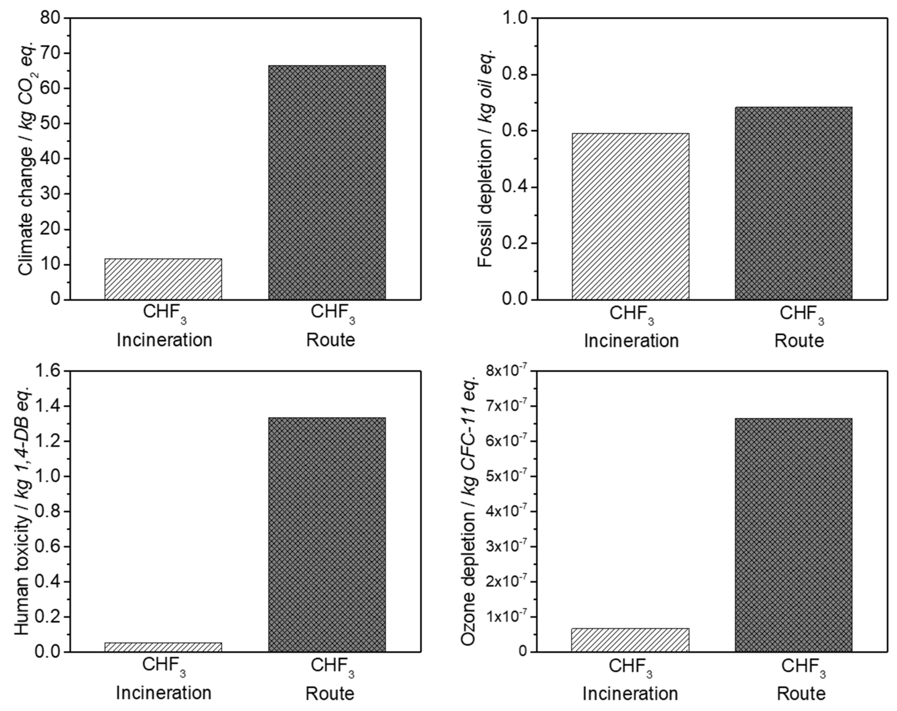
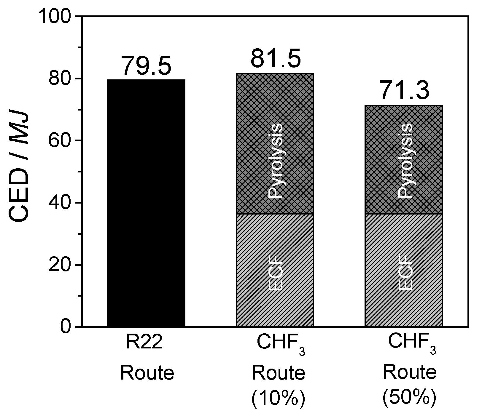
The life cycle assessment for the developed CHF3 route demonstrates the ecological and economic benefit of this process. It is shown that the material utilization of CHF3 is preferable to incineration. In contrast to the generation of high amounts of waste acids at CHF3 incineration, the material utilization of CHF3 requires a higher energy expenditure (40%), but generates high yields of the valuable products TFE and HFP. In comparison with the industrial R22 route, the developed CHF3 pyrolysis requires 40% less energy for the production of the same amount of fluoromonomers. Additionally, a reduction in terms of climate change and ozone depletion of 50% is obtained.
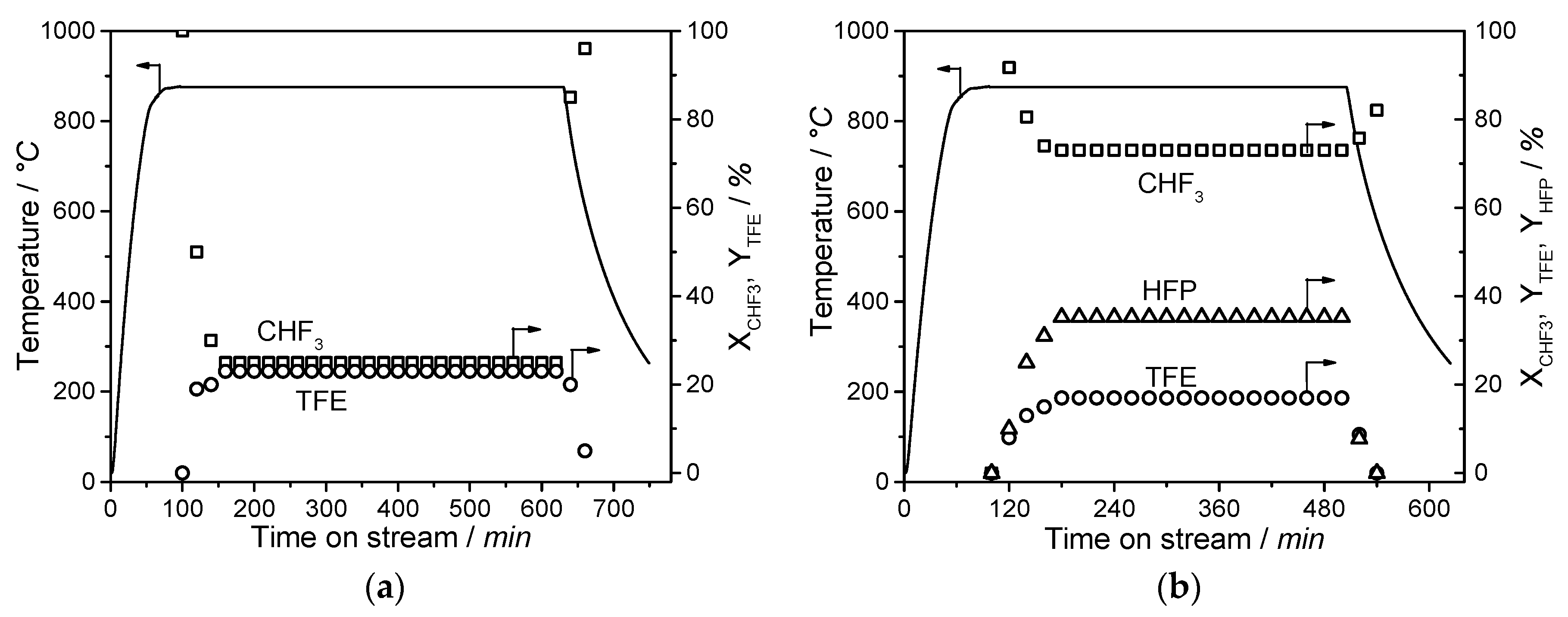
The developed process provides a sustainable synthesis of fluoromonomers with the material utilization of partly fluorinated compounds instead of their incineration. In this study, it is shown that the CHF3 pyrolysis process is stable with a time on stream of about 8 h, shows no significant corrosion on the developed microreactor, and is thus ready for an industrial application. A scale up of the process is possible by employing multiple micro reactors in parallel or by a conventional scale up inspired by the R22 route with a tube bundle reactor, which is adjusted to the higher temperatures. Beneficial for the scale up is the proven first order reaction, which simplifies the reaction engineering. With regard to the tremendous saving potential in energy consumption, undesirable by-products, disposing waste materials, and the complete substitution of chlorine chemistry, the developed process is suitable to be transferred into the industrial scale. Especially, the developed reactor enables the pyrolysis of partly and perfluorinated gases and, therefore, becomes a big step in a complete closing of the fluorine cycle.

Author Contributions

K.M. designed and performed the study and wrote the paper. A.S. helped in the design of the reactor sealing and in analyzing experimental as well as LCA data. T.G. was responsible for funding acquisition and A.J. supported the kinetic measurement and data evaluation. K.H. contributed the used gases and crosschecked the gas samples in the laboratories of 3 M.

Funding

Deutsche Bundesstiftung Umwelt (DBU) is gratefully acknowledged for financial support (reference number: 31819/01-31).

Acknowledgments

This publication was funded by the German Research Foundation (DFG) and the University of Bayreuth in the funding programme Open Access Publishing.

Conflicts of Interest

The authors declare no conflict of interest.

References

  1. Ebnesajjad, S. Fluoroplastics, Volume 1, Non-Melt Processible Fluoropolymers, 2nd ed.; William Andrew: Waltham, MA, USA, 2015; ISBN 9781455731992. [Google Scholar]
  2. Krämer, R. Social Megatrends Give Fluoropolymers a Boost. Kunstst. Int. 2016, 10, 82–86. [Google Scholar]
  3. Costa, C.M.; Silva, M.M.; Lanceros-Méndez, S. Battery separators based on vinylidene fluoride (VDF) polymers and copolymers for lithium ion battery applications. RSC Adv. 2013, 3, 11404. [Google Scholar] [CrossRef]
  4. Wang, H.; Sencadas, V.; Gao, G.; Gao, H.; Du, A.; Liu, H.; Guo, Z. Strong affinity of polysulfide intermediates to multi-functional binder for practical application in lithium–sulfur batteries. Nano Energy 2016, 26, 722–728. [Google Scholar] [CrossRef]
  5. Edwards, J.W.; Small, P.A. Kinetics of Pyrolysis of Chlorodifluoromethane. Ind. Eng. Chem. Fund. 1965, 4, 396–400. [Google Scholar] [CrossRef]
  6. Broyer, E.; Bekker, A.Y.; Ritter, A.B. Kinetics of the pyrolysis of chlorodifluoromethane. Ind. Eng. Chem. Res. 1988, 27, 208–211. [Google Scholar] [CrossRef]
  7. Downing, F.B.; Benning, A.F. Pyrolyses of Chloro-Fluro Alkanes. U.S. Patent US2551573, 8 May 1951. [Google Scholar]
  8. Chinoy, P.B.; Sunavala, P.D. Thermodynamics and kinetics for the manufacture of tetrafluoroethylene by the pyrolysis of chlorodifluoromethane. Ind. Eng. Chem. Res. 1987, 26, 1340–1344. [Google Scholar] [CrossRef]
  9. Bjornson, G. Plasma Jet Conversion of Fluoroform. U.S. Patent US3471546, 7 October 1969. [Google Scholar]
  10. Farlow, M.W. Process for Producing Tetrafluoroethylene from Perfluorocarbon Having At Least Three Carbon Atoms. U.S. Patent US2709182, 24 May 1955. [Google Scholar]
  11. Gelblum, P.G. Disposal of Fluoroform (HFC-23). U.S. Patent US6806396 B2, 19 October 2004. [Google Scholar]
  12. Hauptschein, M.; Fainberg, A.H. Production of Fluornated Compounds. U.S. Patent US3009966A, 21 November 1961. [Google Scholar]
  13. Bauer, G.L. Process for Manufacturing Fluoroolefins. U.S. Patent US6919015 B2, 22 July 2005. [Google Scholar]
  14. Aschauer, S.J.; Herdegen, J.; Schmidt, A.; Gerdes, T.; Hintzer, K.; Zipplies, T.; Willert-Porada, M. Kontinuierliches Verfahren zur chlorfreien Synthese von Tetrafluorethylen. Chem. Ing. Tech. 2014, 86, 529–537. [Google Scholar] [CrossRef]
  15. Schmeisser, M.; Sartori, P. Die elektrochemische Fluorierung. Chem. Ing. Tech. 1964, 36, 9–14. [Google Scholar] [CrossRef]
  16. Nagase, S.; Tanaka, K.; Baba, H. Direct Preparation of Partially Fluorinated Methane. BCSJ 1965, 38, 834–838. [Google Scholar] [CrossRef]
  17. Houghton, E. Climate Change 1995: The Science of Climate Change (IPCC); Cambridge University Press: Cambridge, UK, 1998; ISBN 0 521 56436 0. [Google Scholar]
  18. Nagase, S.; Tanaka, K.; Baba, H.; Abe, T. The Fluorination of Ethylene and Ethane. BCSJ 1966, 39, 219–222. [Google Scholar] [CrossRef] [Green Version]
  19. Sansotera, M.; Baggioli, A.; Ieffa, S.; Tedesco, M.; Sacchi, B.; Bianchi, C.L.; Navarrini, M.; Migliori, M.; Magagnin, L.; Navarrini, W. Catalytic microreactor with electrodeposited hierarchically nanostructured nickel coatings for gas-phase fluorination reactions. J. Fluor. Chem. 2018, 205, 22–29. [Google Scholar] [CrossRef]
  20. Gutmann, B.; Köckinger, M.; Glotz, G.; Ciaglia, T.; Slama, E.; Zadravec, M.; Pfanner, S.; Maier, M.C.; Gruber-Wölfler, H.; Oliver Kappe, C. Design and 3D printing of a stainless steel reactor for continuous difluoromethylations using fluoroform. React. Chem. Eng. 2017, 2, 919–927. [Google Scholar] [CrossRef] [Green Version]
  21. Kirschneck, D.; Marr, R. Anlagenkonzepte in der Mikroverfahrenstechnik. Chem. Ing. Tech. 2006, 78, 29–38. [Google Scholar] [CrossRef]
  22. Jähnisch, K.; Hessel, V.; Löwe, H.; Baerns, M. Chemistry in microstructured reactors. Angew. Chem. Int. Ed. Engl. 2004, 43, 406–446. [Google Scholar] [CrossRef] [PubMed]
  23. Zhang, P.; Cao, L.; Pan, R.; Jiang, Z.; Qin, K.; Li, Q. A Study on the Pyrolysis of CHF3. Procedia Eng. 2013, 62, 337–341. [Google Scholar] [CrossRef] [Green Version]
  24. Han, W.; Kennedy, E.M.; Kundu, S.K.; Mackie, J.C.; Adesina, A.A.; Dlugogorski, B.Z. Experimental and chemical kinetic study of the pyrolysis of trifluoroethane and the reaction of trifluoromethane with methane. J. Fluor. Chem. 2010, 131, 751–760. [Google Scholar] [CrossRef]
  25. Hidaka, Y.; Nakamura, T.; Kawano, H. High temperature pyrolysis of CF3H in shock waves. Chem. Phys. Lett. 1991, 187, 40–44. [Google Scholar] [CrossRef]
  26. Couture, M.J.; Gerner, H.M.B.; Gibbs, H.H. Process for Reducing the Formation of Process for Reducing the Formation of Polymer Attenedant the Pyrolyses of Tetrafluoroethylene. U.S. Patent US3578721A, 11 May 1968. [Google Scholar]
  27. Yu, H.; Kennedy, E.M.; Mackie, J.C.; Dlugogorski, B.Z. An Experimental and Kinetic Modeling Study of the Reaction of CHF 3 with Methane. Environ. Sci. Technol. 2006, 40, 5778–5785. [Google Scholar] [CrossRef]
  28. Jess, A.; Wasserscheid, P. Chemical Technology. An Integral Textbook; Wiley-VCH: Weinheim, Germany, 2013; ISBN 978-3-527-30446-2. [Google Scholar]
  29. Forst, W.; Hoffmann, D. Die Γ-Funktion. In Funktionentheorie erkunden mit Maple; Springer-Lehrbuch; Springer: Berlin/Heidelberg, Germany, 2012; pp. 281–298. [Google Scholar] [CrossRef]
  30. Watson, G.A. Numerical Analysis, Proceedings of the Dundee Conference on Numerical Analysis; Springer: Berlin, Germany, 1976; Volume 506. [Google Scholar] [CrossRef]
  31. Moon, D.J.; Chung, M.J.; Kim, H.; Kwon, Y.S.; Ahn, B.S. Pyrolysis of Trifluoromethane to Produce Hexafluoropropylene. Ind. Eng. Chem. Res. 2002, 41, 2895–2902. [Google Scholar] [CrossRef]
  32. Wang, G.; Yin, H.; Yuan, S.; Chen, Z. Studies on oligomerization and kinetic of pyrolyzing trifluoromethane to tetrafluoroethylene and hexafluoropropylene. J. Anal. Appl. Pyrolysis 2015, 116, 27–33. [Google Scholar] [CrossRef]
  33. Barnes, G.R.; Cox, R.A.; Simmons, R.F. The kinetics of the gas-phase thermal decomposition of chlorodifluoromethane. J. Chem. Soc. B 1971, 1176. [Google Scholar] [CrossRef]
  34. Ainagos, A.F. Mechanism and Kinetics of Pyrolysis of Perfluorohexane. Kinet. Catal. 1991, 32, 720–725. [Google Scholar]
  35. Poltanskii, S.F.; Shevchuk, V.U. Thermal conversion of fluoromethane I. Kinet. Katal. 1968, 9, 496. [Google Scholar]
  36. Poutsma, M.L. Chain elongation during thermolysis of tetrafluoroethylene and hexafluoropropylene: Modeling of mechanistic hypotheses and elucidation of data needs. J. Anal. Appl. Pyrolysis 2011, 92, 25–42. [Google Scholar] [CrossRef]
  37. Bauer, S.H.; Javanovic, S. The pyrolysis of octafluorocyclobutane—Revisited. Int. J. Chem. Kinet. 1998, 30, 171–177. [Google Scholar] [CrossRef]
  38. Frischknecht, R.; Jungbluth, N.; Althaus, H.-J.; Bauer, C.; Doka, G.; Dones, R.; Hischier, R. Implementation of Life Cycle Impact Assessment Methods: Ecoinvent Report No. 3. v2.0. Available online: Esu-services.ch/fileadmin/download/publicLCI/03_LCIA-Implementation.pdf (accessed on 20 June 2019).
Figure 1. Design of a two-step chlorine-free process for fluoromonomer production.
Chemengineering 03 00077 g001
Figure 2. Microreactor used for the experiments: (1) gas inlet, (2) reaction zone, (3) thermocouple guide tube, (4) quenching system, and (5) product gas outlet.
Chemengineering 03 00077 g002
Figure 3. Flow sheet of the measurement setup for the pyrolysis of partly fluorinated alkanes.
Chemengineering 03 00077 g003
Figure 4. Measurement of kinetic parameters in the pyrolysis of CHF3: (a) determination of k(T) at different temperatures, (b) Arrhenius plot for determination of EA and kCHF3,0.
Chemengineering 03 00077 g004
Figure 5. (a) Conversion of CHF3 for different temperatures and (b) comparison of simulated and measured conversion of CHF3 over temperature for different residence times.
Chemengineering 03 00077 g005
Figure 6. Measured product formation in the pyrolysis of CHF3: (a) yield of C2F4 and (b) yield of C3F6 (line: guide for the eye, dot: experimental data).
Chemengineering 03 00077 g006
Figure 7. Selectivity of fluoromonomers TFE (a) and HFP (b) in the pyrolysis of CHF3 (line: guide for the eye, dot: experimental data).
Chemengineering 03 00077 g007
Figure 8. Time on stream: (a) production of C2F4 (0.4 s) and (b) production of C2F4 and C3F6 (2.5 s) at 875 °C.
Chemengineering 03 00077 g008
Figure 9. Simulation of CHF3 pyrolysis: (a) 850 °C and (b) 875 °C.
Chemengineering 03 00077 g009
Figure 10. System boundaries for (a) incineration of CHF3 and (b) chlorine-free synthesis of TFE and HFP by pyrolysis of CHF3. ECF, electrochemical fluorination.
Chemengineering 03 00077 g010
Figure 11. Selected categories with highest impact factors in the comparison of incineration and pyrolysis of CHF3.
Chemengineering 03 00077 g011
Figure 12. Selected categories with the highest impact factors in the comparison of monomer production processes R22 and CHF3 pyrolysis.
Chemengineering 03 00077 g012
Figure 13. (a) Cumulative energy demand (CED) of the compared processes and (b) comparison of new developed chlorine-free against standard monomer production.
Chemengineering 03 00077 g013
Figure 14. Comparison of the cumulative energy demand of new developed chlorine-free against standard monomer production.
Chemengineering 03 00077 g014
Table 1. Reaction equations of the industrial R22 route.
ReactionrH298 [kJ/mol]Equation
C H 4 + 3   C l 2   450 ° C     C H C l 3 + 3   H C l −305Equation (1)
C H C l 3 + 2   H F   S b C l 5   C H C l F 2 + 2   H C l 168Equation (2)
C H C l F 2   800 ° C   : C F 2 + H C l 120Equation (3)
2   : C F 2   800 ° C   C 2 F 4 −295Equation (4)
Table 3. Reaction equation of incineration and pyrolysis of CHF3.
ReactionEquation
CHF3 incineration C H F 3 + 1 2   O 2   3   H F + C O 2 Equation (5)
C H 4 + 2   O 2   2   H 2 O + C O 2 Equation (6)
C a ( O H ) 2 + 2   H F   2   H 2 O + C a F 2 Equation (7)
CHF3 pyrolysis C H F 3   H F + : C F 2 Equation (8)
2   : C F 2   C 2 F 4 Equation (9)
C 2 F 4 +   : C F 2   C 3 F 6 Equation (10)
Table 4. Technical data of SiC-microreactor.
Material PropertiesUnitValue
Densityg/cm3>3.15
Porosity%<2.0
Grain sizeµm2–10
Thermal conductivity λSiC at 25 °CW/(m K)130
Specific heat cSiC at 25 °CJ/(g K)0.69
Table 5. Experimental parameters of CHF3 pyrolysis.
ParametersUnitRange
Temperature°C775–875
Pressurembar1013–1263 (absolute)
Flow rate (standard temperature and pressure (STP))mL/min7.5–50
Residence time s0.4–2.5
Table 6. Kinetic parameters of the consecutive reaction network.
Reactionkn (T)k0 [s−1 or s−1M−1]EA [kJ/mol]Literature
C H F 3   H F + : C F 2 k14.16 × 108195this study
2   : C F 2   C 2 F 4   ( T F E ) k28.71 × 1080Poltanskii [35]
C 2 F 4     2   : C F 2 k34.57 × 1016293Poltanskii [35]
C 2 F 4 +   : C F 2   C 3 F 6   ( H F P ) k44.97 × 108122this study (calc. from data)
C 3 F 6   C 2 F 4   +   : C F 2   k51.91 × 1013333Poutsma. [36]
C 3 F 6 +   : C F 2     i C 4 F 8   ( P F i B ) k61.20 × 1016385Bauer [37]
Table 7. Mass balances and process energies for the incineration and pyrolysis of 1 kg of CHF3.
CHF3 RouteCHF3 IncinerationECF
TransportPyrolysisNeutralizationDistillation HFECF
Freight traintkm/kg0.9
natural gaskg/kg 0 2.60
ElectricitykWh/kg 1.50.320.21 0.691.22
CHF3kg/kg1 0.31 1
CH4m3/kg 0.33
airkg/kg 0 50.65
H2Okg/kg 0 5.60
CO2kg/kg 0 7.79
HFkg/kg 0.2 0.8610.85
NaOH (18%)kg/kg 3.17 9.49
Salt sewage (NaF)kg/kg 0.6 1.80
Waste waterkg/kg 3.4 43.2
N2kg/kg 3.69 0
TFE/HFPkg/kg 0.540
CaF2kg/kg 2
H2SO4kg/kg 2.5

