Article

KLa Determination Using the Effectiveness-NTU Method: Application to Countercurrent Absorbers in Operation Using Viscous Solvents for VOCs Mass Transfer

IMT Atlantique, GEPEA, UMR CNRS 6144, F-44307 Nantes CEDEX, France
ChemEngineering 2019, 3(2), 57; https://doi.org/10.3390/chemengineering3020057
Submission received: 4 February 2019 / Revised: 1 March 2019 / Accepted: 24 May 2019 / Published: 1 June 2019

Abstract

:
In this study, the Effectiveness-NTU method, which is usually applied to heat exchanger design, was adapted to gas–liquid countercurrent absorbers to determine the overall mass transfer coefficient, KLa, of the apparatus in operation. It was demonstrated that the ε-NTU method could be used to determine the KLa using the Henry coefficient of the solute to be transferred (HVOC), the gas flow-rate (QG), the liquid flow-rate (QL), the scrubber volume (V), and the effectiveness of the absorber (ε). These measures are calculated from the gaseous concentrations of the solute measured at the absorber inlet (CGin) and outlet (CGout), respectively. The ε-NTU method was validated from literature dedicated to the absorption of volatile organic compounds (VOCs) by heavy solvents. Therefore, this method could be a simple, robust, and reliable tool for the KLa determination of gas–liquid contactors in operation, despite the type of liquid used, i.e., water or viscous solvents.

1. Introduction

The removal of volatile organic compounds (VOCs) from the air can be achieved using gas–liquid reactors. However, some VOCs are poorly soluble in water leading to mass transfer limitations. In response to the low solubility of hydrophobic pollutants, water can be replaced by heavy viscous organic solvents (silicone oils, alkanes, phthalates, [1]) to improve the mass transfer [2]. Basically, the absorption step is crucial, since VOCs have to be solubilized for further treatments. Usually, the mass transfer between the gas phase and the liquid phase (water) is performed in countercurrent gas–liquid packed absorbers, where the design procedure is clearly described in the extant literature [3,4,5]. Basically, the design of absorbers implies the use of hydrodynamic studies to determine the gas–liquid two-phase flows in the column and mass transfer studies, so as to calculate the absorption efficiency according to the height of the column. The overall volumetric mass transfer coefficient KLa, which depends on the local volumetric mass transfer coefficients (kLa, kGa) and on the Henry coefficient, is a key parameter in the calculation of the absorption efficiency, and subsequently in the reactor design. However, for viscous solvents, the physico–chemical properties of the couple COV/solvent (mainly the Henry coefficient and the liquid diffusivity) are not sufficiently known to enable an accurate KLa prediction from empirical correlations. Additionally, in the case of VOCs absorption by mixtures of two immiscible liquids (i.e., multiphasic gas–liquid–liquid systems), the KLa cannot be predicted. Several techniques for experimental KLa determination exist; however, considerable problems concerning the accuracy of the measurements in relation to the high viscosity of the solvents have been encountered [6,7]. Moreover, these techniques cannot be applied to multiphasic gas–liquid–liquid systems. Therefore, the aim of this study was to develop a generally applicable method for experimentally determining the overall volumetric mass transfer coefficient in the liquid phase, KLa, regardless of the solute to be transferred, the solvent and the packing material used, the operating conditions applied, and the hydrodynamic conditions encountered in the gas–liquid absorber. This method, based on the “effectiveness-NTU” method used for the design of heat exchangers [8], could then be considered as a complementary tool for KLa determination to the empirical correlations usually applied.

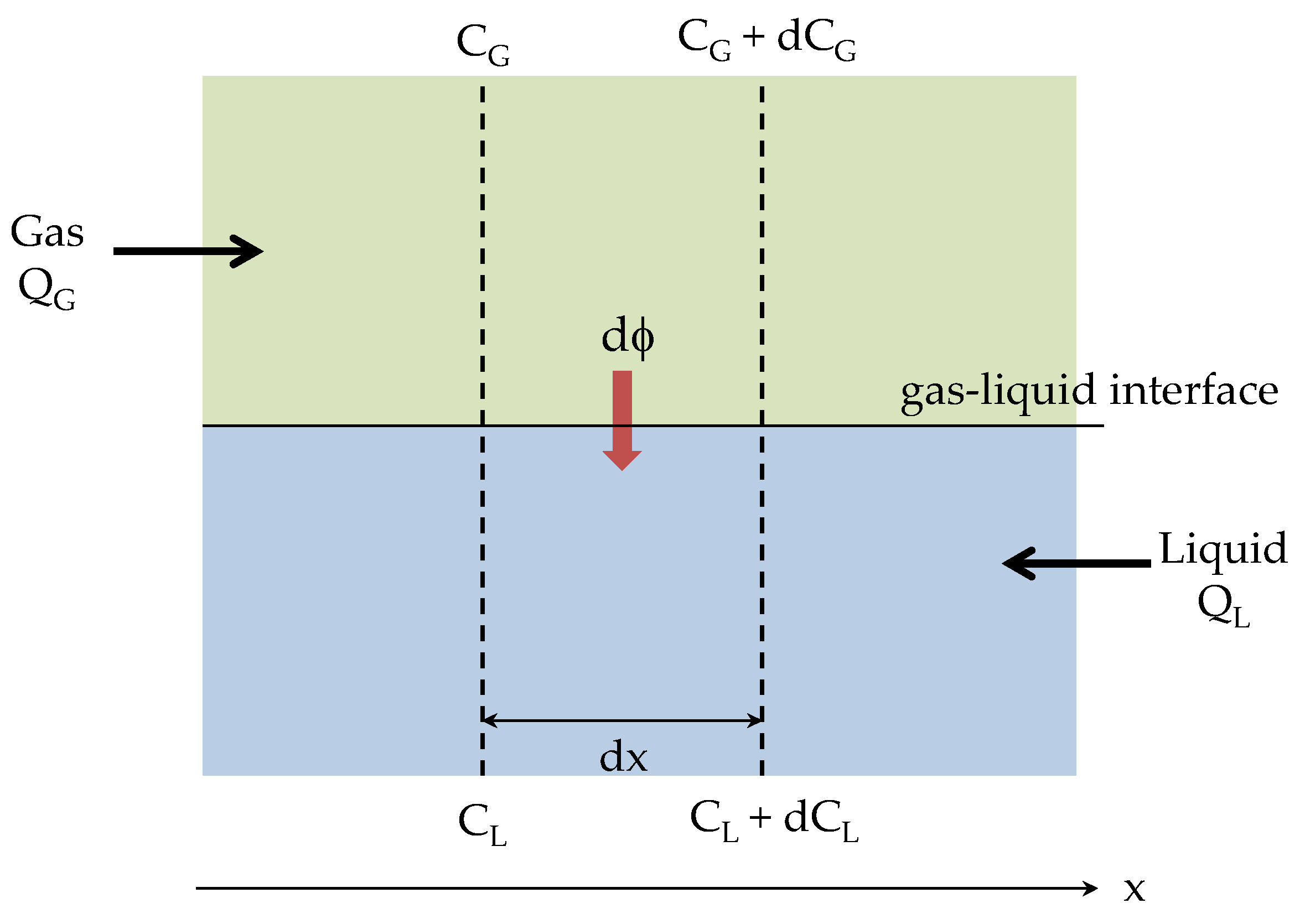
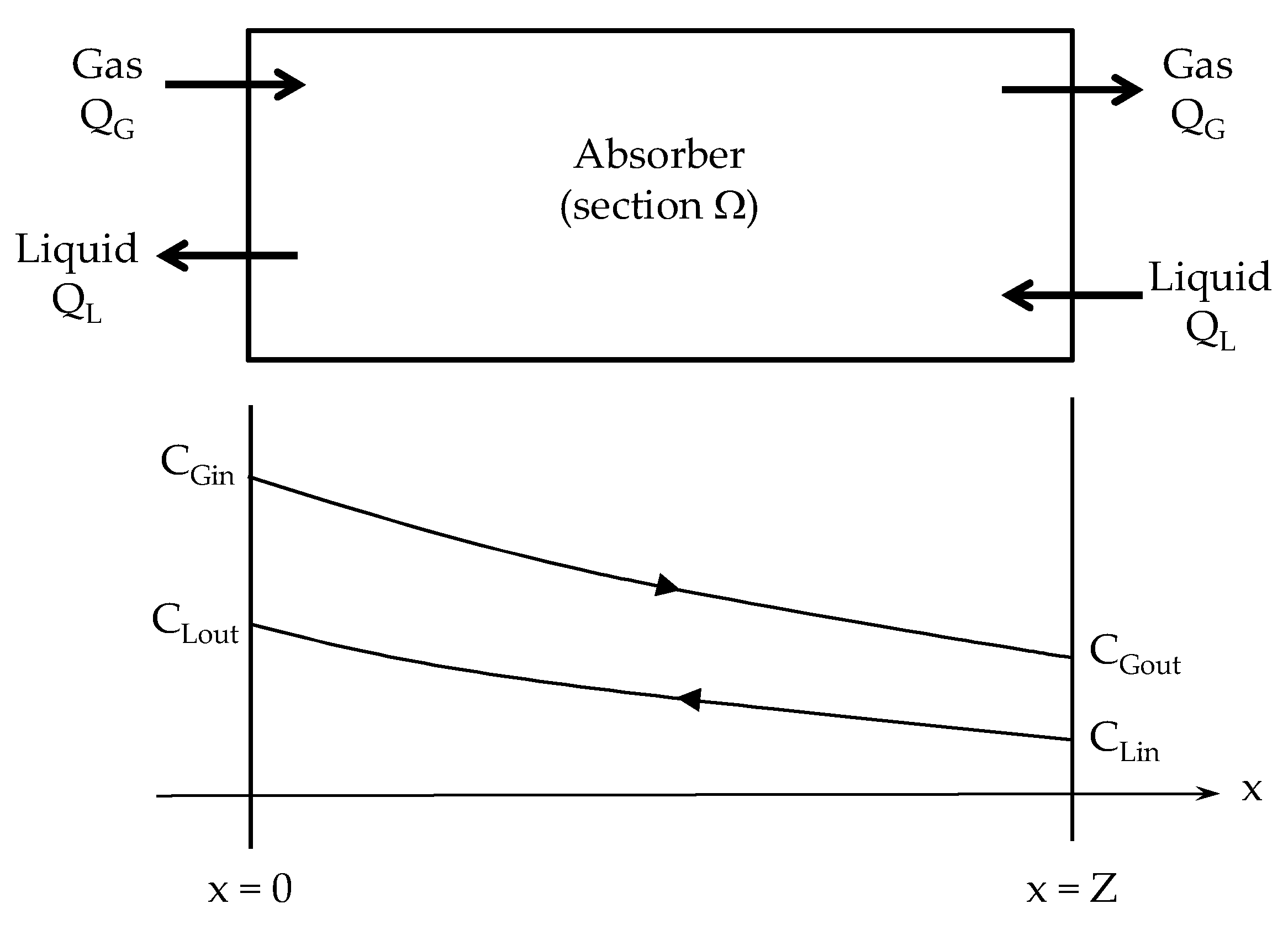
2. Gas–Liquid Absorber Analysis

Although the countercurrent flow in a gas–liquid absorber occurs in vertical devices due to the significant density difference between gas and liquid, the mass balance between the phases was presented horizontally in this study. This was done for convenience, and to facilitate an easier analogy with the heat exchanger (Figure 1 and Figure 2). For dilute concentrations, the gas side mass balance can be written as:
Q G V   C G   =   d ϕ   +   Q G V   ( C G   + dC G )
Then, the amount of the solute transferred from the gas phase is:
d ϕ   =     Q G V   dC G
Similarly for the liquid side:
Q L V   ( C L   + dC L )   +   d ϕ   =   Q L V   C L
d ϕ   =     Q L V   dC L
Consequently:
dC L   =   Q G Q L   dC G
This equation can be rearranged as:
H VOC   dC L   =   H VOC   Q G Q L   dC G   =   1 A   dC G
The flow–rate ratio (HVOC QG/QL) corresponds to the reciprocal of the absorption factor that is usually applied to the design of gas–liquid absorbers. Since the Henry coefficient can be expressed using different definitions, it is necessary to apply the appropriate units. For the purposes of this work, the parameter HVOC was defined as the dimensionless air-to-water concentration ratio (HVOC = CG/CL), which is the most convenient measure for mass distribution calculations. The alternative forms of the Henry coefficient and corresponding conversion factors are given in Reference [9].
Based on the assumption of dilute systems, i.e., the gas flow-rate and liquid flow-rate are constant along the apparatus (Figure 2), where the molar flux ϕ of the transferred solute is:
ϕ   =   Q L V ( C Lout     C Lin )   =   Q G V ( C Gin     C Gout )
Consequently:
C Lout   =   C Lin +   Q G Q L ( C Gin     C Gout )
Change in the solute concentration throughout the length of the absorber can be expressed as:
Q G dC G dx =     Ω   K L a   ( C G H VOC C L )
To adequately integrate this equation, it is useful to make a change in the variables. Thus, using Equation (6):
d ( C G     H VOC   C L )   =   dC G H VOC   dC L = dC G 1 A   dC G = ( 1 1 A ) dC G
Replacing Equation (10) in Equation (9):
Q G ( 1 1 A )   d ( C G   H VOC   C L )   =     Ω   K L a H VOC   ( C G H VOC   C L )   dx
Considering that concentrations of the values CG and CL are given at positions x = 0 and x = Z in Figure 2, the solution to this equation, integrated between x = 0 and x = Z, is:
ln [ ( C Gout     H VOC   C Lin ) ( C Gin     H VOC   C Lout )   ]   =     Ω   Z   K L a H VOC   Q G   ( 1 1 A )
As (ΩZ) is the volume of the apparatus, Equation (12) can be rearranged under the following form:
( C Gout     H VOC   C Lin ) ( C Gin     H VOC   C Lout )   =   exp (   NTU   ( 1 1 A ) )
With:
NTU   =     K L a H VOC   V   Q G
In Equation (14), the dimensionless number of transfer units (NTU) corresponds to the ratio of the gas residence time in the device (V/QG) to the time needed for the mass transfer of the solute from the gas phase to the liquid phase (HVOC/KLa). This NTU parameter can be directly compared to the NTU parameter used in the heat exchanger design (Table 1). Moreover, the reciprocal of the absorption factor (HVOC QG/QL) is also directly comparable to the relative magnitudes of the hot and cold fluid heat capacity rates that are used in the heat exchanger design. Consequently, the analogy with the heat exchanger design implies the definition of the maximum possible mass transfer rate ϕmax between the gas phase and the liquid phase. Assuming a countercurrent absorber of infinite length, the solute concentrations in the gas phase and in the liquid phase are at an equilibrium. Therefore, CGout tends to (HVOC CLin) at x→∞ and:
ϕ max   =   Q G V ( C Gin     H VOC   C Lin )
The effectiveness of the absorber, ε, can be defined as the ratio of the actual mass transfer rate ϕ (Equation (7)) to the maximum possible mass transfer rate ϕmax:
ε   =   ϕ   ϕ max = ( C Gin     C Gout ) ( C Gin     H VOC   C Lin )
According to Equation (16), the solute gas concentration at the outlet of the absorber CGout would tend toward zero only for a countercurrent absorber of infinite length using a solute-free liquid, i.e., CLin = 0. It should be noted that the inlet liquid concentration is usually equal to zero, and consequently ε = (CGin−CGout)/CGin, which corresponds to the equation that is generally applied to determine the absorber efficiency. Combining Equations (8), (13), and (16), the effectiveness of the absorber can be expressed using the following form (calculation details are given in Appendix A):
ε = 1   exp (   NTU   ( A 1 A   ) ) 1   1 A   exp (   NTU   ( A 1 A ) )
Equation (17) becomes identical to the expression used for the countercurrent heat exchanger. The effectiveness versus the NTU is plotted in Figure 3, for various A values. This analogy between countercurrent devices, absorbers, and heat exchangers, can be extended to a gas–liquid stirred tank reactor (STR), as well as to a single stream heat exchanger (typically, a boiler or a condenser). In a gas–liquid STR, the gas flow-rate is dispersed through a known volume of a well-mixed liquid phase, and consequently QL = 0. In this case, the effectiveness of the absorber is presented as (calculation details are given in Appendix B):
ε   =   1     exp (   NTU   )
In the case of a single stream heat exchanger, A tends to ∞, and consequently, the heat exchanger behavior of the apparatus becomes independent of the flow arrangement. As a result, when A→∞, Equation (17) is reduced to Equation (18). The analogies between the heat and mass transfer given in the current paper are summarized in Table 1.

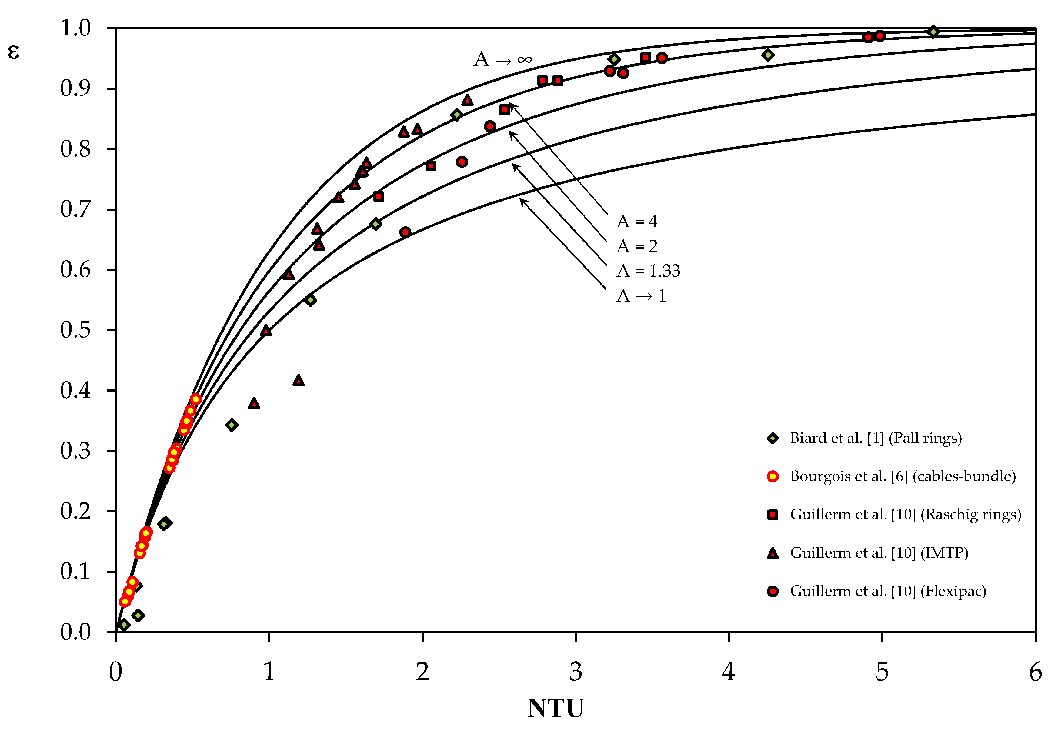
3. Validation of the ε-NTU Method from the Data Reported in the Literature

The aim of this section is to demonstrate that the use of the ε-NTU method permits the calculation of the overall mass transfer coefficient, KLa, of an operating absorber when parameters QL, QG, V, HVOC, and ε are known. The validation is based on data from three studies [1,6,10], as detailed in Table 2. As observed, the experimental data are diversified in terms of solvent used, solutes to be transferred (i.e., various HVOC values), and operating conditions. From the absorption efficiency values reported in these studies, the NTU and KLa values were calculated using Equations (19) and (14), respectively.
NTU = A 1 A ln ( ε 1 ε / A 1 )
All experimental results are reported in Figure 3.

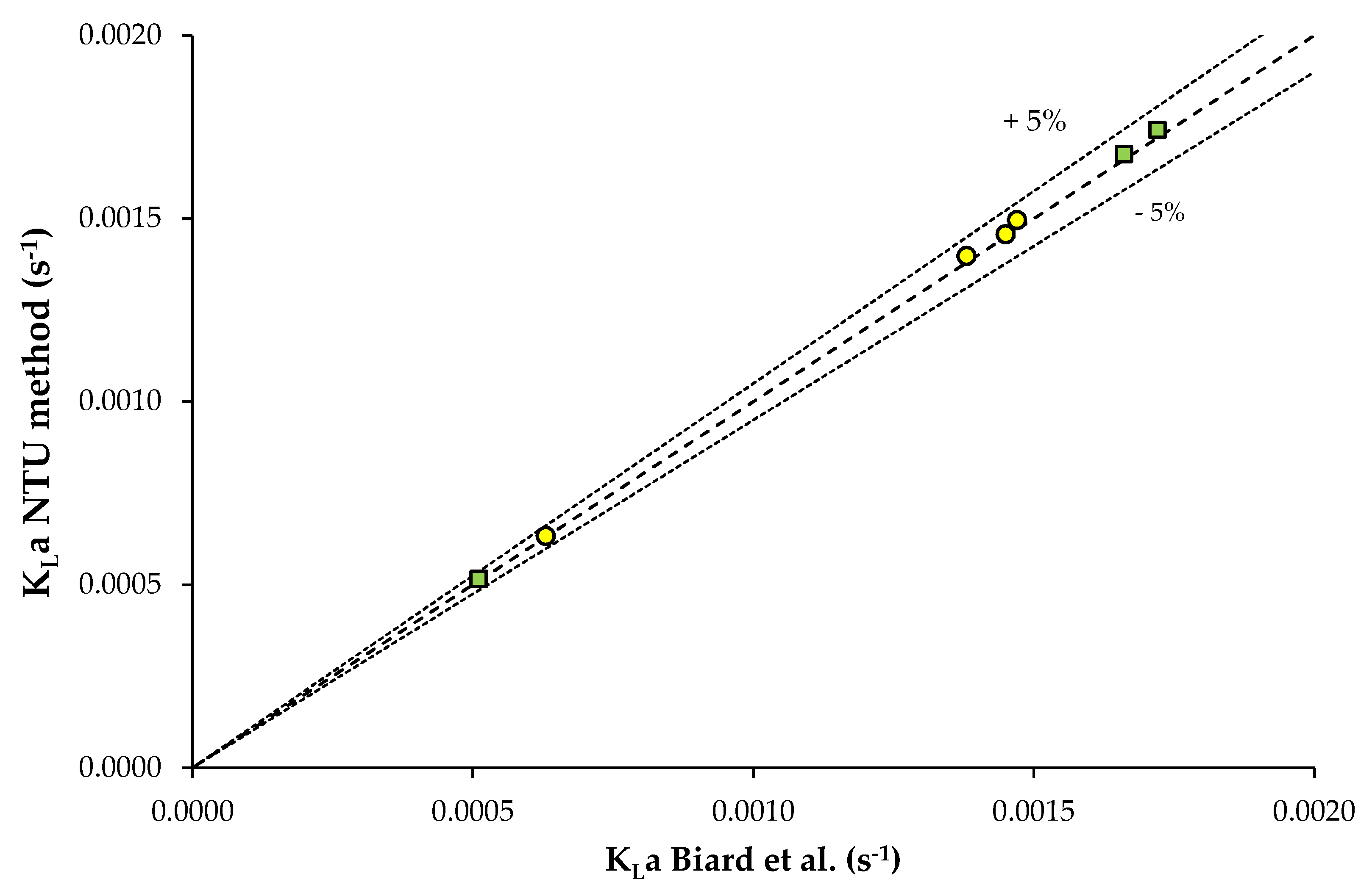
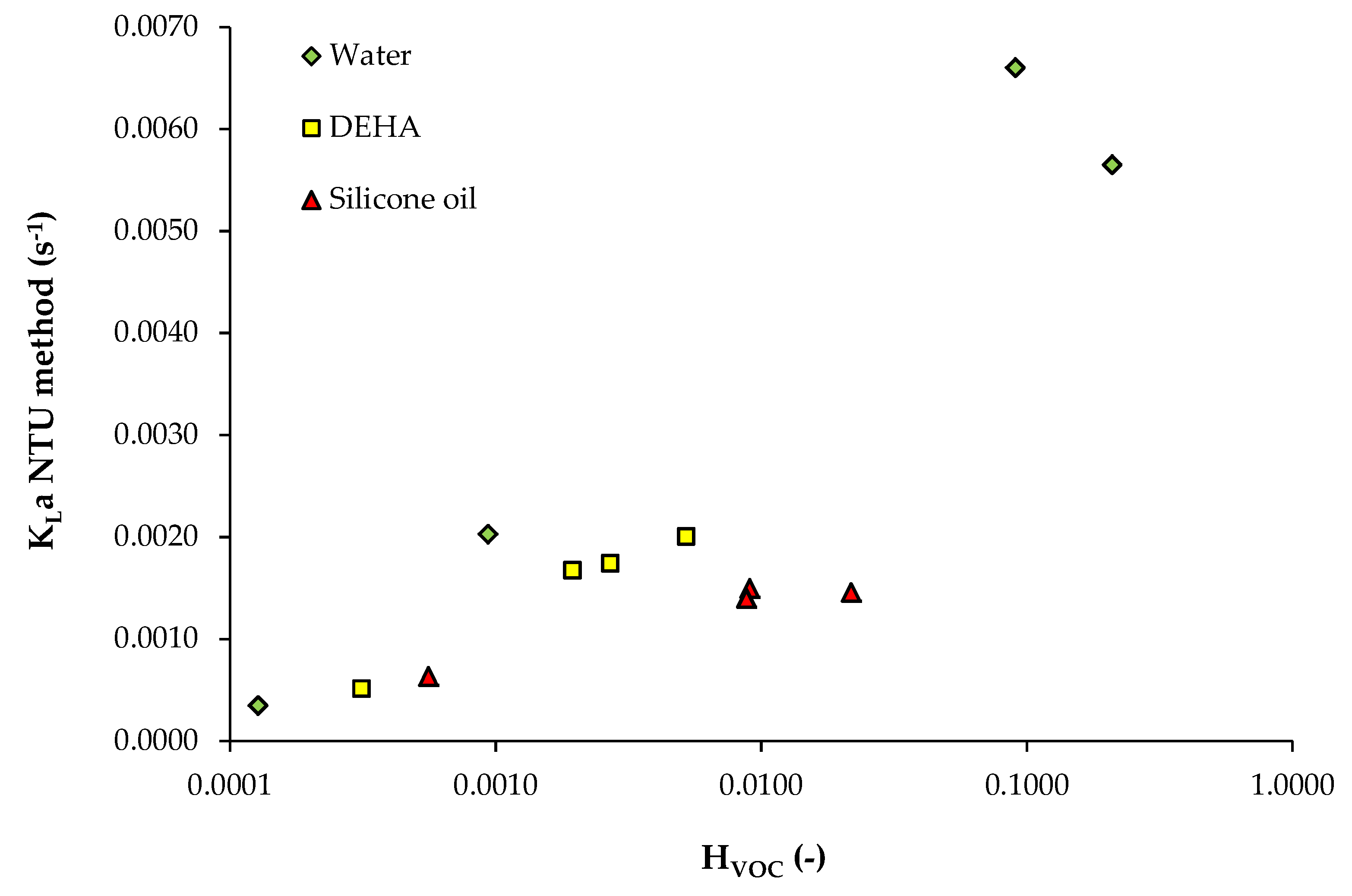
3.1. Data from Study n°1

Biard et al. [1] proposed a simulation of the absorption of hydrophilic and hydrophobic compounds (toluene, dichloromethane, propanol, and acetone) in pure water and pure organic solvents (silicone oil and DEHA, i.e., bis(di-2-ethylhexyl)adipate). A countercurrent column packed with metal Pall rings was used for this purpose. The authors calculated the KLa values according to the Billet–Schultes correlation coupled with the Piché et al. correlation [1]. From the removal efficiencies reported in this study, the ε-NTU method was applied to the 12 cases considered. Results are detailed in Table 3. The KLa values calculated using the ε-NTU method for heavy solvents, i.e., silicone oil and DEHA, were compared to the values determined by the authors from the coupling of the Billet–Schultes and Piché theories (Figure 4). Logically, the results are in good agreement due to the similarity between the definitions used to express the absorber efficiency (i.e., Equation (2) given in Reference [1] and Equation (17) presented in the present paper). Consequently, it could be argued that the ε-NTU method could be a simple, robust, and reliable method to determine the KLa values of operating absorbers. Moreover, the calculation procedure highlights the fact that the KLa mainly depends on the HVOC (Figure 5). Such an expected result was consistent with the mathematical expression of the KLa given in Equation (14).

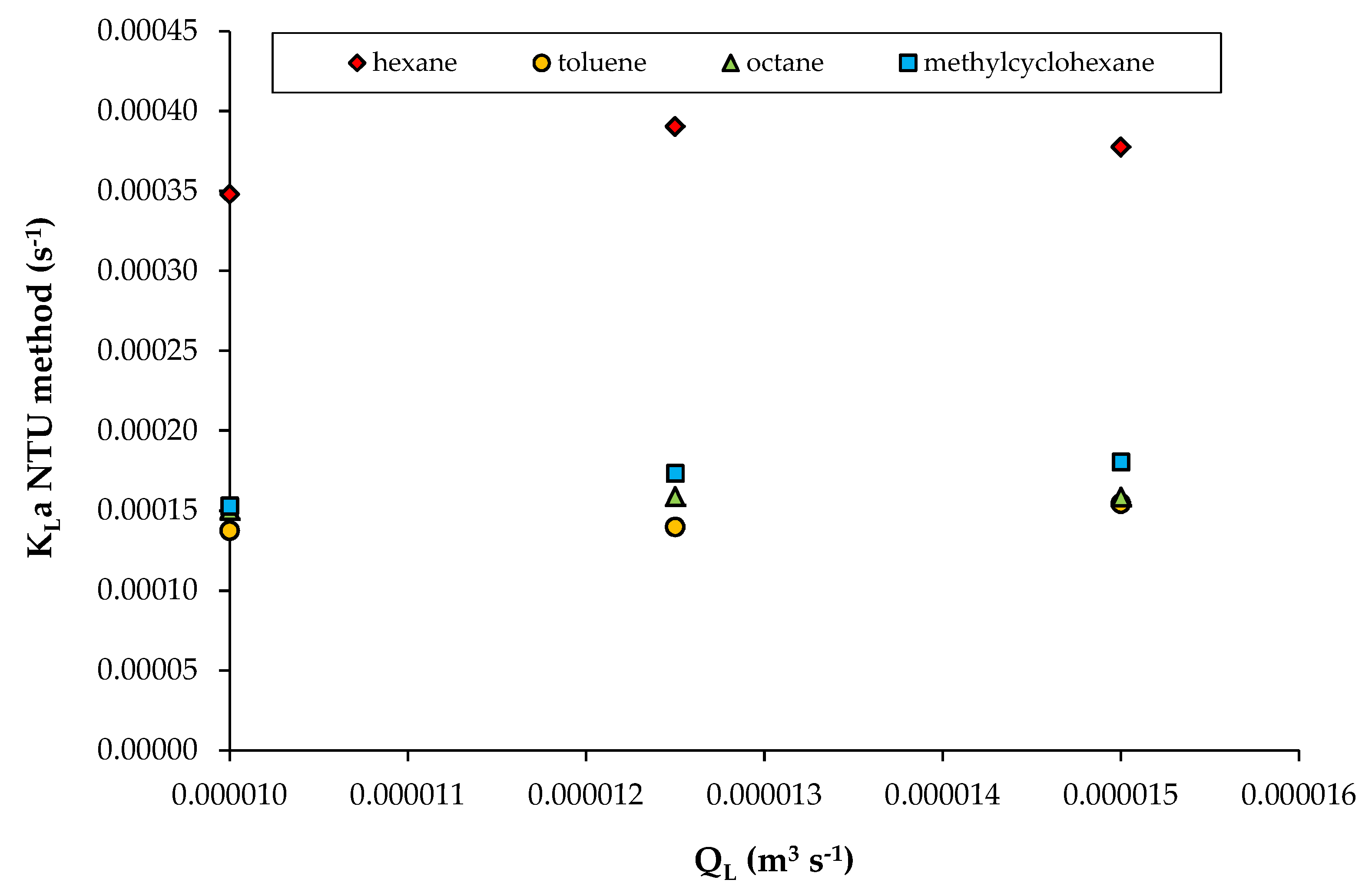
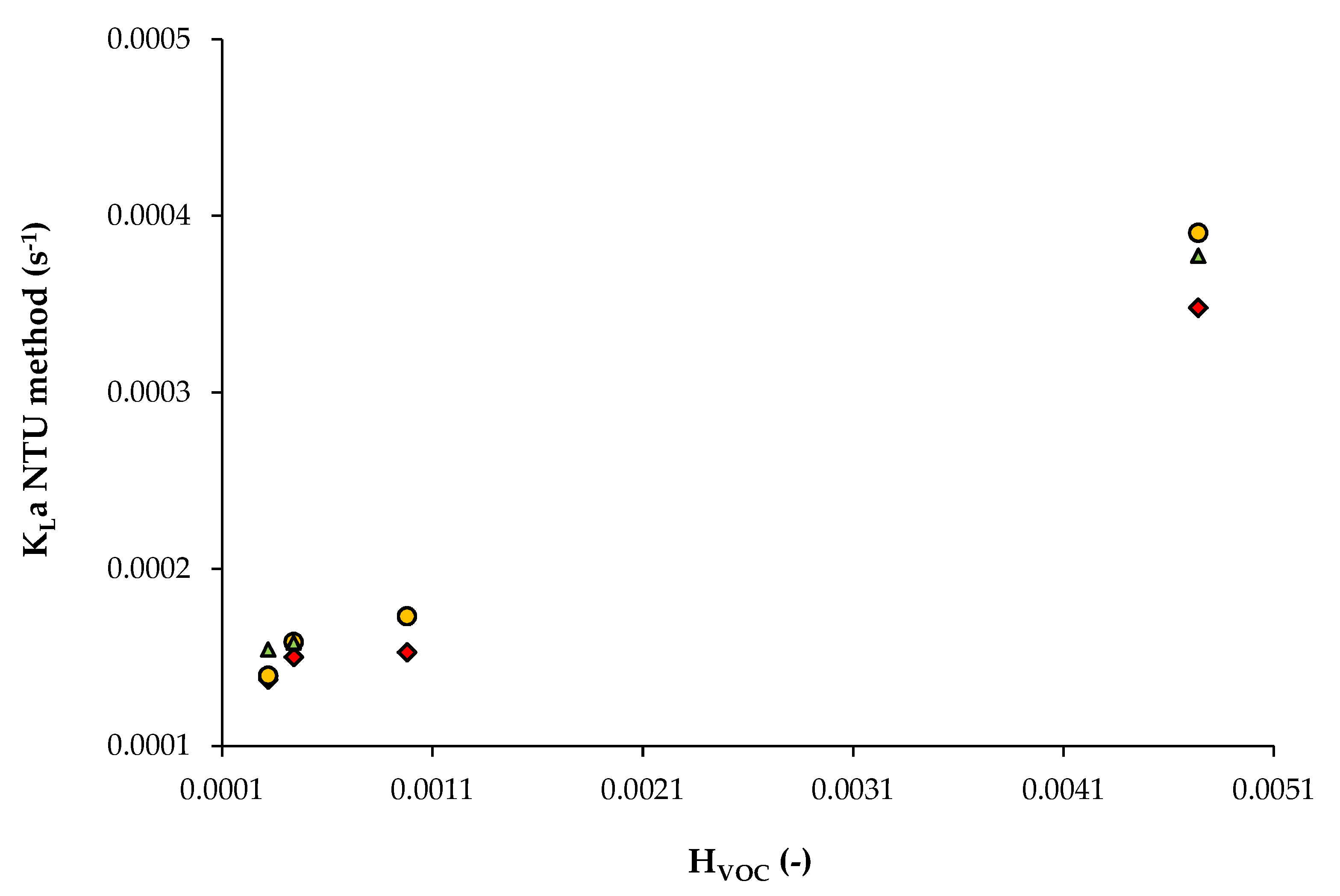
3.2. Data from Study n°2

The main objective of this study was to investigate the absorption of four hydrophobic compounds in pure DEHP (Table 2) using a cables-bundle contactor. Experiments were performed at ambient temperature for three liquid flow-rates. The KLa results obtained using the ε-NTU method are summarized in Table 4. It was clear that regardless of the liquid flow-rate, the same order of magnitude of the KLa was observed for all the investigated compounds, even though the results were slightly higher for hexane (Figure 6). For this solute, the operating conditions led to very low removal efficiencies relative to the low absorption factors. For other compounds (toluene, octane, and methylcyclohexane), the absorption factors ranged from 0.7 to 3.4. Nonetheless, moderated absorption efficiencies were recorded (Figure 3), and these were potentially linked to the viscosity of the DEHP, which explained the low KLa values. According to Figure 6, a slight increase in the KLa relative to the liquid flow-rate was suggested by the authors. The weak influence of the liquid flow-rate in the case of viscous fluid was also reported in the literature [11]. Although the KLa values calculated using the ε-NTU method could not be directly validated in the present case, from the KLa values given by the authors, we observed that these results were still in agreement with the results of Biard et al. [1]. For instance, the influence of the Henry coefficient on the KLa value was confirmed (Figure 7). Moreover, from the solute diffusivities in DEHP given by the authors (toluene: 5.51 × 10⁻¹¹ m2 s−1; hexane: 1.16 × 10⁻¹⁰ m2 s−1; octane: 6.23 × 10⁻¹¹ m2 s−1; methylcyclohexane: 4.24 × 10⁻¹¹ m2 s−1), and knowing that the specific interfacial area determined by the authors was 129 m−1, it was possible to calculate the thickness of the liquid film around the cables available for mass transfer (using the two-film theory) in each experiment. For the four solutes, all the calculated results were in good agreement. The thickness δ of the liquid film around the cables could be estimated from 30 to 56 μm (Table 4).

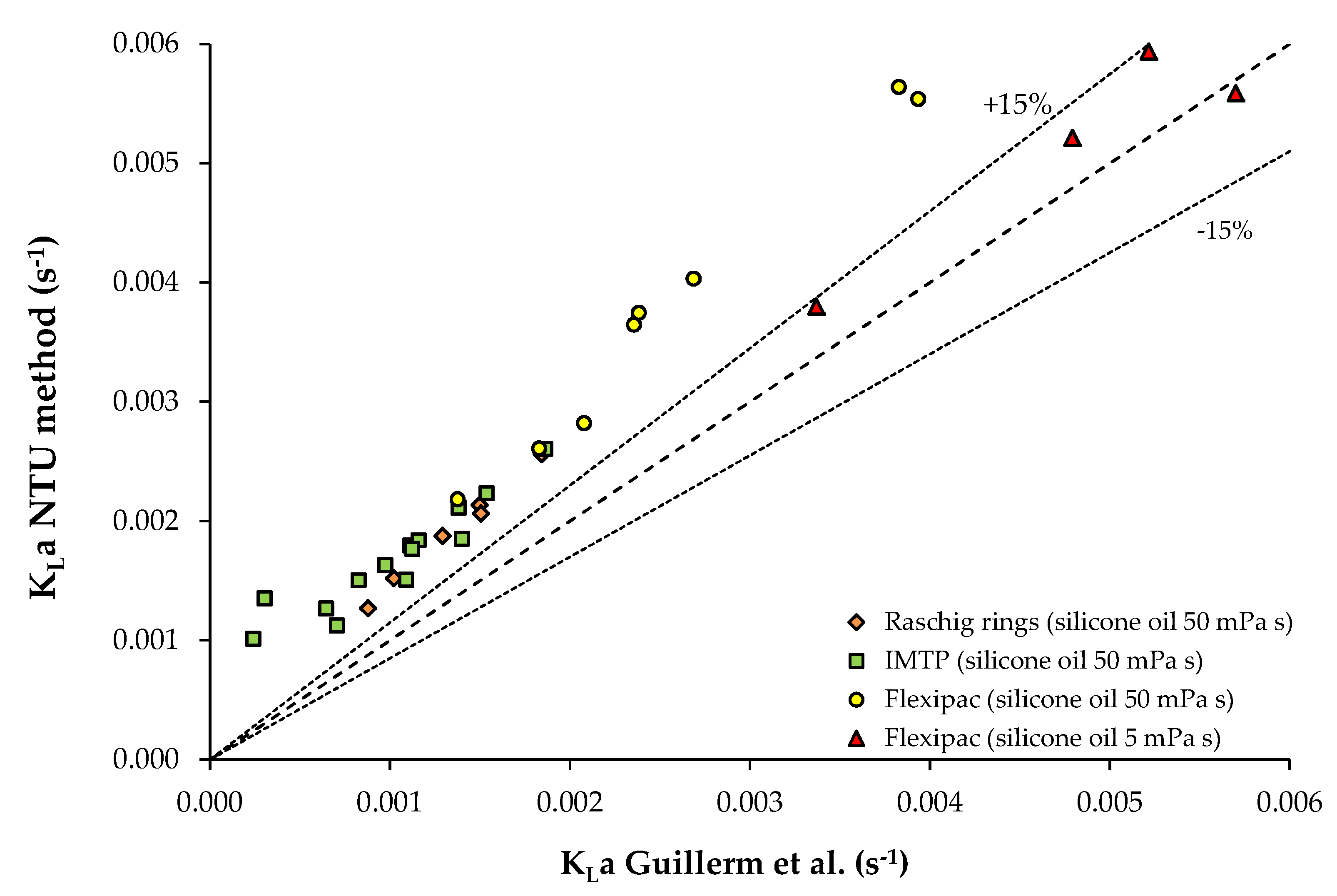
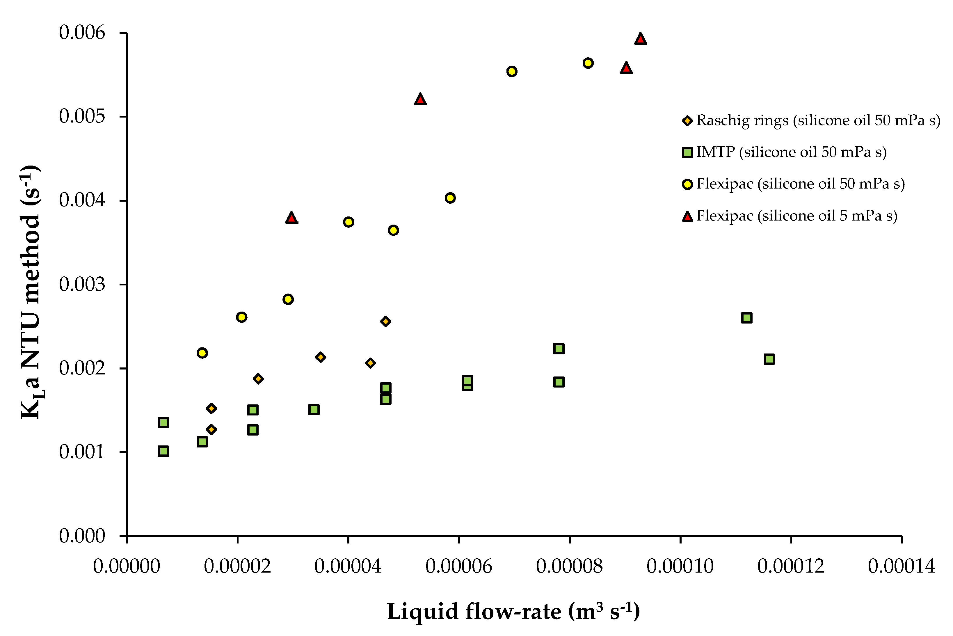
3.3. Data from Study n°3

The purpose of this study was to compare the toluene absorption using two silicone oils with different dynamic viscosities (5 mPa s and 50 mPa s, respectively) in a countercurrent gas-liquid absorber filled with three types of packing material (Raschig rings, IMTP®, and Flexipac®). The KLa values calculated using the ε-NTU method were compared to the values determined by the authors using the following equation reported in Heymes et al. [11].
K L a = Q G V ( C Gin C Gout ) ( C Gin / H VOC C Lout ) ( C Gout / H VOC C Lin ) ln [ ( C Gin / H VOC C Lout ) ( C Gout / H VOC C Lin ) ]
From Figure 8, it appears that the KLa parity plot is validated for the solvent with low dynamic viscosity (5 mPa s). Conversely, for the solvent with the high dynamic viscosity (50 mPa s), the KLa determined using the ε-NTU method was usually 30% higher than the values calculated using Equation (20). According to this equation, the KLa determination required the measurement of solute concentrations in the gas phase and in the liquid phase. As the concentration measurement of a solute in a viscous fluid could be relatively inaccurate, the KLa determination using Equation (20) should be considered cautiously. Consequently, the KLa determination using the ε-NTU method should be preferred, since only the inlet and outlet gaseous concentrations are needed. Results from this study also confirmed that the viscosity of the liquid, as well as the type of packing material filling the column, has a considerable impact on the volumetric mass transfer coefficient of the operating absorber (Figure 9).

4. Conclusions

We adapted the ε-NTU method, which is usually applied to heat exchanger design, to gas–liquid countercurrent absorbers. We demonstrated that this method could be successfully adapted to determine the overall mass transfer coefficient of the absorber in operation, the KLa, using advance knowledge of the physical parameters: HVOC, QG, QL, V, CGin, and CGout. Therefore, the ε-NTU method may be a robust and reliable tool for the KLa determination of gas–liquid contactors used in environmental applications for treating the removal of air pollutants. Consequently, new empirical correlations for the prediction of KLa for heavy viscous solvents may be developed. Moreover, since this method only requires the measurement of solute concentrations in the gas phase, it should be efficient in determining the KLa values of complex systems, such as Two-Phase Partitioning bioreactors (TPPB) used to remove hydrophobic pollutants using mixtures of immiscible liquids. In such a case, the main difficulty lies in the knowledge of the HVOC. As a result, the ε-NTU method must be combined with the “equivalent absorption capacity” concept [12,13], thereby enabling calculation of the physical properties of the mixture [14].

Funding

This research received no external funding.

Conflicts of Interest

The author declares no conflict of interest.

Nomenclature

absorber
aspecific interfacial area (m−1)
Aabsorption factor
Cconcentration (mol m−3)
EBRTEmpty Bed Residence Time (s)
HHenry coefficient
kG, kLlocal mass transfer coefficients (m s−1)
KGa, KLaoverall mass transfer coefficients (s−1)
NTUNumber of Transfer Units
Qflow-rate (m3 s−1)
Vpacking volume (m3)
Zpacking height (m)
Greek letters
δfilm thickness (m)
εeffectiveness
Ωcross sectional area (m2)
ϕmolar flux (mol m−3 s−1)
Subscripts
Ggas
ininlet
Lliquid
Maxmaximum
outoutlet
VOCVolatile Organic Compound
heat exchanger, Table 1
Aheat-transfer area (m2)
Cheat capacity rate of the fluid = M Cp (W K−1)
Cpspecific heat capacity (J kg−1 K−1)
Mflow rate (kg s−1)
NTUNumber of Transfer Units
Ttemperature (K)
Uheat transfer coefficient (W m−2 K−1)
Greek letters
ΔTMLlog mean temperature difference (K)
εeffectiveness
ϕpower, heat transferred per unit time (W)
Subscripts
ccold
hhot
ininlet
Maxmaximum
Minminimum
outoutlet

Appendix A. ε-NTU Relationship for a Gas-Liquid Absorber

Equations (8), (13), and (16) are rewritten:
C Lout   =   C Lin +   Q G Q L ( C Gin     C Gout )
( C Gout     H VOC   C Lin ) ( C Gin     H VOC   C Lout )   =   exp (   NTU   ( 1 1 A ) )   =   β  
ε   =   ϕ   ϕ max = ( C Gin   C Gout ) ( C Gin     H VOC   C Lin )
Multiplying Equation (A1) by (−HVOC) gives:
H VOC   C Lout   =   H VOC   C Lin   H VOC   Q G Q L ( C Gin     C Gout )
H VOC   C Lout   =   H VOC   C Lin   1 A   ( C Gin     C Gout )
Introducing Equation (A5) in Equation (A2):
( C Gout     H VOC   C Lin ) ( C Gin   -   H VOC   C Lin   1 A   ( C Gin     C Gout ) )   =   β  
Rearranging Equation (A6):
H VOC   C Lin   =   C Gout ( β / A 1 β 1 ) +   C Gin   β ( 1 1 / A β 1 )
Introducing Equation (A7) in Equation (A3):
ε   =   ( C Gin     C Gout ) ( β 1 ) ( β 1 ) C Gin [ C Gout ( β / A 1 )   +   C Gin β ( 1 1 / A ) ]
Rearranging Equation (A8):
ε   =   ( 1 β ) ( C Gout     C Gin ) ( 1 β / A ) ( C Gout     C Gin )
As β = exp(−NTU(1−1/A)), Equation (A9) can be rewritten under the final form:
ε = 1   exp (   NTU   ( A 1 A ) ) 1   1 A   exp (   NTU   ( A 1 A ) )

Appendix B. Gas-Liquid Stirred Tank Reactor (STR)

In a gas–liquid stirred tank reactor (STR), a gas flow-rate, QL, continuously bubbles through a known volume, V, of the well-mixed liquid phase. The solute mass transfer from the gas to the liquid phase is expressed as:
dC G dt =     K L a   ( C G H VOC C L )
During the mean residence time of the gas in the liquid phase, t = V/QG, the solute concentration in the rising gas bubbles changes from CGin to CGout, and consequently:
H VOC C Gin C Gout dC G ( C G   H VOC   C L ) =     K L a   t = 0 t = V / Q G dt
ln [ ( C Gout   -   H VOC   C L ) ( C Gin   -   H VOC   C L )   ]   =   K L a H VOC     V Q G
Defining NTU = (KLa V)/(HVOC QG), Equation (A13) becomes:
C Gout   =   H VOC   C L   ( 1 exp ( NTU ) )   +   C Gin   exp   ( NTU )
Moreover, the molar flux ϕ of the transferred solute is:
ϕ   =   Q G V ( C Gin     C Gout )
Introducing the expression of CGout (Equation (A14)) in Equation (A15) gives:
ϕ   =   Q G V ( 1 exp ( NTU ) ) ( C Gin     H VOC   C L )
where the term (1−exp(−NTU)) is the solute fraction that can be transferred from the gas phase to the liquid phase. Basically, for industrial applications, the initial concentration of the liquid phase is CL = 0. Consequently:
ϕ   =   Q G V ( 1 exp ( NTU ) )   C Gin
According to the NTU expression, the maximum solute fraction that can be transferred is obtained for a long residence time of the gas phase in the liquid phase (i.e., using a large liquid volume and a small gas flow-rate). In that case, the NTU is significantly higher than 1 and exp(−NTU) tends to 0. As a result:
ϕ max   =   Q G V   C Gin
The effectiveness of the STR is then:
ε   =   ϕ ϕ max   =   1     exp (   NTU   )  

References

  1. Biard, P.-F.; Couvert, A.; Giraudet, S. Volatile organic compounds absorption in packed column: Theoretical assessment of water, DEHA and PDMS 50 as absorbents. J. Ind. Eng. Chem. 2018, 59, 70–78. [Google Scholar] [CrossRef]
  2. Dumont, E.; Delmas, H. Mass transfer enhancement of gas absorption in oil-in-water systems: A review. Chem. Eng. Process. Process Intensif. 2003, 42, 419–438. [Google Scholar] [CrossRef]
  3. Mackowiak, J. Fluid Dynamics of Packed Columns: Principles of the Fluid Dynamic Design of Columns for Gas/Liquid and Liquid/Liquid Systems; Chemische Technik/Verfahrenstechnik; Springer: Berlin/Heidelberg, Germany, 2010; ISBN 978-3-540-88780-5. [Google Scholar]
  4. Fair, J.; Steinmeyer, D.; Penney, W.; Corcker, B. Gas absorption and gas-liquid system design. In Perry’s Chemical Engineers’ Handbook, 8th ed.; Perry, R.H., Green, D.W., Eds.; McGraw-Hill: New York, NY, USA, 2008; pp. 14-1–14-98. [Google Scholar]
  5. Sinnott, R. Coulson and Richardson’s Chemical Engineering Volume 6 (Design); Pergamon Press: Oxford, UK, 1994; Volume 6, ISBN 0-08-041865-1. [Google Scholar]
  6. Bourgois, D.; Vanderschuren, J.; Thomas, D. Study of mass transfer of VOCs into viscous solvents in a pilot-scale cables-bundle scrubber. Chem. Eng. J. 2009, 145, 446–452. [Google Scholar] [CrossRef]
  7. Garcia-Ochoa, F.; Gomez, E. Bioreactor scale-up and oxygen transfer rate in microbial processes: An overview. Biotechnol. Adv. 2009, 27, 153–176. [Google Scholar] [CrossRef] [PubMed]
  8. Russell, T.W.F.; Robinson, A.S.; Wagner, N.J. Mass and Heat Transfer: Analysis of Mass Contactors and Heat Exchangers; Cambridge Series in Chemical Engineering; Cambridge University Press: Cambridge, UK; New York, NY, USA, 2008; ISBN 978-0-521-88670-3. [Google Scholar]
  9. Staudinger, J.; Roberts, P.V. A critical compilation of Henry’s law constant temperature dependence relations for organic compounds in dilute aqueous solutions. Chemosphere 2001, 44, 561–576. [Google Scholar] [CrossRef]
  10. Guillerm, M.; Couvert, A.; Amrane, A.; Norrant, E.; Lesage, N.; Dumont, É. Absorption of toluene in silicone oil: Effect of the solvent viscosity on hydrodynamics and mass transfer. Chem. Eng. Res. Des. 2016, 109, 32–40. [Google Scholar] [CrossRef]
  11. Heymes, F.; Manno Demoustier, P.; Charbit, F.; Louis Fanlo, J.; Moulin, P. Hydrodynamics and mass transfer in a packed column: Case of toluene absorption with a viscous absorbent. Chem. Eng. Sci. 2006, 61, 5094–5106. [Google Scholar] [CrossRef]
  12. Dumont, E.; Darracq, G.; Couvert, A.; Couriol, C.; Amrane, A.; Thomas, D.; Andrès, Y.; Le Cloirec, P. Determination of partition coefficients of three volatile organic compounds (dimethylsulphide, dimethyldisulphide and toluene) in water/silicone oil mixtures. Chem. Eng. J. 2010, 162, 927–934. [Google Scholar] [CrossRef]
  13. Dumont, E.; Darracq, G.; Couvert, A.; Couriol, C.; Amrane, A.; Thomas, D.; Andrès, Y.; Le Cloirec, P. VOC absorption in a countercurrent packed-bed column using water/silicone oil mixtures: Influence of silicone oil volume fraction. Chem. Eng. J. 2011, 168, 241–248. [Google Scholar] [CrossRef]
  14. Dumont, É. Mass Transfer in Multiphasic Gas/Liquid/Liquid Systems. KLa Determination Using the Effectiveness-Number of Transfer Unit Method. Processes 2018, 6, 156. [Google Scholar] [CrossRef]
Figure 1. Nomenclature for the material balances in a countercurrent gas–liquid absorber.
Chemengineering 03 00057 g001
Figure 2. Concentration profile throughout the length of the gas–liquid countercurrent absorber.
Chemengineering 03 00057 g002
Figure 3. Effectiveness (ε) of a countercurrent gas–liquid absorber versus the number transfer units (NTU).
Chemengineering 03 00057 g003
Figure 4. KLa parity plot obtained from the data analysis reported in Biard et al. [1] (circles: silicone oil; squares: DEHA; water data not provided by the authors).
Chemengineering 03 00057 g004
Figure 5. KLa versus the Henry coefficient (HVOC) from the data analysis reported in Biard et al. [1]. For all the simulations: gas flow-rate = 1.20 m3/s (gas EBRT = 2 s); liquid flow-rate = 3.06 × 10⁻³ m3/s; and V = 2.36 m3 (T = 20 °C).
Chemengineering 03 00057 g005
Figure 6. KLa versus liquid flow-rate (from the data analysis reported in Reference [6]).
Chemengineering 03 00057 g006
Figure 7. KLa versus Henry coefficient (from the data analysis reported in Reference [6]). Diamond: gas flow-rate = 1.0 × 10⁻⁵ m3/s; circle: gas flow-rate = 1.25 × 10⁻⁵ m3/s; square: gas flow-rate = 1.50 × 10⁻⁵ m3/s.
Chemengineering 03 00057 g007
Figure 8. KLa parity plot obtained from the data analysis reported in Reference [10], (V = 1.13 × 10⁻² m3; T = 25 °C).
Chemengineering 03 00057 g008
Figure 9. KLa versus the liquid flow-rate (calculated from Reference [10], (V = 1.13 × 10⁻² m3; T = 25 °C).
Chemengineering 03 00057 g009
Table 1. The effectiveness-NTU method for the countercurrent devices. Analogy between the gas–liquid mass absorber and the heat exchanger (see nomenclature for details).
Mass AbsorberHeat Exchanger
Physical parameterConcentration C (mol m−3)Temperature T (K)
Transfer coefficientKL (m s−1)U (W m−2 K−1)
Transfer surface areaa V (m2)A (m2)
Transfer rate ϕ   =   Q L V ( C Lout     C Lin )
ϕ   =   Q G V ( C Gin     C G out )
ϕ   = K L a   Δ C M L
(mol m−3 s−1)
ϕ   =   M c   C p c   ( T cout     T cin )
ϕ   =   M h   C p h   ( T hin     T h o u t )
ϕ   = U   A   Δ T M L
(W)
Maximum possible transfer rate ϕ max   = Q G V   ( C G i n H V O C C L i n )
(mol m−3 s−1)
ϕ max   =   C min   ( T hin T cin )
(W)
Effectiveness
(dimensionless)
ε   =   ϕ   ϕ max
ε   =   ( C Gin     C G o u t ) ( C Gin     H V O C   C L i n )
ε = 1     exp (   NTU   ( 1 1 A ) ) 1     1 A   exp (   NTU   ( 1 1 A ) )
ε   =   m a x ( ( T cout     T c i n ) , ( T hin   T h o u t ) ) ( T h i n T c i n )
ε = 1     exp (   NTU   ( 1 R ) ) 1   R   exp (   NTU   ( 1 R ) )
1 A = H V O C   Q G Q L R =   C m i n C m a x
NTU (dimensionless)   K L a H VOC   V   Q G U   A   C min
Table 2. Literature data used for the KLa determination using the ε-NTU method.
SolventSoluteHVOCOperating ConditionsRef
Water 1 mPa sToluene
Dichloromethane
Propanol
Acetone
2.09 × 10⁻¹
9.03 × 10⁻²
1.27 × 10⁻⁴
9.36 × 10⁻⁴
V = 2.36 m3
Packed column (Pall rings)
QL = 3.06 × 10⁻³ m3/s
QG: 1.20 m3/s
(gas EBRT: 2 s)
20 °C
Study n°1
[1]
DEHA (bis(di-2-ethylhexyl)adipate) 12.5 mPa sToluene
Dichloromethane
Propanol
Acetone
3.12 × 10⁻⁴
1.94 × 10⁻³
2.70 × 10⁻³
5.21 × 10⁻³
Silicone oil 50 mPa sToluene
Dichloromethane
Propanol
Acetone
5.58 × 10⁻⁴
9.04 × 10⁻³
8.79 × 10⁻³
2.17 × 10⁻²
DEHP (di-2-ethylhexyl phthalate) 76 mPa sHexane
Toluene
Octane
Methylcyclohexane
4.74 × 10⁻³
3.19 × 10⁻⁴
4.40 × 10⁻⁴
9.79 × 10⁻⁴
V = 1.46 × 10⁻² m3
Cables-bundle contactor
QL = 1.00 × 10⁻⁵; 1.25 × 10⁻⁵; 1.50 × 10⁻⁵ m3/s
QG: 1.39 × 10⁻² m3/s
(gas EBRT: 1 s)
20 °C
Study n°2
[6]
Silicone oil 50 mPa sToluene1.17 × 10−3V = 1.13 × 10⁻² m3
Packed column (Raschig rings)
QL = 1.53 × 10⁻⁵–4.58 × 10⁻⁵ m3/s
QG: 7.15 × 10⁻³ m3/s
(gas EBRT: 1.6 s)
25 °C
Study n°3
[10]
Silicone oil 50 mPa sToluene1.17 × 10−3V = 1.13 10−2 m3
Packed column (IMTP®)
QL = 6.62 × 10⁻⁶–1.16 × 10⁻⁴ m3/s
QG: 1.10 × 10⁻² m3/s
(gas EBRT: 1 s)
25 °C
Study n°3
[10]
Silicone oil 50 mPa s
Silicone oil 5 mPa s
Toluene
Toluene
1.17 × 10⁻³
1.09 × 10⁻³
V = 1.13 × 10⁻² m3
Packed column (Flexipac®)
QL = 1.36 × 10⁻⁵–9.28 × 10⁻⁵ m3/s
QG: 1.10 × 10⁻² m3/s
(gas EBRT: 1 s)
25 °C
Study n°3
[10]
Table 3. KLa determination using the data reported in Biard et al. [1]. For all the simulations: gas flow-rate = 1.20 m3/s (gas EBRT = 2 s); liquid flow-rate = 3.06 × 10⁻³ m3/s; and V = 2.36 m3 (T = 20 °C).
Solute HVOC (-)A (-)ε (-)NTU (-)KLa (s−1)
TolueneWater0.209360.0120.0120.0535.63 × 10−3
DEHA0.000318.1620.9493.2515.17 × 10−4
PDMS500.000564.5610.8572.2256.33 × 10−4
DichloromethaneWater0.090310.0280.0280.1446.60 × 10−3
DEHA0.001941.3110.6761.6951.68 × 10−3
PDMS500.009040.2820.1810.3251.50 × 10−3
PropanolWater0.0001320.0090.9945.3313.46 × 10−4
DEHA0.002700.9440.5501.2691.74 × 10−3
PDMS500.008790.2900.1790.3121.40 × 10−3
AcetoneWater0.000942.7210.9564.2542.03 × 10−3
DEHA0.005210.4880.3430.7562.01 × 10−3
PDMS500.021740.1170.0770.1321.46 × 10−3
Table 4. KLa determination using the data reported in Bourgois et al. [6]. For all the experiments, solvent: DEHP (di-2-ethylhexyl phtalate); gas flow-rate = 1.39 × 10⁻² m3/s (gas EBRT = 1 s; V = 1.46 × 10⁻² m3).
SoluteHVOC (-)QL (m3/s)A (-)ε (-)NTU (-)KLa (s−1)δ (m)
Hexane4.7 × 10−31.00 × 10−50.1520.0590.0773.48 × 10−44.30 × 10⁻⁵
1.25 × 10−50.1900.0680.0873.94 × 10−43.80 × 10⁻⁵
1.25 × 10−50.1900.0670.0863.87 × 10−43.87 × 10⁻⁵
1.50 × 10−50.2280.0510.0592.67 × 10−45.59 × 10⁻⁵
1.50 × 10−50.2280.0830.1084.87 × 10−43.07 × 10⁻⁵
Toluene3.2 × 10−41.00 × 10−52.2570.3450.4621.40 × 10−45.07 × 10⁻⁵
1.00 × 10−52.2570.3350.4441.35 × 10−45.27 × 10⁻⁵
1.25 × 10−52.8210.3460.4551.38 × 10−45.15 × 10⁻⁵
1.25 × 10−52.8210.3510.4641.41 × 10−45.05 × 10⁻⁵
1.25 × 10−52.8210.350.4621.40 × 10−45.07 × 10⁻⁵
1.50 × 10−53.3860.3670.4861.48 × 10−44.82 × 10⁻⁵
1.50 × 10−53.3860.3860.5201.58 × 10−44.50 × 10⁻⁵
1.50 × 10−53.3860.3860.5201.58 × 10−44.50 × 10⁻⁵
Octane4.4 × 10−41.00 × 10−51.6360.2720.3491.46 × 10−45.50 × 10⁻⁵
1.00 × 10−51.6360.2840.3691.54 × 10−45.21 × 10⁻⁵
1.25 × 10−52.0450.3040.3941.65 × 10−44.87 × 10⁻⁵
1.25 × 10−52.0450.2860.3641.53 × 10−45.27 × 10⁻⁵
1.50 × 10−52.4550.2980.3791.58 × 10−45.07 × 10⁻⁵
1.50 × 10−52.4550.2980.3791.58 × 10−45.07 × 10⁻⁵
Methylcyclo-hexane9.8 × 10−41.00 × 10−50.7350.1440.1741.62 × 10−43.38 × 10⁻⁵
1.00 × 10−50.7350.1310.1551.44 × 10−43.79 × 10⁻⁵
1.25 × 10−50.9190.1580.1891.76 × 10−43.10 × 10⁻⁵
1.25 × 10−50.9190.1430.1681.57 × 10−43.49 × 10⁻⁵
1.25 10−50.9190.1660.2011.87 × 10−42.92 × 10⁻⁵
1.50 × 10−51.1030.1630.1931.80 × 10−43.04 × 10⁻⁵
1.50 × 10−51.1030.1640.1941.81 × 10−43.02 × 10⁻⁵

