Abstract
Background: The cargo stowage and securing plan for non-standardized cargo is vital for ensuring safety at sea, as improper placement or inadequate lashing can compromise maritime transport safety. Due to the diverse size and type of cargo, efficient planning is also essential to optimize space utilization and improve the economic performance of general cargo vessels. Methods: This paper presents a novel methodology to identify the optimal cargo securing layout using lashing lines that comply with international standards while minimizing deck space usage. A comparative analysis of two major securing guidelines was conducted to determine the stricter and safer standard. Results: The optimization approach was validated with real-world case studies, revealing the most effective securing configurations. These are defined by the optimal combination of vertical and horizontal lashing angles, which secure cargo in any stowage position by balancing longitudinal and transverse forces while minimizing occupied deck area. Additionally, novel graphs and 3D maps are introduced to illustrate the relationships between key securing parameters. Conclusions: The obtained results and the visual tools enhance understanding and provide practical support for lashing planners, facilitating safer and more efficient cargo securing decisions.
1. Introduction
In 2023, a total of 1244 cargo ships were involved in reported marine casualties and incidents—more than any other ship type, including passenger ships, fishing vessels, service ships, and others [1]. Moreover, in the cargo ship sector during the period 2014–2023, 59.3% of accident event types were related to human actions, while 23.0% were attributed to system or equipment failures. Regarding contributing factors over the same period, 10.1% of incidents were linked to deficiencies in rules, procedures, and training, and 47.4% were attributed to human behavior [1].
Nowadays, the identification and prediction of maritime accident factors are increasingly supported by artificial intelligence techniques [2]. A significant number of these incidents have been associated with ineffective cargo securing methods, leading to cargo shifting that can compromise both vessel navigation and cargo safety [3]. The International Maritime Organization (IMO) emphasizes that proper stowage and securing methods are essential to ensuring the safety of life at sea.
Historically and in the present, improper stowage and securing practices have caused numerous and serious maritime casualties, resulting in injuries and fatalities among crewmembers—both during navigation and during loading and unloading operations at ports. In addition to the tragic loss of life, such accidents often lead to substantial economic losses due to damage to other cargo, the ship itself, and the environment. Therefore, cargo must be properly stowed and secured on board to prevent exposing the vessel, its cargo, crew, and the environment to unnecessary risks.
The objective of this paper is twofold: (i) to analyze the most relevant international standards for cargo securing, providing practical insights for maritime operators, and (ii) to develop and present an optimized stowage and securing plan specifically designed for vessels transporting non-standardized cargoes. This approach aims to improve operational efficiency and reduce labor costs.
To achieve this, key guidelines and standards were applied, notably the Code of Safe Practice for Cargo Stowage and Securing (CSS Code) issued by the International Maritime Organization (IMO) [4] and the standard published by the classification society DNV 2024 [5].
The CSS Code represents the principal IMO regulation addressing the stowage and securing of non-standardized cargo. It emphasizes that the safety of such operations depends on proper planning, execution, and supervision by adequately trained and experienced personnel [4]. The application of this code has been widely referenced in prior research analyzing the effectiveness of securing systems for irregular cargoes [6,7].
In addition, standards developed by classification societies are frequently used for comparative assessments. For instance, Li et al. [8] investigated cargo losses on container ships caused by improper stowage, while Sun et al. [9] proposed semi-automated stowage planning methods for Ro-Ro vessels. The literature also reflects the long-standing use of classification society procedures as technical tools for evaluating lashing arrangements [10]. In the specific context of container shipping, the calculation of lashing forces is significantly influenced by the requirements of the vessel’s classification society [11].
This study also examines the commonly held view within the maritime industry that the application of IMO-based methodologies—particularly for non-standardized cargoes—often results in higher calculated securing forces compared to those derived from other regulatory frameworks.
The remainder of this paper is structured as follows: Section 3 presents, in its first subsection, a detailed comparison of the acceleration calculations prescribed by the CSS Code and the DNV 2024 standard. This is followed by a subsection addressing the calculation of wind forces and the effects of sea sloshing. Section 3.3 and Section 3.4 describe the modeling of acceleration forces and the lashing calculations for both transverse and longitudinal sliding. The final subsection outlines and discusses the simulation conditions applied to the case study, which were designed to be as comparable as possible under both standards, ensuring the reliability and consistency of the results. Section 4 begins with a comparative analysis of both standards under various ship loading conditions. In Section 4.2, based on the results obtained using the CSS Code, an in-depth assessment is provided of the forces acting on reel shipments stowed on deck and within the cargo hold, along the entire length of the vessel. This includes the application of polynomial regressions to the observed data. Section 4.3 examines the resultant balance produced by the lashing lines, illustrated through novel 3D mapping across varying vertical (α) and horizontal (β) lashing angles. Comparative graphs of different stowage configurations versus lashing capacity are also presented for both deck and hold stowage scenarios. Finally, Section 4.4 identifies the optimal lashing configuration that satisfies the requirements of both standards, regardless of stowage position. This includes 3D representations of the corresponding area occupied on the deck surface. Section 5 concludes this paper by summarizing the key findings and highlighting implications for future cargo securing strategies.
2. Literature Review
Excluding solid and liquid bulk cargoes, container ships and Roll-on/Roll-off (Ro-Ro) ships are also classified as general cargo ships by the UNCTAD. A literature review reveals that researchers have extensively studied the optimization of cargo stowage and lashing for these two fleets, which are considered standardized cargo.
On the one hand, in the case of Ro-Ro shipping, Øvstebø et al. [12] formulated the stowage planning problem as a mathematical model, solving it using a standard mixed-integer programming (MIP) solver and a specially designed heuristic method. Similarly, Puisa [13] modeled the stowage problem as a mixed-integer linear programming (MILP) problem, solving it optimally. These approaches enable more precise consideration of ship stability, fire safety, and efficiency of cargo handling. Jia and Fagerholt [14] developed a step-wise stowage planning method for transporting trailers carrying dangerous goods, incorporating the IMDG code. Sun et al. [9] proposed a semi-automated stowage planning approach to enhance navigation safety.
On the other hand, the rapid growth of container shipping in recent decades has led to significant academic focus on optimizing onboard and port stowage to reduce costs and time. This problem, known in the literature as the Container Stowage Planning Problem (CSPP), is a highly complex and challenging issue in maritime logistics, significantly impacting shipping line profitability, among other factors [15,16]. Review articles, such as that by Bilican et al. [17], highlight numerous relevant studies. Consequently, stowage planning optimization for container shipping has attracted far more research than non-standardized cargo shipping. However, the review by Van Twillert et al. [18] indicates that even this field has a relatively small number of publications, with many proposed solution methods being challenging to evaluate due to oversimplified problem formulations.
Nevertheless, recent advances in artificial intelligence (AI) have begun to influence container shipping optimization. For instance, Cho et al. [19] applied reinforcement learning—a branch of machine learning—to optimize stowage planning. Lee et al. [11] developed a trained machine learning model to predict lashing forces on container ships without explicit calculations. Additionally, research has explored optimizing stowage planning and container storage locations in terminals [20]. Huang et al. [21] proposed a cuckoo algorithm to minimize container rehandling operations in both the yard and on ships, addressing the coordinated optimization of ship loading and improving efficiency in automated container terminals.
However, the optimization of stowage and lashing techniques for non-standardized cargoes is rarely addressed in the literature. Moreover, due to the wide variety of cargo types typically loaded on general cargo ships, manual human intervention remains essential from both planning and operational standpoints [22]. Consequently, in many practical cases, this task is performed by personnel who rely primarily on their own experience, along with the available information regarding the ship and cargo units, to ensure the safety and effectiveness of the final arrangement.
In this context, the study by Zhang et al. [22] is particularly noteworthy, as it introduces a revised evidential reasoning approach to address the complex decision-making processes involved in cargo stowage planning for general cargo ships.
Despite the widespread adoption of containerization and Ro-Ro transport in recent decades, the literature addressing the stowage and securing planning of non-standardized cargoes remains scarce. This gap presents a significant opportunity to optimize operational processes, particularly given the growing relevance of this type of cargo in the global shipping industry. Additionally, the trend toward transporting increasingly larger and heavier cargo units demands greater attention from both ship personnel and stowage and lashing planners. The stowage and securing plan plays a critical role in ensuring navigational safety, enhancing economic efficiency, and improving loading performance on general cargo ships [22].
One of the primary responsibilities of a lashing planner is to design cargo securing arrangements that are both economically efficient and compliant with safety standards. Therefore, aspects such as usability, simplicity, equipment compatibility, flexibility, and cost-effectiveness are essential goals in securing plan design [23]. It is important to note that the time a vessel spends in port is directly influenced by the speed and ease of implementing the securing layout. Moreover, the securing plan significantly impacts cost efficiency. While its principal function is to ensure the safe securing of cargo on deck, it should also support the optimal use of deck space to allow for additional cargo loading.
Given the challenge of balancing safety and economic performance, this study proposes a novel methodology for creating optimal securing plans for general cargo ships using lashing lines as the primary securing equipment. The results identify the most effective lashing configurations to satisfy both safety and economic criteria, regardless of the stowage location on board.
According to various authors [24,25], cargo losses and damages may result from a combination of multiple factors such as excessive accelerations, sea-sloshing impacts, strong lashing forces, improper stowage, and inadequate loading procedures. For this reason, and in line with the most relevant cargo securing standards, the present study incorporates all critical parameters into the analysis—including the stowage location, vessel characteristics, loading condition, and lashing equipment properties.
Once cargo units are loaded on board, they must be properly secured with lashing elements to prevent sliding and potential damage. To meet this requirement, the acting forces on the cargo must be accurately calculated. However, unpredictable events—such as synchronism phenomena encountered during navigation—can lead to unexpected force peaks. In such cases, early intervention by the duty officer and the implementation of advanced control systems, including those based on artificial intelligence, may offer effective solutions [26].
Unlike standardized cargo units, where ships are often structurally adapted for efficient and secure stowage, the handling of non-standardized cargo is inherently more complex—both in terms of safety and economic considerations. As a result, this area has not received sufficient attention in terms of securing plan optimization. The initial task of the planner is to determine the optimal location for each cargo unit on board. Based on this stowage position, the corresponding securing layout and sustained forces are then calculated. This process demands individualized calculations and a significant amount of manual input.
Moreover, a well-designed stowage plan can substantially reduce operational costs and increase efficiency, thereby enhancing the competitive advantage of the shipping company [15]. Some authors have identified stowage planning as one of the most critical and challenging operational tasks in the maritime sector [7], particularly in liner shipping [9].
In practice, stowage and lashing planners often rely on manual methods or specialized software to test and adjust arrangements until compliance with the selected standard is achieved. When conducted by inexperienced personnel, this process can result in securing layouts that occupy excessive deck space, thus limiting cargo capacity and reducing the vessel’s economic performance. In addition, there may be uncertainty as to whether the applied standard is the most stringent and safest available, weakening the planner’s position in case of disputes with stakeholders such as marine warranty surveyors.
In principle, any stowage plan may be accepted as long as it meets the minimum safety requirements—such as those related to vessel stability. Similarly, any lashing plan may be valid if it ensures safety against the acting forces arising from various contributing factors. As a result, many non-standardized cargo securing plans are designed with a safety-first approach. However, in order to remain competitive in today’s shipping industry, economic considerations must also be incorporated into the design of these plans.
To address this need, the present paper introduces a new methodology aimed at identifying optimal securing arrangements that fulfill minimum safety standards across all stowage positions while simultaneously minimizing the occupied deck area and maximizing cargo capacity.
3. Materials and Methods
3.1. Acceleration Criteria: CSS Code and DNV 2024 Guidelines
There are several methods for calculating acceleration forces, each based on different regulatory frameworks issued by various organizations. These forces are typically calculated in three directions: longitudinal, transverse, and vertical. Among the existing guidelines, this research focuses on the two most widely applied in practice: the CSS Code (Annex 13) issued by the International Maritime Organization (IMO), commonly used for general cargo vessels, and the DNV 2024 standard, which is frequently followed for securing arrangements involving non-standardized cargoes.
While more detailed approaches are available—for example, those that account for the cargo’s position when it is located off the vessel’s centerline—this study prioritizes these two practical and commonly used standards.
The IMO developed its approach with the goal of providing a broadly applicable and conservative solution that enhances safety across all vessel types. Consequently, the shipping industry often considers the acceleration values derived from the IMO method to be higher. This is due to its built-in safety factors, as higher calculated forces typically lead to more extensive lashing requirements, whereas lower forces allow for fewer lashings. The CSS Code is particularly prevalent among companies that do not regularly engage in heavy-lift operations.
To compute accelerations according to the IMO method, several parameters must be considered. These include the vessel’s draught, the metacentric height (GM) after cargo loading, and the cargo’s stowage location relative to both the aft perpendicular and the vessel’s keel. Additionally, the IMO calculation incorporates a correction factor related to the vessel’s navigational area, as well as seasonal conditions and the number of navigation days.
Previous studies have employed the CSS Code to conduct numerical simulations [27], placing particular emphasis on transverse motion, as it generates the most significant inertial forces that must be counteracted by the lashing system [28]. However, several researchers have highlighted the limitations of the CSS Code, especially in scenarios involving heavy cargoes [29]. Despite these limitations, the heavy-lift cargo sector has experienced a notable resurgence in recent years, with such cargoes increasingly being transported aboard multipurpose cargo vessels [30].
On the other hand, DNV 2024 is the most recent standard and is widely adopted by heavy-lift shipping companies in their daily operations. One of its distinguishing features is the inclusion of reduction factors that can be applied to account for actual sailing conditions—specifically the number of sailing days and whether the voyage takes place in global trade routes or harsh marine environments. These factors result in correction coefficients that are applied to the calculated acceleration values, effectively reducing the overall acceleration forces.
For each type of acceleration—longitudinal, transverse, and vertical—corresponding reduction factors are available. These adjustments primarily depend on three key variables: the vessel’s operational area, the duration of the voyage, and the probability of encountering severe weather. Notably, these reduction factors vary depending on the methodology used, reflecting the flexibility and adaptability of the DNV approach in contrast to more conservative frameworks like the CSS Code.
3.1.1. CSS Code Calculation
In December 2020, the Safety Committee approved amendments to the Code of Safe Practice for Cargo Stowage and Securing (CSS Code). These amendments were prepared by the Sub-Committee on Carriage of Cargoes and Containers during its sixth session, held from 9 to 13 September 2019, and are detailed in the Annex Amendments (MSC.1/Circ.1623). The updated version of the CSS Code includes revised mathematical models for acceleration calculations, specifically for longitudinal acceleration (ax), transverse acceleration (ay), and vertical acceleration (az), expressed in meters per second squared (m/s2):
where c1 is the correction factor for the navigation area (with a value of 1.0 for worldwide navigation); c2 is the correction factor for the season (1.0 for the whole year); c3 is the correction factor for the number of navigation days; and g represents the acceleration due to gravity.
The other variables (ax0, ay0, and az0), expressed in Equations (4), (5), and (6), respectively, are functions of the ship’s length between perpendiculars (L); molded breadth (B); block coefficient (Cb); longitudinal distance from amidships to the cargo unit position (x); and the vertical distance from the actual waterline to the cargo unit position (z).
In these equations, a0, A, K, and R can be calculated as follows:
where (GM) is the metacentric height and (v) the ship’s speed.
3.1.2. DNV 2024 Calculation
According to this guideline, the ship’s motion and accelerations are assumed to be sinusoidal. The values derived from the formulas represent single amplitudes—that is, half the height from crest to trough. In the DNV 2024 calculation guideline, the acceleration parameter (a0) is defined in the initial stage as follows:
Here, L is the ship’s length and Cb the block coefficient.
Once the acceleration parameter is defined, the vertical acceleration due to heave (m/s2) is given by the following expressions, depending on the ship’s length:
where fp is the coefficient for strength assessments, which is dependent on the applicable design load scenario, and (v) is the ship’s speed according to what is specified in the rules.
The roll acceleration, in rad/s2, shall be taken as follows:
where θ is the roll angle in deg; fp is a coefficient for strength assessment; and Tθ is the roll period (s).
In addition, the pitch acceleration, in rad/s2, shall be taken as follows, according to the ship’s length:
where φ is the pitch angle in deg; fp is a coefficient for strength assessment; and Tφ is the pitch period (s).
3.2. Weather Force Calculation
When a cargo unit, or a part of it, is stowed on the weather deck, it is exposed to environmental conditions such as wind forces and sea-sloshing effects, which generate additional pressure on the lashing and securing arrangements. Therefore, it is essential to calculate these additional forces acting on the cargo. Wind effects apply to the entire exposed surface area of the cargo unit, while sea-sloshing pressure is considered only up to 2 m above the deck. These calculations are necessary for deck cargo or for cargo that protrudes above the cargo hold.
Traditionally, wind pressure on cargo units was calculated following IMO regulations, which prescribe a uniform pressure of 1 kN/m2 applied on the front and side surfaces. This is considered a conservative estimate, as many other regulations use lower wind pressure values per square meter. Consequently, in December 2020, the IMO approved an amendment allowing the use of a reduction factor to be applied to acceleration forces. This same reduction factor can also be applied to the calculated wind force acting on the cargo. This amendment legitimized alternative calculation methods, such as those found in ABS rules or calculations based on the Beaufort scale. Nonetheless, it remains mandatory to add the wind-induced forces to the standard acceleration forces calculated under any applicable code. Hence, increased wind conditions result in higher additional forces, which in turn require more extensive lashing and securing.
In this study, considering that the cargo has a common geometric shape, the Beaufort scale method was selected for calculating wind forces. The calculation according to the Beaufort scale is similar to the IMO method, with the primary difference lying in the wind load values. The wind pressure is computed by multiplying the cargo’s length or width by its height and a cargo shape factor (CSF), which depends on the cargo’s form. Figure 1 illustrates the relationship between wind pressure and the Beaufort scale.
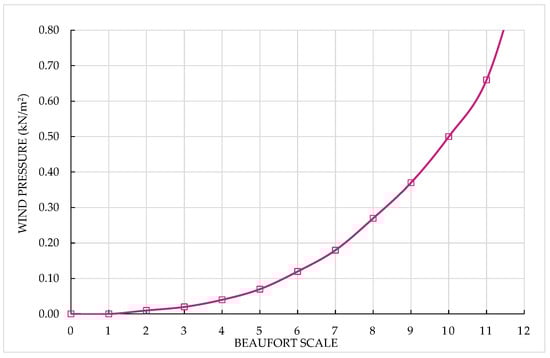
Figure 1.
Wind pressure (kN/m2) on the cargo items according to Beaufort scale calculations.
The sea-sloshing effect has remained unchanged and continues to be applicable in all situations, acting as an additional force on the cargo. It is calculated as exerting pressure up to a height of two (2) meters above the main deck or hatch covers, with a force of 1 kN/m2 applied on both the front and side surfaces.
3.3. Acceleration (Forces) on Cargo Calculation
In this paper, the longitudinal (fore–aft) and transverse (port–starboard) sliding movements were analyzed, as they represent the most common and critical types of cargo shifting. Tipping, which predominantly occurs in the longitudinal direction, is less frequent and typically applies only to cargo items with a significantly high center of gravity (CoG). Therefore, the total transverse and longitudinal sliding forces, according to the CSS Code, can be calculated as follows:
The first term in Equations (19) and (20) corresponds to the calculated transverse and longitudinal forces, which include wind and sea-sloshing pressures; the second term represents the transverse and longitudinal friction forces.
In these Equations aT and aL correspond to the calculated transverse and longitudinal accelerations; m is the cargo mass (mT); Ss2 is the side surface of cargo up to 2 m above deck (m2); SSF is the sea-sloshing shape factor; WSF is the wind shape factor; Sf2 is the front surface of cargo up to 2 m above deck (m2); μ is the friction coefficient; fz is the reduction factor of vertical force; and FZ is the vertical force.
The SSF (side shape factor) and WSF (wind shape factor) account for the shape of the cargo item—for example, a round pipe does not catch as much wind as a square box. According to the CSS Code, in the wind force calculations, Ss2 and Sf2 represent the total side and front surface areas of the cargo above deck (in m2), and these are not limited to the area up to 2 m above the deck.
3.4. Lashing and Securing Calculation
Since the securing arrangements to prevent cargo shifting consist of multiple lashing lines, which typically resist forces in more than one direction, it is necessary to calculate their capacity for each direction. These directions are defined by two angles: the vertical angle (α), which is the angle between the securing line and the horizontal plane, and the horizontal angle (β), which is the angle between the securing line and the transverse plane (port–starboard), as illustrated in Figure 2. The transverse sliding capacity (TSC) and the longitudinal sliding capacity (LSC) of the lashing lines can be calculated as follows:
where SF corresponds to the safety factor, which is 1.35 when using the alternative method of the CSS Code, and MSL is the maximum securing load of the devices. The relationship between MSL and SF defines the calculated strength (CS) of the securing devices, also referred to as the securing capacity.
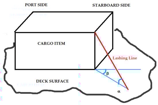
Figure 2.
Diagram of α and β angles of a lashing line (red color).
Once the angle formed by the lashing line in the vertical plane (α) and the height of the fixed lashing point on the cargo unit above the base (h) are known, the length of the lashing line (LLL) can be calculated as follows:
Then, the occupied area in the horizontal plane by the lashing line can be determined by the following expression:
It is relevant to mention that when a lashing device is working in a pure transverse direction, i.e., β = 0 (port–starboard), the calculated occupied area in m2 would be, theoretically, equal to 0.0 m2. However, the linear length (Llinear) in the horizontal plane (in linear meters) occupied by the lashing device, beyond the periphery of the cargo unit, can be calculated as follows:
In this paper, the adequacy of the lashing elements is evaluated by considering transverse and longitudinal sliding. Cargo shifting can be prevented if the sum of the lashing forces—based on their calculated strength according to the following methods—plus material friction exceeds the external forces, which are determined by the cargo’s weight, accelerations, sea sloshing, and wind pressure. Transverse and longitudinal tipping effects may be addressed in future studies.
3.5. Simulations’ Conditions: Case Study
For simulation purposes, the software Videck—Lashing and Securing was used (certificate no. RTS-STAT-213397). This SaaS-based solution is currently employed within the shipping industry and serves as the only graphical user interface approved by the classification society Lloyd’s Register for calculating acceleration forces as well as the required lashing and securing arrangements.
When a cargo unit is loaded onto a ship, it occupies a specific stowage position on board. If the vessel begins sailing without securing the cargo, the unit will start to move. Therefore, it is essential to secure the cargo to prevent shifting or even tipping. This securing involves fastening the cargo to structural parts of the vessel such as the tank top (cargo hold), weather deck, tween deck, or the vessel’s sides.
As the ship sails and encounters rough sea conditions, the cargo tends to slide towards the vessel’s lowest point due to sliding and uplift forces. To calculate these forces, it is necessary to know the speed and acceleration forces acting on the cargo, which depend on the cargo’s position on board, the ship’s loading condition expressed by the metacentric height (GM), and the cargo mass. The securing devices must have sufficient capacity to counteract the total force generated by all external and internal factors.
The coefficient of friction (μ) plays a key role in this force balance. It depends on the materials in contact between the cargo unit and the deck surface where it is stowed. According to the CSS Code, μ is 0.3 for steel-to-timber or steel-to-rubber contact, which is the most commonly used material type and the one employed in this study.
Regarding the ship’s particulars, the general cargo vessel described in Table 1 was selected, based on real data provided by a shipping company:

Table 1.
Ship’s particulars of the studied case.
The ship’s metacentric height (GM) depends on its loading condition and is usually obtained from an onboard stability program or estimated. According to the literature and empirical formulas [5,31], under normal operating conditions, the ship’s GM for the case studied here can be estimated between 1.10 m and 2.0 m. This range corresponds to a natural rolling period (Td) between 15.4 s and 11.4 s, which represents typical conditions on a merchant ship.
In general, a higher GM indicates greater ship stability. However, increased stability often results in a rougher motion, which in turn requires more robust lashing arrangements.
As shown in previous subsections, the acceleration and force calculation methods of the CSS Code and DNV 2024 standards involve different parameters, many of which are not directly comparable. To obtain valid and meaningful results, it is therefore necessary to simulate conditions common to both standards.
For this reason, the following parameters were selected and considered:
- Service Area Notation: R0, which corresponds to the least restrictive navigation area (covering winter, summer, and tropical conditions) according to the DNV 2024 standard. In the CSS Code, this is included in the basic acceleration data and represented by operations conducted worldwide throughout the entire year.
- Significant wave heights during the intended voyage: This corresponds to sailing under the least restrictive conditions from a reduction factor perspective (a reduction factor of 1.0 according to the CSS Code for the basic acceleration data). According to the CSS Code, a wave height of 12 m can be considered equivalent to the “harsh” conditions defined in the DNV calculations.
- Duration days: Between 7 and 30 days (DNV guidelines), this being the basic acceleration data of the CSS Code applicable to 25 navigation days.
Regarding the simulated cargo units, a full shipment of reels with the dimensions listed in Table 2 was selected.
Table 2.
Dimensions of the reels.
Regarding the selected cargo, it is assumed that the reels are properly secured to their footprints by the shipper; therefore, for practical purposes, the dimensions of the footprint and the projected area of the reels are considered the same.
This paper focuses on the tasks of stowage and lashing planners and ship personnel responsible for designing and executing appropriate stowage and securing plans. It is assumed that the cargo characteristics, weight, and locations of lashing points declared by the shippers are accurate, as ship staff have no control over these specific cargo details.
The proposed stowage plan for this shipment, developed using Videck software and illustrated in Figure 3, can be summarized as follows:
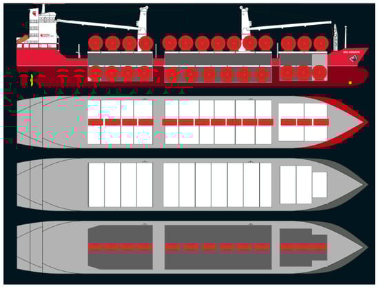
Figure 3.
Stowage plan of the reels.
- Vertically, one group of reels (tier) was stowed on deck, above the hatch cover panels, while a second group (tier) was stowed in the cargo holds (CH), on the tank top. The vertical positions of the center of gravity (VCoG) for the reels in these different sections are listed in Table 3.
Table 3. VCoG of the reels stowed in different ship sections.
Because of the height of the reels, it was not possible to stow an additional tier on the tween deck.
- 2.
- In the longitudinal direction, the entire length of the ship was fully loaded according to the cargo unit dimensions, as detailed in Table 4.
Table 4. Number of reels stowed in different ship sections.
As shown in the stowage plan in Figure 3 and summarized in Table 5, the longitudinal stowage positions are numbered from forward to aft, with position No. 1 representing the reel stowed at the foremost point and position No. 14 the rearmost reel on deck. For the reels stowed in the cargo holds, the aftmost position is No. 13. Table 5 also lists the longitudinal distances of the center of gravity (LCoG) for all stowage positions, measured from the aft perpendicular.
Table 5.
LCoG of the reels stowed in different ship sections from the aft perpendicular.
- 3.
- In the transverse direction, all reels were stowed along the ship’s centerline (transverse CoG: 0.00 m) since no significant differences in accelerations were observed when cargo units were placed closer to the ship’s sides.
Included in Figure 4 is the initial structured framework followed in this first stage of the present research.
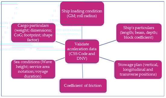
Figure 4.
Initial framework.
Considering the acceleration data calculated previously, the flowchart presented in Figure 5 outlines the new methodology developed to identify the optimal securing layout of lashing lines. This methodology ensures compliance with safety requirements across all possible ship stowage positions while minimizing the area occupied by the securing arrangement.
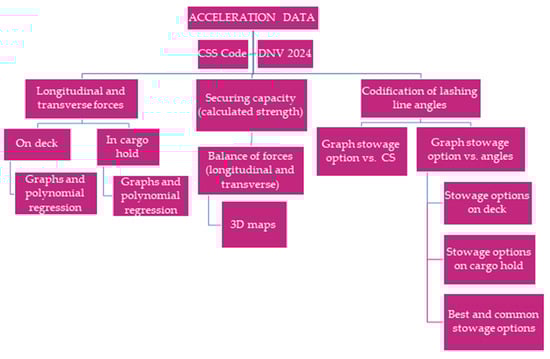
Figure 5.
Flowchart description.
4. Results and Discussion
4.1. Acceleration Comparison: CSS Code vs. DNV 2024
Figure 6 shows the vertical and longitudinal accelerations calculated according to the CSS Code and DNV 2024 for reels stowed on deck (a) and in the cargo hold (b). It can be observed that, for both methods, the longitudinal acceleration remains constant along the entire length of the ship, with the CSS Code predicting higher values than DNV 2024. Additionally, in both methods, the longitudinal acceleration on deck is approximately twice as high as in the cargo hold.
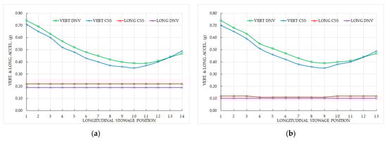
Figure 6.
Vertical and longitudinal accelerations as per the CSS Code and the DNV 2024. (a) Reels stowed on the main deck; (b) reels stowed in the cargo hold.
Regarding vertical acceleration, although the overall trend along the ship’s length is similar, the DNV 2024 values are generally higher than those of the CSS Code, except at the most aft stowage point. Vertical acceleration is significant because it affects transverse sliding—the most challenging movement to counteract, as it can occur simultaneously with longitudinal forces. These results hold true both on deck and in the cargo hold.
Moreover, simulating different ship loading conditions, expressed as GM, yields consistent longitudinal and vertical acceleration values. Therefore, from the perspective of these accelerations, the ship’s staff need not be concerned about the vessel’s final loading condition.
When calculating transverse accelerations with different GM values simulated, significant differences between the two calculation methods are observed along the longitudinal stowage positions. According to DNV 2024, the transverse acceleration experienced by cargo units on the main deck (Figure 7a) remains constant along the ship’s length, regardless of the GM value. In contrast, the CSS Code shows a similar overall trend but with notable variation: the highest acceleration occurs at the most forward point, and the lowest acceleration is near the midship section. Additionally, the acceleration at the forward end is higher than at the aft, indicating that, from a securing point of view, stowing cargo units towards the aft section is preferable.
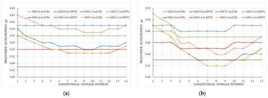
Figure 7.
Transverse acceleration as per the CSS Code and the DNV 2024 considering different GM values. (a) Reels stowed on the main deck; (b) reels stowed on the cargo hold.
Comparing both methods at the same GM value reveals differing patterns along the ship’s length. For example, at the lowest GM of 1.1 m (representing a ‘tender’ ship), transverse accelerations per DNV 2024 are significantly lower than those predicted by the CSS Code. However, at the higher GM of 2.0 m (a ‘stiff’ ship), the differences are less pronounced, and from roughly midship to aft, the acceleration requirements in DNV 2024 even exceed those of the CSS Code. A similar pattern is observed at GM = 1.7 m, with DNV 2024 demanding higher accelerations at most positions except the forward-most stowage.
When the reels are stowed in the cargo hold (Figure 7b), the trends and acceleration magnitudes differ notably from those on deck. According to DNV 2024, accelerations are not constant along the ship’s length—except at the lowest GM—due to variations in the tank top height of cargo holds 1 and 3 compared to hold 2. The CSS Code shows significant differences in accelerations between the extreme and central longitudinal positions. Comparing both methods for the same GM, similar trends to the deck stowage case are observed, with some positions showing higher accelerations per CSS Code and others per DNV 2024.
Therefore, from the perspective of transverse acceleration, neither method can be definitively classified as stricter or safer. This means that to select the safest method, the lashing planner or ship’s staff should carefully analyze each ship loading condition and longitudinal stowage position under both calculation methods.
If the ship has a high GM (referred to as ‘stiff’), it tends to be very rough in its motions, leading to higher acceleration forces and, consequently, requiring more lashing and securing devices. Conversely, if the ship has a low GM (‘tender’), its movements are milder, resulting in lower accelerations and less need for lashing and securing. However, it is important to consider that when the GM is very low, the natural rolling period is longer, which means the lashing lines are subjected to rolling motions for extended durations, repeatedly working as the ship rolls from one side to the other.
Since the main differences observed in the comparative study between the CSS Code and DNV 2024 are associated with transverse accelerations, a sensitivity analysis of the percentage error between both standards is included in Figure 8 for the cargo hold. In Figure 8a, the transverse acceleration is plotted as a function of the longitudinal stowage position, showing that the greatest deviations occur at the extreme positions (forward and aft). Figure 8b illustrates the variation in percentage error with respect to the GM values, revealing that the minimum discrepancies are observed at GM = 1.7 m.
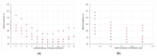
Figure 8.
Sensitivity analysis of the transverse accelerations comparing the results of both standards. (a) According to longitudinal stowage position; (b) According to ship’s loading condition.
4.2. Forces According to the Stowage Layout
Since neither calculation method proved consistently more stringent or safer across all conditions, this research chose the alternative method of the CSS Code for optimizing the stowage and lashing layout, as it is considered more reliable than the advanced method. Accordingly, a safety factor of 1.35 was applied. The ship’s loading condition was set at GM = 2.0 m (approximately Td = 11.4 s), representing an average for typical operating conditions.
Using the previously discussed simulation variables, the transverse and longitudinal sliding forces were calculated for all longitudinal stowage positions, both on deck and in the cargo hold.
Figure 9 shows the longitudinal (a) and transverse (b) forces experienced by the reels stowed at the 14 positions on the main deck. For the longitudinal forces (Figure 9a), a strong correlation with the stowage position was observed, with an R2 of 0.9917 using a second-degree polynomial regression. When the same regression was applied to the transverse forces (Figure 9b), the fit was less precise. Nevertheless, the magnitude of forces to be counteracted aligns with the results discussed in the previous subsection.
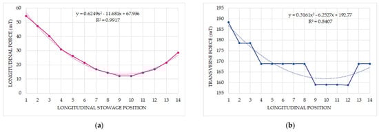
Figure 9.
Sustained forces by the reels stowed on deck along the ship’s length, showing the corresponding polynomial regression. (a) Longitudinal force; (b) transverse force.
When the same simulations were performed for the reels stowed in the 13 longitudinal positions within the cargo hold, notable differences in the magnitude of the forces sustained were observed. As shown in Figure 10a, the longitudinal forces are negative, indicating that no securing arrangements are necessary to counteract them. A high R2 value was achieved using a second-degree polynomial regression, demonstrating a strong fit. However, to prevent transverse sliding, as illustrated in Figure 10b, lashing is still required, although the forces to be counteracted are significantly lower compared to those for reels stowed on the main deck.
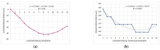
Figure 10.
Sustained forces by the reels stowed in the cargo hold along the ship’s length, showing the corresponding polynomial regression. (a) Longitudinal force; (b) transverse force.
4.3. Lashing and Securing Arrangement
Once it became evident that the most critical sliding to be counteracted is in the transverse direction—primarily due to the rolling motion—multiple simulations were performed under various conditions for the employed lashing elements.
The simulated securing devices were traditional lashing elements such as chains, wires, webbing, or synthetic lashings, which, once arranged, form vertical (α) and horizontal (β) angles relative to the ship’s planes. In our opinion, these are the types of securing devices where the expertise of a professional lashing planner and/or ship’s staff plays a crucial role, both economically and for safety, because their general layout can be adjusted. For this reason, plate stoppers or timber shoring were not included in the simulations. Note that when α = 0°, the lashing line is parallel to the horizontal plane; when β = 0°, the lashing line is oriented purely port–starboard, without any forward–aft component.
Regardless of the lashing material or whether the lines are new or used, the most important parameter is the maximum securing load (MSL), which is determined by the lowest MSL value among the different components making up the lashing line (e.g., D-ring, turnbuckle, and shackle). This MSL, combined with the safety factor, defines the calculated strength (CS), or securing capacity, of each lashing device. The total simulated CS can be the sum of capacities from multiple lashing lines or from a single device. Naturally, when multiple lashings are used, their arrangement angles (both α and β) must be consistent.
For each combination of α and β angles, and for each CS value, the longitudinal and transverse sliding capacities of the lashing lines were calculated. These capacities were then compared with the corresponding sustained forces, and any combinations that failed to meet the sliding force requirements in either direction were discarded.
As a representative example, Figure 11 shows, according to Equations (21) and (22), the transverse and longitudinal sliding capacities for a set of lashing lines with α = 50° and CS = 167 metric tons (mT), plotted against all β angles. When β = 90°, meaning the lashing works purely in the forward–aft direction, the maximum longitudinal capacity is achieved (145.4 mT), but it also generates a transverse capacity of 38.30 mT. Conversely, when β = 0°, i.e., with no deviation from the transverse direction, the same 38.30 mT capacity acts longitudinally, while the maximum transverse capacity (145.4 mT) is attained. From this graph, it can be inferred that β = 45° would be optimal for balancing maximum longitudinal and transverse components.
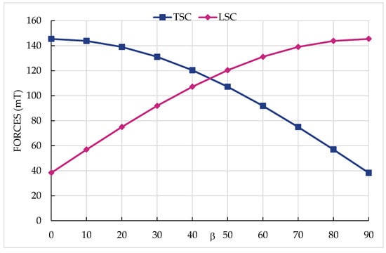
Figure 11.
Transverse sliding capacities (TSC) and longitudinal sliding capacities (LSC) for α = 50° and CS = 167 mT.
The same conclusion holds for different α angles and CS values. However, since the requirements for longitudinal and transverse directions differ significantly, this balanced optimum is less practical in reality. Therefore, the real objective is to find the best combination of angles and securing capacities that satisfies all sliding force requirements while minimizing the total lashing arrangement.
Figure 12 presents a representative example of the simulations performed using Videck software, where two chains operate with α = 50° and β = 50°. Both chains are oriented along the same longitudinal direction (either forward or aft), but they are secured to opposite sides of the vessel—one to port and the other to starboard.
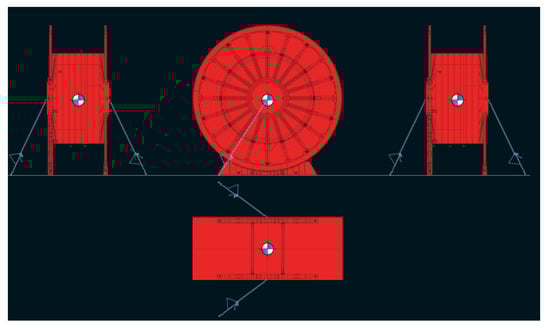
Figure 12.
Example of the lashing lines layout in a reel.
To ensure the safety of maritime transport of cargo units, both longitudinal and transverse sliding forces must be effectively balanced. Therefore, multiple simulations were conducted to determine the minimum securing capacity (CS) that satisfies both directional requirements simultaneously. Once the minimum CS was identified, additional simulations were performed by incrementally increasing the CS by 25–50 kN. Only the conditions where the lashing forces balanced both longitudinal and transverse external forces were considered valid.
As a representative example, Figure 13 shows a 3D plot illustrating the balance of forces for a reel stowed on deck at position No. 4. The plot depicts the difference between the external forces (weight, acceleration, wind pressure, and sea sloshing) and the securing forces generated by lashing devices with a CS of 222 kN.
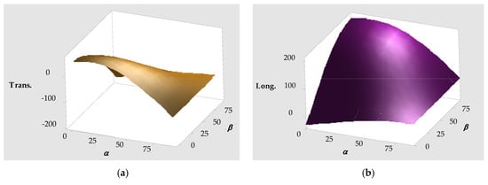
Figure 13.
Balance of forces for the reel stowed on deck in position nº 4, with a set of lashing lines of CS = 222 kN. (a) Transverse force; (b) longitudinal force.
For comparative purposes, Figure 14 shows the same conditions for a reel stowed in position No. 4, but this time in the cargo hold. The axes for the α and β angles have been adjusted to provide a different perspective. As observed in Figure 14a, the transverse balance often reaches positive values in many configurations, unlike the case when the reels were stowed on deck. In the longitudinal direction, the differences between the two stowage positions (on deck versus cargo hold) are less significant. Nonetheless, the shape and general trend of the longitudinal balance remain quite similar.
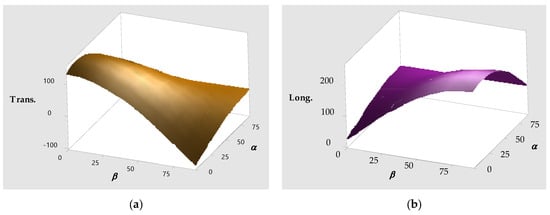
Figure 14.
Balance of forces for the reel stowed in cargo hold in position nº 4, with a set of lashing lines of CS = 222 kN. (a) Transverse force; (b) longitudinal force.
4.3.1. Cargo Units Stowed on Deck
To optimize the lashing arrangement, all possible combinations of angles (between α and β) were simulated for each analyzed CS. Given the large number of combinations, the codification system outlined in Table 6 was implemented in the calculation datasheet.
Table 6.
Codes for the combination of α and β angles.
As shown in Figure 15, across all possible combinations of the α and β angles for the 14 longitudinal stowage positions, the minimum CS required to satisfy both sliding force criteria was found to be 167 kN. Starting from this baseline, multiple simulations were carried out by incrementally increasing the CS by 25–50 kN up to 370 kN. Considering the 100 angle combinations from Table 6 and the 14 longitudinal positions, a total of 1400 simulations were performed for each CS value. From these simulations, the cases where the sliding forces were adequately counteracted were identified, revealing a strong correlation between CS and the number of valid stowage and securing layout options on deck, as illustrated in Figure 15.
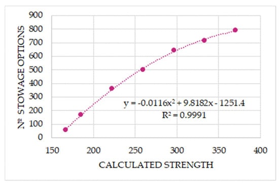
Figure 15.
Relationship between CS of the lashing lines and the proper stowage options when on deck.
Although the trend observed in Figure 15 is clear and the 2-degree polynomial fit shows high precision, the information provided is not particularly useful for lashing planners. Therefore, Figure 16 presents the number of proper stowage options that counteract sliding forces, plotted as a function of the α and β angles. Comparing the two figures reveals that the pattern and precision are more pronounced when analyzing the α angle (Figure 16b). However, the total number of proper stowage options is higher when considered as a function of the β angle—exceeding 600—compared to fewer than 500 options for α angles. This is a significant finding, suggesting that, in securing cargo, more attention should be given to the horizontal angle (β) of the lashing lines, as it allows for more flexible stowage options. Notably, most viable β angles cluster around medium values, and β angles above 60° should be avoided due to the lack of suitable securing options. Conversely, the only α angle with no valid securing option is the maximum angle of 90°, indicating that α angles generally offer more versatility in lashing design.
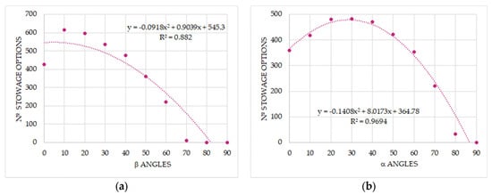
Figure 16.
(a) Number of stowage options on deck vs. horizontal angle (β); (b) number of stowage options on deck vs. vertical angle (α).
4.3.2. Cargo Units Stowed in Cargo Hold
In the simulations conducted for the 13 longitudinal stowage positions of the reels in the cargo hold, it was found—as shown in Figure 17—that the minimum calculated strength (CS) required to satisfy the sliding forces is 93 kN. This value is 74 kN lower than the minimum CS needed for the reels stowed on deck, as discussed in the previous subsection. Nevertheless, the precision of the trend remains nearly the same in both cases.
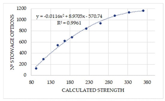
Figure 17.
Relationship between CS and the proper stowage options in cargo hold.
When the number of proper stowage options is analyzed in relation to the β and α angles, significant differences emerge compared to the simulations for cargo stowed on deck. As shown in Figure 18a, it is possible to satisfy the securing forces even when β = 90°. Similarly, Figure 18b demonstrates this is also true for α = 90°. These results indicate that the lashing area required would be minimal, thereby optimizing the number of cargo units that can be stowed within the same space.
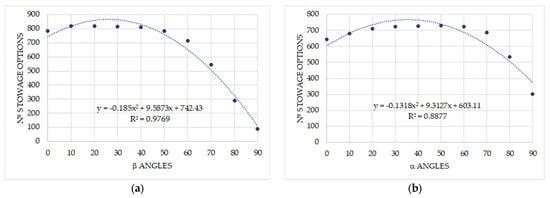
Figure 18.
(a) Number of stowage options in cargo hold vs. horizontal angle (β); (b) number of stowage options in cargo hold vs. vertical angle (α).
4.4. Optimal Lashing Layout
It was demonstrated that a significant number of angle combinations and securing capacities (CS) can satisfy the balance of sliding forces according to international standards (CSS Code), with notable differences depending on whether the cargo units (reels) are stowed on deck or in the cargo hold. However, while all these combinations may be safe for maritime transport, it is equally important during the stowage and lashing design phase to identify which angle combinations (α and β) result in the minimum occupied area. This optimization maximizes deck utilization for additional cargo units. In our view, this information is crucial as it allows for loading more cargo units within the same surface area (assuming permissible surface load margins are respected), ultimately benefiting ship owners and operators economically. Given the vital role of the stowage and lashing planner’s expertise in both safety and cost efficiency, it is necessary to represent the number of proper stowage options relative to the codified angle combinations. Table 7 presents these results for shipments stowed on deck, with the best 11 combinations—those offering more than 80 options—highlighted in dark green. For easier and faster interpretation, these results are also visually summarized in Figure 19.
Table 7.
Number of stowage options on deck for all angles’ combinations, where the intensity of green colour represent the largest number of stowage options, and the intensity of red colour, the lowest number of stowage options.
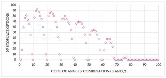
Figure 19.
Number of stowage options on deck vs. codification of angles’ combination.
Similarly, Table 8 presents the proper stowage options that allow for the safe securing of reels in the cargo hold based on the combinations of α and β angles. These results are also graphically illustrated in Figure 20. In this case, emphasis is placed on the top 11 combinations, each corresponding to more than 120 viable stowage options.
Table 8.
Number of stowage options in cargo hold for all angle combinations, where the intensity of green colour represent the largest number of stowage options, and the intensity of red colour, the lowest number of stowage options.
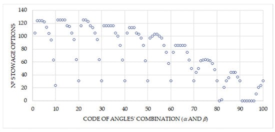
Figure 20.
Number of stowage options in cargo hold vs. codification of angles’ combination.
As shown in the data matrix of Figure 21, by analyzing the information derived from Table 7 and Table 8 and their corresponding graphs (Figure 19 and Figure 20), it was determined that the seven codes listed in Table 9 represent the best stowage options. These options simultaneously satisfy the requirements for stowage both on deck and in the cargo hold.
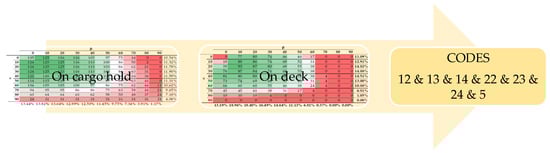
Figure 21.
Combination of data matrix and the result of the common codes.
Table 9.
Optimum lashing angle combinations.
To determine the lashing area occupied by the proposed securing layout, it is necessary to first calculate the length of the corresponding lashing lines using Equation (23). Although the α and β angles have been established from the previous results, it is essential to identify the height of the fixed lashing points on the cargo units above the bottom—information that must be provided by the shippers.
In the present study, considering the reel’s height of 6.00 m and a vertical offset of the center of gravity (VCoG) at 0.0 m, the fixed lashing points were initially simulated at 3.0 m above the reel’s bottom. Figure 22 presents a 3D map illustrating the occupied lashing area as a function of the relationship between the α and β angles for the seven optimal lashing options, applicable both on deck and in the cargo hold.
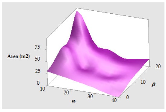
Figure 22.
Occupied area by the lashing lines according to the best combination between α and β angles.
When simulating different heights for the fixed lashing points on the reels, the shape and distribution of the 3D map remain consistent. The only difference observed is that as the height of the fixing point increases, the area occupied by the lashing device also becomes larger. Consequently, the maximum occupied area corresponds to code 22 (α = 10°; β = 20°), while the minimum area corresponds to code 14 (α = 30°; β = 10°). This is a significant finding, as it indicates that the optimal lashing arrangement for minimizing the occupied stowage area—thereby maximizing the number of cargo units loaded—is with lashing devices arranged at α = 30° and β = 10°.
Additionally, code 5 (α = 40°; β = 0°), which yields an occupied area of 0.0 m2 according to Equation (24), warrants special mention. This represents a unique case where the securing device acts purely in the transverse (port–starboard) direction, resulting in a theoretically zero occupied area. However, the length of linear meters occupied in the horizontal plane by the lashing line should instead be calculated using Equation (25), which for the present case results in the following:
In this case, it would not be possible to stow another cargo unit parallel to the first at a distance shorter than that calculated above using Equation (26). However, the lashing lines for these adjacent cargo units could still be secured to the vessel within the same area, provided they are fixed at the forward and aft ends of the lashing line.
5. Conclusions
This paper addresses the inherent challenge in maritime transport of optimizing cargo stowage and securing planning for non-standardized cargo, which is complicated by the heterogeneous sizes and types of such cargo. The expertise and optimized techniques of the stowage and lashing planner are crucial, as each non-standardized cargo item requires an individual securing calculation using appropriate securing methods and commonly available lashing equipment onboard, such as lashing lines.
The shipping industry widely relies on the IMO standard through the CSS Code, which is generally considered safer due to its higher safety factors. However, as demonstrated in this study, the output values from the CSS Code are not always more conservative than those from the DNV 2024 method. This highlights the need for a more detailed evaluation when choosing which securing standard to follow. The significance of these results lies in the fact that higher safety values imply more securing efforts, additional lashing lines, increased labor, and longer port times, all of which increase costs. If all parties agree, the lashing planner can select the desired safety level; however, if economic concerns over overlashing arise, calculations must be performed carefully and a reasonable safety margin should suffice. Hence, before starting the securing design, the lashing planner should be clear about the agreed safety level. The findings from the first part of this paper provide valuable insights to ship staff and lashing planners regarding the differences between key cargo securing standards to help avoid cargo losses and damages.
In the second part of this research, after extensive simulations, we identified seven optimal lashing layouts common to all stowage positions, enabling efficient and effective planning. These solutions apply along the ship’s length, both on deck and in cargo holds, regardless of ship particulars, loading conditions, or lashing equipment characteristics. Among these, the combination of α = 30° and β = 10° stands out as the best for minimizing deck space occupied—thus maximizing deck utilization for other cargo—while α = 10° and β = 20° corresponds to the arrangement occupying the maximum surface area.
Although qualified and experienced personnel should perform proper cargo stowage and securing planning, the results presented here are also accessible to less experienced users due to their clarity and ease of understanding. Therefore, this study offers a practical guide to meeting safety requirements for accelerations and forces while minimizing the occupied deck surface.
In the present investigation, unforeseen events commonly encountered during loading and lashing operations were not considered. In practical onboard scenarios, it is often challenging to implement a uniform cargo securing layout for the entire shipment across all stowage positions. Structural constraints and the ship’s geometry, particularly in the extreme positions (e.g., forward and aft), may prevent the lashing lines from being fixed at the positions suggested by the simulation results. Additionally, when cargo is stowed near the ship’s sides on deck, there may be insufficient space to achieve the recommended lashing angles.
Moreover, in this type of cargo transport, it is frequently necessary to perform welding operations to install D-rings or lashing plates as anchor points. However, in many cases, the presence of fuel tanks in the double bottom or structural joints between hatch cover panels may render welding prohibited or technically unfeasible, making it impossible to secure the cargo using the optimal lashing angles.
From another perspective, variable parameters such as the ship’s loading condition (GM) or navigational speed, which may fluctuate for various operational reasons during the voyage, can also affect the simulation outcomes. Consequently, the proposed methodology and the results obtained should be regarded as a general guideline, which must be adapted by the operator to account for the specific conditions and limitations encountered during actual sea transport.
Finally, although the simulations were performed using Videck—Lashing and Securing, a software solution approved by Lloyd’s Register, it is important to highlight that approval of the specific lashing arrangements and conditions is still required when implemented onboard the vessel.
Using a similar methodology to that employed in the present study, future research could extend the analysis to include the transverse and longitudinal tipping of large and tall cargo items. The objective would be to determine the optimal securing arrangements that satisfy all relevant force balance requirements, thereby enhancing both safety and cargo space efficiency.
Another promising line of future investigation would be the application of artificial intelligence (AI) techniques, similar to those already implemented in the containerized shipping sector, to enhance the planning and optimization of stowage and securing for non-standardized cargo.
Author Contributions
Conceptualization, J.M.P.-C., W.v.H., M.N.L.L. and J.A.O.; methodology, J.M.P.-C., W.v.H., M.N.L.L. and J.A.O.; software, J.M.P.-C., W.v.H., and J.A.O.; validation, J.M.P.-C., W.v.H., M.N.L.L. and J.A.O.; formal analysis, J.M.P.-C., W.v.H., M.N.L.L. and J.A.O.; investigation, J.M.P.-C., W.v.H., M.N.L.L. and J.A.O.; resources, J.M.P.-C., W.v.H., M.N.L.L. and J.A.O.; data curation, J.M.P.-C., W.v.H., M.N.L.L. and J.A.O.; writing—original draft preparation, J.M.P.-C., W.v.H., M.N.L.L. and J.A.O.; writing—review and editing, J.M.P.-C., W.v.H., M.N.L.L. and J.A.O.; visualization, J.M.P.-C., W.v.H., M.N.L.L. and J.A.O.; supervision, J.M.P.-C., W.v.H., M.N.L.L. and J.A.O. All authors have read and agreed to the published version of the manuscript.
Funding
This research received no external funding.
Data Availability Statement
The original contributions presented in the study are included in the article. Further inquiries can be directed to the corresponding author.
Conflicts of Interest
The author W.v.H. is the owner of Global Cargo Care & Videck, company owing the Videck software used in the research. The other authors declare no conflicts of interest.
Abbreviations
The following abbreviations are used in this manuscript:
| a0 | Acceleration parameter |
| aheave | Vertical acceleration |
| aL | Calculated longitudinal force |
| apitch | Pitch acceleration |
| aroll | Roll acceleration |
| aT | Calculated transverse force |
| B | Ship’s molded breadth |
| c1 | Correction factor for navigation area |
| c2 | Correction factor for season |
| c3 | Correction factor for navigation days |
| Cb | Block coefficient |
| CH | Cargo hold |
| CoG | Center of gravity |
| CS | Calculated strength (securing capacity) |
| CSF | Cargo shape factor |
| CSPP | Container Stowage Planning Problem |
| CSS | Code of Safe Practice for Cargo Stowage and Securing |
| fp | Coefficient for strength assessment |
| fz | Reduction factor of vertical force |
| FZ | Vertical force |
| g | Gravity acceleration |
| GM | Metacentric height |
| h | Height of the fixed lashing point in the cargo units |
| IMDG | International Maritime Dangerous Goods |
| IMO | International Maritime Organization |
| kr | Roll radius of gyration |
| L | Ship’s length |
| LCoG | Longitudinal distance of center of gravity from the aft perpendicular |
| Llinear | Length in the horizontal plane of the lashing line |
| LLL | Length of the lashing line |
| LSCs | Longitudinal sliding capacities of lashing lines |
| m | Cargo mass |
| MSL | Maximum securing load |
| SF | Safety factor |
| Sf2 | Front surface of cargo up to 2 m above deck |
| Ss2 | Side surface of cargo up to 2 m above deck |
| SSF | Sea-sloshing shape factor |
| Td | Natural rolling period |
| TSCs | Transverse sliding capacities of lashing lines |
| Tφ | Pitch period |
| Tθ | Roll period |
| v | Ship’s speed |
| VCoG | Vertical distance of center of gravity from the ship’s keel |
| WSF | Wind shape factor |
| x | Longitudinal distance from amidships to the cargo unit position |
| z | Vertical distance from the actual waterline to the cargo unit position |
| α | Vertical angle of the lashing line |
| β | Horizontal angle of the lashing line |
| φ | Pitch angle |
| μ | Friction coefficient |
| θ | Roll angle |
References
- European Maritime Safety Agency. Annual Overview of Marine Casualties and Incidents 2024. Available online: https://www.emsa.europa.eu/publications/reports/item/5352-annual-overview-of-marine-casualties-and-incidents-2024.html (accessed on 29 April 2025).
- Maceiras, C.; Cao-Feijóo, G.; Pérez-Canosa, J.M.; Orosa, J.A. Application of Machine Learning in the Identification and Prediction of Maritime Accident Factors. Appl. Sci. 2024, 14, 7239. [Google Scholar] [CrossRef]
- Li, M.; Wang, G.; Liu, K.; Lu, Y.; Wang, J. Experimental and Numerical Analysis of Supporting Forces and Lashing Forces in a Ship Cargo Securing Scheme. J. Mar. Sci. Eng. 2024, 12, 158. [Google Scholar] [CrossRef]
- International Maritime Organization (IMO). Code of Safe Practice for Cargo Stowage and Securing, 2021st ed.; Witherbys: Scotland, UK, 2021. [Google Scholar]
- DNV. Rules for Classification. Part 3, Chapter 4, Loads. 2024. Available online: https://rules.dnv.com/servicedocuments/dnvpm/ (accessed on 10 May 2025).
- Kabacinski, J.; Wisnicki, B. Accuracy analysis of stowing computations for securing non-standard cargoes on ships according to IMO CSS Code. Pol. Marit. Res. 2009, 16, 67–71. [Google Scholar] [CrossRef]
- Pérez-Canosa, J.M.; Orosa, J.A. A New Methodology for Optimization of Lashing Lines in the Securing Arrangement of Non-Standardized Cargo on Ships. Appl. Sci. 2024, 14, 11442. [Google Scholar] [CrossRef]
- Li, C.; Wang, D.; Cai, Z. Experimental and numerical investigation of lashing bridge and container stack dynamics using a scaled model test. Mar. Struct. 2021, 75, 102846. [Google Scholar] [CrossRef]
- Sun, X.; Wang, S.; Wang, Z.; Liu, C.; Yin, Y. A semi-automated approach to stowage planning for Ro-Ro ships. Ocean Eng. 2022, 247, 110648. [Google Scholar] [CrossRef]
- Nakamura, T.; Ota, S.; Nakajima, Y. Evaluation of expected maximum values of forces acting on container and lashing rods on a container ship. J. Mar. Sci. Technol. 2001, 6, 3–12. [Google Scholar] [CrossRef]
- Lee, C.; Lee, M.K.; Shin, J.Y. Lashing Force Prediction Model with Multimodal Deep Learning and AutoML for Stowage Planning Automation in Containerships. Logistics 2021, 5, 1. [Google Scholar] [CrossRef]
- Ovstebo, B.O.; Hvattum, L.M.; Fagerholt, K. Optimization of stowage plans for RoRo ships. Comput. Oper. Res. 2011, 38, 1425–1434. [Google Scholar] [CrossRef]
- Puisa, R. Optimal stowage on Ro-Ro decks for efficiency and safety. J. Mar. Eng. Technol. 2021, 20, 17–33. [Google Scholar] [CrossRef]
- Jia, B.; Fagerholt, K. Step-wise stowage planning of roll-on roll-off ships transporting dangerous goods. Marit. Transp. Res. 2021, 2, 100029. [Google Scholar] [CrossRef]
- Zhang, Z.; Lee, C.-Y. Multiobjective approaches for the ship stowage planning problem considering ship stability and container rehandles. IEE Trans. Syst. Man. Cybern. Syst. 2016, 46, 1374–1389. [Google Scholar] [CrossRef]
- Wang, Y.; Shi, G.; Hirayama, K. Many-Objective Container Stowage Optimization Based on Improved NSGA-III. J. Mar. Sci. Eng. 2022, 10, 517. [Google Scholar] [CrossRef]
- Bilican, M.S.; Karatas, M.; Zhen, Y.-J.; Turan, H.H.; Deveci, M. A survey of shipping line Container Stowage Planning problems. Expert Syst. Appl. 2024, 255, 124408. [Google Scholar] [CrossRef]
- Van Twiller, J.; Sivertsen, A.; Pacino, D.; Jense, R.M. Literature survey on the container stowage planning problem. Eur. J. Oper. Res. 2024, 317, 841–857. [Google Scholar] [CrossRef]
- Cho, J.; Ku, N. Developing a Container Ship Loading-Planning Program Using Reinforcement Learning. J. Mar. Sci. Eng. 2024, 12, 1832. [Google Scholar] [CrossRef]
- Gao, Y.; Zhen, L. A decision framework for decomposed stowage planning for containers. Transp. Res. E Logist. Transp. Rev. 2024, 183, 103420. [Google Scholar] [CrossRef]
- Huang, P.; Wang, Y.; Zhang, P. Collaborative Optimization of Vessel Stowage Planning and Yard Pickup in Automated Container Terminals. Mathematics 2024, 12, 3387. [Google Scholar] [CrossRef]
- Zhang, D.; Qu, Z.; Wang, W.; Yu, J.; Yang, Z. New uncertainty modelling for cargo stowage plans of general cargo ships. Transp. Res. E Logist. Transp. Rev. 2020, 144, 102151. [Google Scholar] [CrossRef]
- Radisic, Z. Necessity of proper lashing of containers on the ship’s deck as part of optimization of the sea voyage. Promet-Traffic Transp. 2004, 16, 97–104. [Google Scholar]
- Sternsson, M.; Björkenstam, U. Statistical study of lashing forces measured on-board a PCTC vessel. Mar. Struct. 2003, 16, 345–354. [Google Scholar] [CrossRef]
- Shigunov, V.; El Moctar, O.; Rathje, H. Operational Guidance for Prevention of Cargo Loss and Damage on Container Ships. Sh. Technol. Res. 2010, 57, 8–25. [Google Scholar] [CrossRef]
- Pérez-Canosa, J.M.; Orosa, J.A. Proposal of a New Control System Making Use of AI Tools to Predict a Ship’s Behaviour When Approaching the Synchronism Phenomenon. Appl. Sci. 2024, 14, 4517. [Google Scholar] [CrossRef]
- Nam, W.; Park, S.-J.; Kim, K. Numerical Investigation of the Ultimate Strength of D-Ring Devices and Deck Structures. J. Mar. Sci. Eng. 2022, 10, 952. [Google Scholar] [CrossRef]
- Chepok, A.O. Determination of inertia forces acting on break bulk cargo on route. TransNav. Int. J. Mar. Navig. Saf. Sea Transp. 2023, 7, 477–479. [Google Scholar] [CrossRef][Green Version]
- Pérez-Canosa, J.M.; Iglesias-Baniela, S.; Salgado-Don, A. The Limitations on the Use of the IMO CSS Code in Project Cargo—Case Study: Grillage Design for the Sea Transport of Gas Slug Catchers. Appl. Mech. 2020, 1, 123–141. [Google Scholar] [CrossRef]
- Bergmann, J. Focus on the Cargo and Sustainability: Trends in the Heavy-Lift Segment. Available online: https://www.dnv.com/expert-story/maritime-impact/focus-on-the-cargo-and-sustainability-trends-in-the-heavy-lift-segment/ (accessed on 12 June 2025).
- Bonilla de la Corte, A. Ship’s Theory, 4th ed.; Librería San José: Vigo, Spain, 1994. [Google Scholar]
Disclaimer/Publisher’s Note: The statements, opinions and data contained in all publications are solely those of the individual author(s) and contributor(s) and not of MDPI and/or the editor(s). MDPI and/or the editor(s) disclaim responsibility for any injury to people or property resulting from any ideas, methods, instructions or products referred to in the content. |
© 2025 by the authors. Licensee MDPI, Basel, Switzerland. This article is an open access article distributed under the terms and conditions of the Creative Commons Attribution (CC BY) license (https://creativecommons.org/licenses/by/4.0/).