
Implant-Supported Prostheses in the Edentulous Mandible: Biomechanical Analysis of Different Implant Configurations via Finite Element Analysis


Abstract

1. Introduction
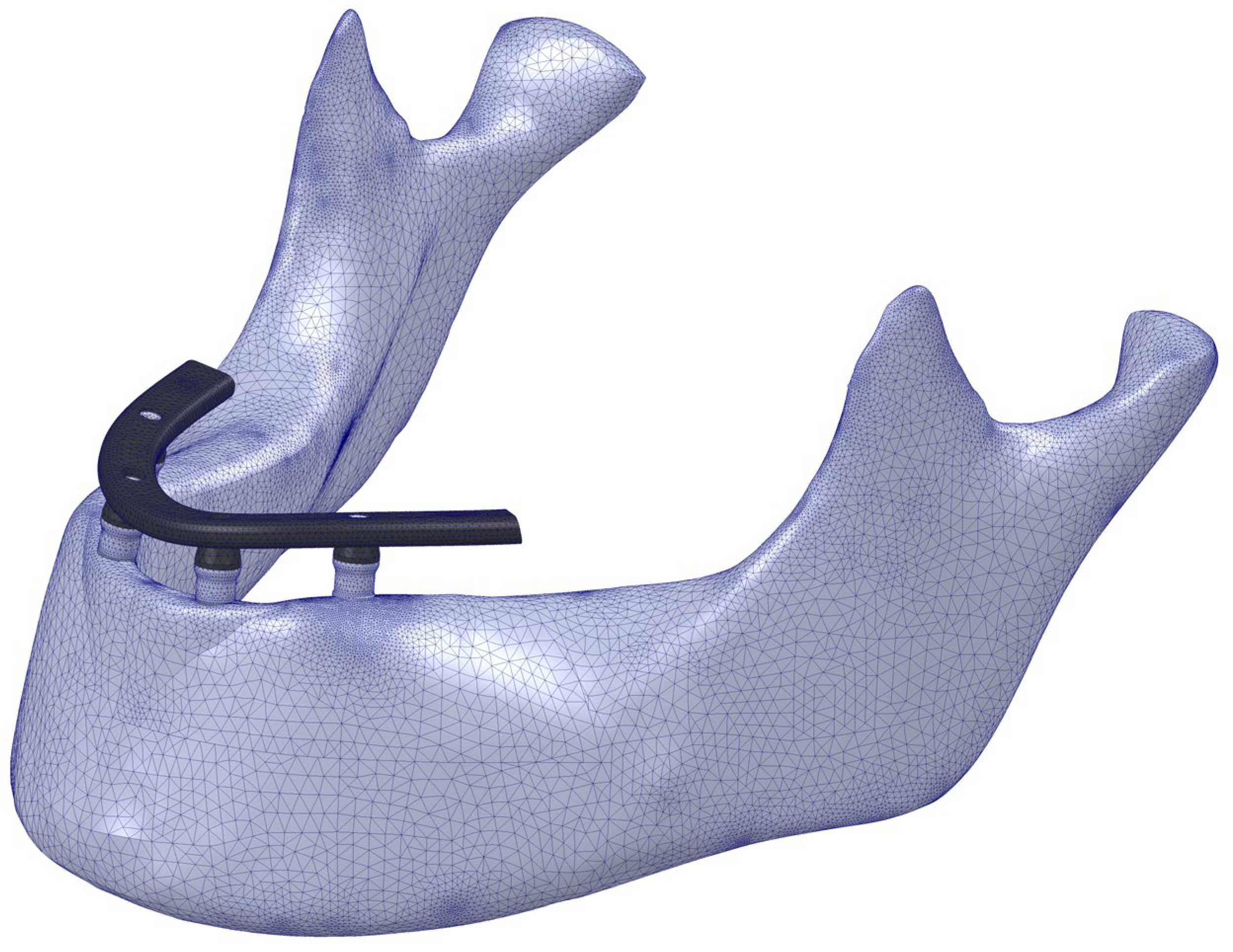
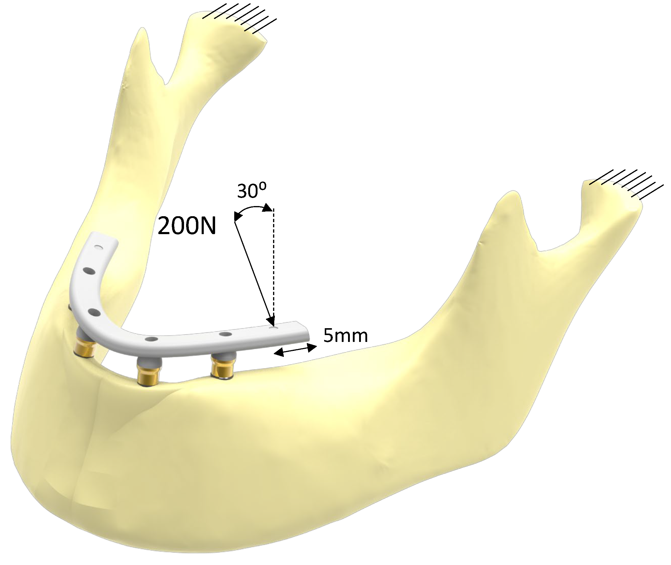
2. Materials and Methods

| Component | Material | Elastic Modulus (MPa) | Poisson Coef. |
|---|---|---|---|
| Dental implant | Pure titanium [46] | 105,000 | 0.37 |
| Superstructure retaining screw | Titanium alloy [46] | 113,800 | 0.342 |
| Transepithelial body | Pure titanium [46] | 105,000 | 0.37 |
| Transepithelial screw | Titanium alloy [46] | 113,800 | 0.342 |
| Prostheses | CrCo alloy [47] | 218,000 | 0.33 |
| Bone | Cortical bone [47] | 13,700 | 0.28 |
| Trabecular bone [47] | 1370 | 0.3 |
3. Results
4. Discussion
5. Conclusions
- -
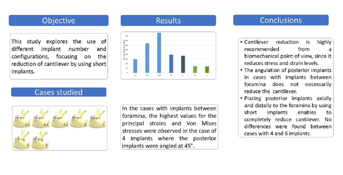
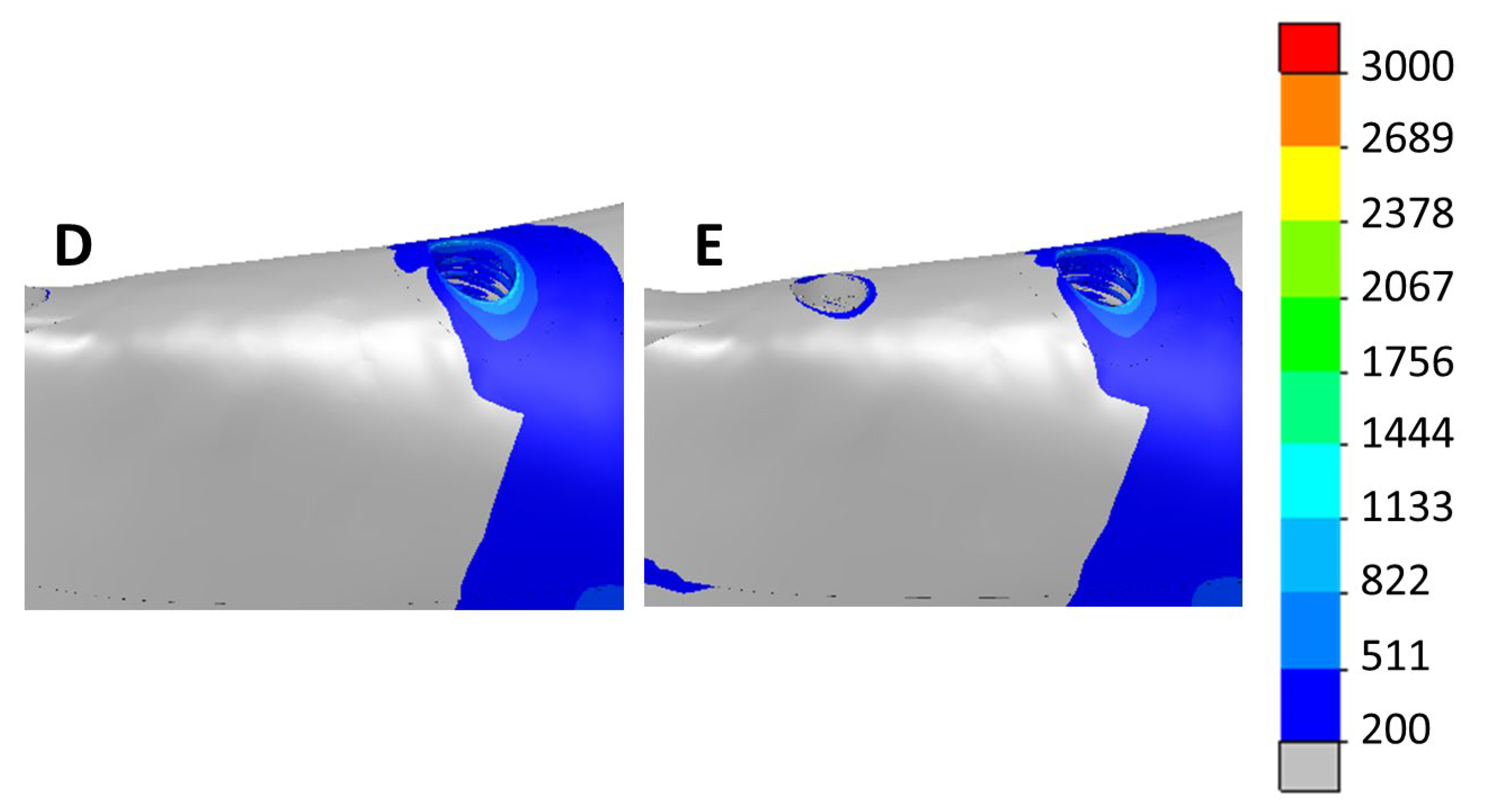
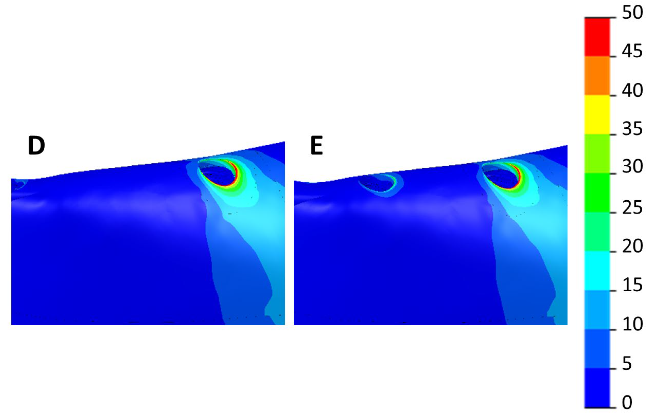
- From a biomechanical point of view, cases with posterior implants placed distally to the foramen were demonstrated to be the best options to reduce cantilevers.
- -
- The angulation of posterior implants in cases with implants between the foramina does not necessarily reduce the prosthetic cantilever.
- -
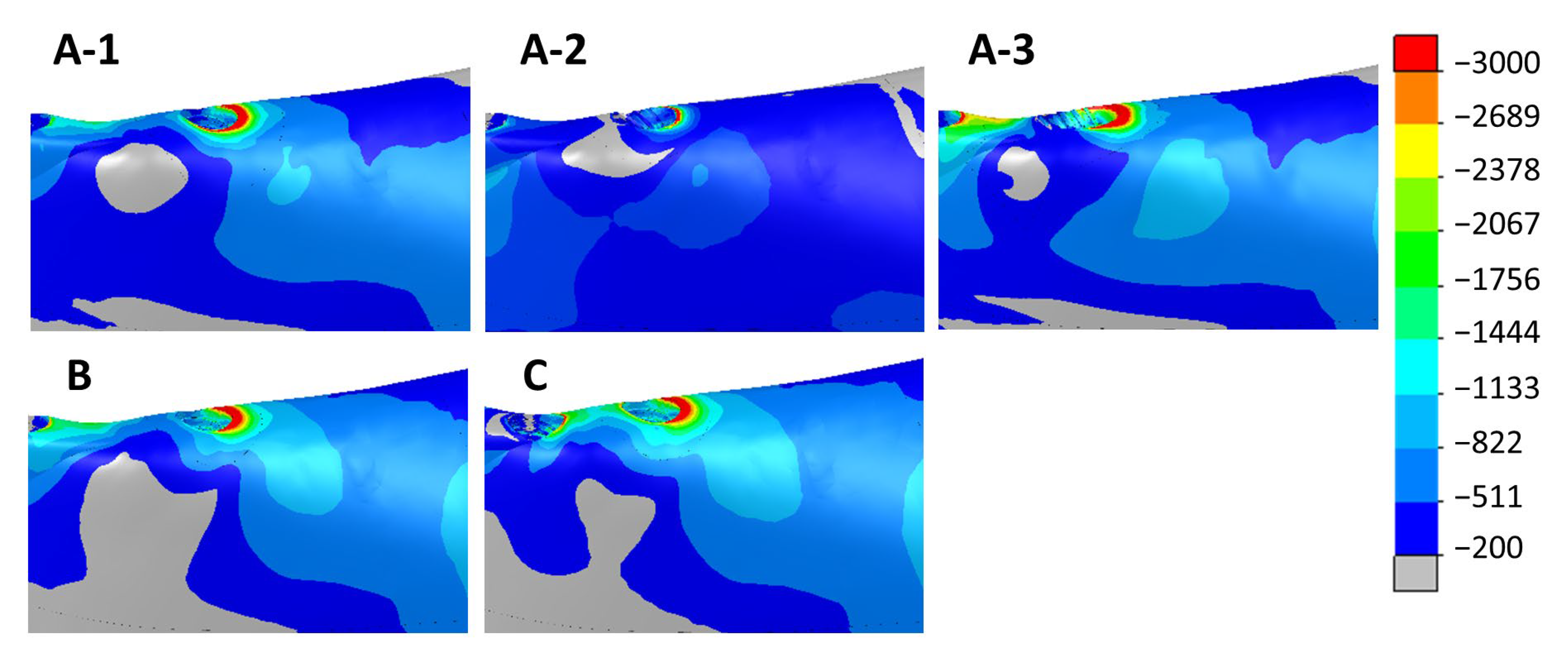
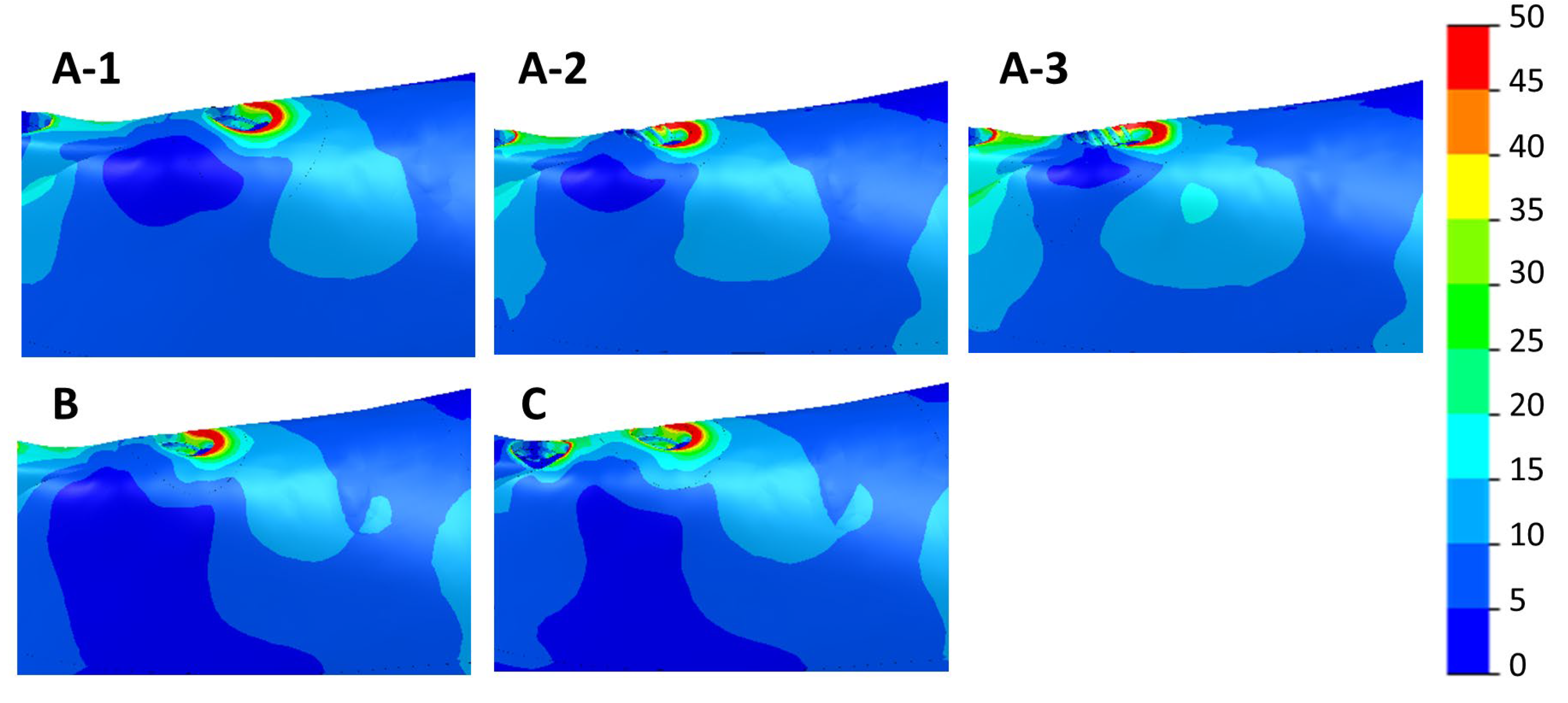
- Tilting posterior implants may cause a significant increase in the stresses and strains at the implant–bone interface.
- -
- No significant differences in bone principal strain and stress were observed for scenarios with four or six implants with the two posterior implants located distally to the foramina.
- -
- Tilting posterior implants at 45° demonstrated to be the worst scenario, showing a dramatic increase in stresses and strains.
Author Contributions
Funding
Institutional Review Board Statement
Informed Consent Statement
Data Availability Statement
Conflicts of Interest
References
- Adell, R. A 15-Year Study of Osseointegrated Implants in the Treatment of the Edentulous Jaw. Int. J. Oral Surg. 1981, 10, 387–416. [Google Scholar] [CrossRef] [PubMed]
- Jivraj, S.; Chee, W. Treatment Planning of Implants in Posterior Quadrants. Br. Dent. J. 2006, 201, 13–23. [Google Scholar] [CrossRef]
- Esposito, M.; Grusovin, M.G.; Felice, P.; Karatzopoulos, G.; Worthington, H.V.; Coulthard, P. Interventions for Replacing Missing Teeth: Horizontal and Vertical Bone Augmentation Techniques for Dental Implant Treatment. Cochrane Database Syst. Rev. 2009, 2009, CD003607. [Google Scholar] [CrossRef] [PubMed]
- Maló, P.; Rangert, B.; Nobre, M. “All-on-Four” Immediate-Function Concept with Brånemark System® Implants for Completely Edentulous Mandibles: A Retrospective Clinical Study. Clin. Implant Dent. Relat. Res. 2003, 5, 2–9. [Google Scholar] [CrossRef] [PubMed]
- Carossa, M.; Alovisi, M.; Crupi, A.; Ambrogio, G.; Pera, F. Full-Arch Rehabilitation Using Trans-Mucosal Tissue-Level Implants with and without Implant-Abutment Units: A Case Report. Dent. J. 2022, 10, 116. [Google Scholar] [CrossRef] [PubMed]
- Catapano, S.; Ferrari, M.; Mobilio, N.; Montanari, M.; Corsalini, M.; Grande, F. Comparative Analysis of the Stability of Prosthetic Screws under Cyclic Loading in Implant Prosthodontics: An In Vitro Study. Appl. Sci. 2021, 11, 622. [Google Scholar] [CrossRef]
- Bedrossian, E.; Bedrossian, E. Treatment Planning the Edentulous Mandible. Review of Biomechanical and Clinical Considerations: An Update. Int. J. Oral Maxillofac. Implant. 2019, 34, e33–e41. [Google Scholar] [CrossRef]
- Nedir, R.; Bischof, M.; Briaux, J.M.; Beyer, S.; Szmukler-Monder, S.; Bernard, J.P. A 7-Year Life Table Analysis from a Prospective Study on ITI Implants with Special Emphasis on the Use of Short Implants. Results from a Private Practice. Clin. Oral Implant. Res. 2004, 15, 150–157. [Google Scholar] [CrossRef]
- Anitua, E.; Orive, G.; Aguirre, J.J.; Andía, I. Five-Year Clinical Evaluation of Short Dental Implants Placed in Posterior Areas: A Retrospective Study. J. Periodontol. 2008, 79, 42–48. [Google Scholar] [CrossRef]
- Menini, M.; Pesce, P.; Delucchi, F.; Ambrogio, G.; Canepa, C.; Carossa, M.; Pera, F. One-stage versus Two-stage Technique Using Two Splinted Extra-short Implants: A Multicentric Split-mouth Study with a One-year Follow-up. Clin. Implant Dent. Relat. Res. 2022, 24, 602–610. [Google Scholar] [CrossRef]
- Anitua, E.; Alkhraisat, M.H. Fifteen-Year Follow-up of Short Dental Implants in the Completely Edentulous Jaw: Submerged Versus Nonsubmerged Healing. Implant Dent. 2019, 28, 551–555. [Google Scholar] [CrossRef] [PubMed]
- Horiuchi, K.; Uchida, H.; Yamamoto, K.; Sugimura, M. Immediate Loading of Branemark System Implants Following Placement in Edentulous Patients: A Clinical Report. Int. J. Oral Maxillofac. Implant. 2000, 15, 824–830. [Google Scholar]
- Chiapasco, M.; Abati, S.; Romeo, E.; Vogel, G. Implant-Retained Mandibular Overdentures with Branemark System MKII Implants: A Prospective Comparative Study between Delayed and Immediate Loading. Int. J. Oral Maxillofac. Implant. 2001, 16, 537–546. [Google Scholar]
- Bakaeen, L.G.; Winkler, S.; Neff, P.A. The Effect of Implant Diameter, Restoration Design, and Occlusal Table Variations on Screw Loosening of Posterior Single-Tooth Implant Restorations. J. Oral Implantol. 2001, 17, 63–72. [Google Scholar] [CrossRef]
- Winkler, S.; Morris, H.F.; Ochi, S. Implant Survival to 36 Months as Related to Length and Diameter. Ann. Periodontol./Am. Acad. Periodontol. 2000, 5, 22–31. [Google Scholar] [CrossRef] [PubMed]
- Wyatt, C.; Zarb, G. Treatment Outcomes of Patients with Implant-Supported Fixed Partial Prostheses. Int. J. Oral Maxillofac. Implant. 1998, 13, 204–211. [Google Scholar]
- Anitua, E.; Piñas, L.; Orive, G. Retrospective Study of Short and Extra-Short Implants Placed in Posterior Regions: Influence of Crown-to-Implant Ratio on Marginal Bone Loss. Clin. Implant Dent. Relat. Res. 2015, 17, 102–110. [Google Scholar] [CrossRef]
- Anitua, E.; Piñas, L.; Begoña, L.; Orive, G. Long-Term Retrospective Evaluation of Short Implants in the Posterior Areas: Clinical Results after 10–12 Years. J. Clin. Periodontol. 2014, 41, 404–411. [Google Scholar] [CrossRef]
- Anitua, E.; Orive, G. Short Implants in Maxillae and Mandibles: A Retrospective Study with 1 to 8 Years of Follow-Up. J. Periodontol. 2010, 81, 819–826. [Google Scholar] [CrossRef]
- Anitua, E.; Alkhraisat, M.H. 15-Year Follow-up of Short Dental Implants Placed in the Partially Edentulous Patient: Mandible Vs Maxilla. Ann. Anat. 2019, 222, 88–93. [Google Scholar] [CrossRef]
- Himmlová, L.; Dostálová, T.; Kácovský, A.; Konvičková, S. Influence of Implant Length and Diameter on Stress Distribution: A Finite Element Analysis. J. Prosthet. Dent. 2004, 91, 20–25. [Google Scholar] [CrossRef] [PubMed]
- Topkaya, H.; Kaman, M.O. Effect of Dental Implant Dimensions on Fatigue Behaviour: A Numerical Approach. Uludag Univ. J. Fac. Eng. 2018, 23, 249–260. [Google Scholar] [CrossRef]
- Lee, J.H.; Frias, V.; Lee, K.W.; Wright, R.F. Effect of Implant Size and Shape on Implant Success Rates: A Literature Review. J. Prosthet. Dent. 2005, 94, 377–381. [Google Scholar] [CrossRef] [PubMed]
- Anitua, E.; Tapia, R.; Luzuriaga, F.; Orive, G. Influence of Implant Length, Diameter, and Geometry on Stress Distribution: A Finite Element Analysis. Int. J. Periodontics Restor. Dent. 2010, 30, 89–95. [Google Scholar] [CrossRef]
- Georgiopoulos, B.; Kalioras, K.; Provatidis, C.; Manda, M.; Koidis, P. The Effects of Implant Length and Diameter Prior to and after Osseointegration: A 2-D Finite Element Analysis. J. Oral Implantol. 2007, 33, 243–256. [Google Scholar] [CrossRef]
- Baggi, L.; Cappelloni, I.; di Girolamo, M.; Maceri, F.; Vairo, G. The Influence of Implant Diameter and Length on Stress Distribution of Osseointegrated Implants Related to Crestal Bone Geometry: A Three-Dimensional Finite Element Analysis. J. Prosthet. Dent. 2008, 100, 422–431. [Google Scholar] [CrossRef]
- Lum, L.B. A Biomechanical Rationale for the Use of Short Implants. J. Oral Implantol. 1991, 17, 126–131. [Google Scholar]
- Hingsammer, L.; Pommer, B.; Hunger, S.; Stehrer, R.; Watzek, G.; Insua, A. Influence of Implant Length and Associated Parameters upon Biomechanical Forces in Finite Element Analyses: A Systematic Review. Implant Dent. 2019, 28, 296–305. [Google Scholar] [CrossRef]
- Fazi, G.; Tellini, S.; Vangi, D.; Branchi, R. Three-Dimensional Finite Element Analysis of Different Implant Configurations for a Mandibular Fixed Prosthesis. Int. J. Oral Maxillofac. Implant. 2011, 26, 752–759. [Google Scholar]
- Brunski, J.B. Biomechanical Aspects of the Optimal Number of Implants to Carry a Cross-Arch Full Restoration. Eur. J. Oral Implantol. 2014, 7 (Suppl. S2), S111–S131. [Google Scholar]
- Özdemir Doǧan, D.; Polat, N.T.; Polat, S.; Şeker, E.; Gül, E.B. Evaluation of “All-on-Four” Concept and Alternative Designs with 3D Finite Element Analysis Method. Clin. Implant Dent. Relat. Res. 2014, 16, 501–510. [Google Scholar] [CrossRef] [PubMed]
- Doganay, O.; Kilic, E. Comparative Finite Element Analysis of Short Implants with Different Treatment Approaches in the Atrophic Mandible. Int. J. Oral Maxillofac. Implant. 2020, 35, e69–e76. [Google Scholar] [CrossRef] [PubMed]
- Bozyel, D.; Faruk, S.T. Biomechanical Behavior of All-on-4 and M-4 Configurations in an Atrophic Maxilla: A 3D Finite Element Method. Med. Sci. Monit. 2021, 27, e929908. [Google Scholar] [CrossRef]
- Horita, S.; Sugiura, T.; Yamamoto, K.; Murakami, K.; Imai, Y.; Kirita, T. Biomechanical Analysis of Immediately Loaded Implants According to the “All-on-Four” Concept. J. Prosthodont. Res. 2017, 61, 123–132. [Google Scholar] [CrossRef] [PubMed]
- Liu, T.; Mu, Z.; Yu, T.; Wang, C.; Huang, Y. Biomechanical Comparison of Implant Inclinations and Load Times with the All-on-4 Treatment Concept: A Three-Dimensional Finite Element Analysis. Comput. Methods Biomech. Biomed. Eng. 2019, 22, 585–594. [Google Scholar] [CrossRef]
- Sugiura, T.; Yamamoto, K.; Horita, S.; Murakami, K.; Kirita, T. Micromotion Analysis of Different Implant Configuration, Bone Density, and Crestal Cortical Bone Thickness in Immediately Loaded Mandibular Full-Arch Implant Restorations: A Nonlinear Finite Element Study. Clin. Implant Dent. Relat. Res. 2018, 20, 43–49. [Google Scholar] [CrossRef]
- Almeida, E.O.; Rocha, E.P.; Freitas Júnior, A.C.; Anchieta, R.B.; Poveda, R.; Gupta, N.; Coelho, P.G. Tilted and Short Implants Supporting Fixed Prosthesis in an Atrophic Maxilla: A 3D-FEA Biomechanical Evaluation. Clin. Implant Dent. Relat. Res. 2015, 17, e332–e342. [Google Scholar] [CrossRef]
- Irving, J.T. Factors Concerning Bone Loss Associated with Periodontal Disease. J. Dent. Res. 1970, 49, 262–267. [Google Scholar] [CrossRef]
- Kelkar, K.; Bhat, V.; Hegde, C. Finite Element Analysis of the Effect of Framework Materials at the Bone-Implant Interface in the All-on-Four Implant System. Dent. Res. J. 2021, 18, 1. [Google Scholar] [CrossRef]
- Dayan, S.C.; Geckili, O. The Influence of Framework Material on Stress Distribution in Maxillary Complete-Arch Fixed Prostheses Supported by Four Dental Implants: A Three-Dimensional Finite Element Analysis. Comput. Methods Biomech. Biomed. Eng. 2021, 24, 1606–1617. [Google Scholar] [CrossRef]
- Grande, F.; Pozzan, M.C.; Marconato, R.; Mollica, F.; Catapano, S. Evaluation of Load Distribution in a Mandibular Model with Four Implants Depending on the Number of Prosthetic Screws Used for OT-Bridge System: A Finite Element Analysis (FEA). Materials 2022, 15, 7963. [Google Scholar] [CrossRef] [PubMed]
- Tribst, J.P.M.; de Morais, D.C.; de Matos, J.D.M.; Lopes, G.d.R.S.; Dal Piva, A.M.d.O.; Borges, A.L.S.; Bottino, M.A.; Lanzotti, A.; Martorelli, M.; Ausiello, P. Influence of Framework Material and Posterior Implant Angulation in Full-Arch All-on-4 Implant-Supported Prosthesis Stress Concentration. Dent. J. 2022, 10, 12. [Google Scholar] [CrossRef] [PubMed]
- Gümrükçü, Z.; Korkmaz, Y.T. Influence of Implant Number, Length, and Tilting Degree on Stress Distribution in Atrophic Maxilla: A Finite Element Study. Med. Biol. Eng. Comput. 2018, 56, 979–989. [Google Scholar] [CrossRef] [PubMed]
- Ozan, O.; Kurtulmus-Yilmaz, S. Biomechanical Comparison of Different Implant Inclinations and Cantilever Lengths in All-on-4 Treatment Concept by Three-Dimensional Finite Element Analysis. Int. J. Oral Maxillofac. Implant. 2018, 33, 64–71. [Google Scholar] [CrossRef] [PubMed]
- Sato, Y.; Teixeira, E.R.; Tsuga, K.; Shindoi, N. The Effectiveness of a New Algorithm on a Three-Dimensional Finite Element Model Construction of Bone Trabeculae in Implant Biomechanics. J. Oral Rehabil. 1999, 26, 640–643. [Google Scholar] [CrossRef]
- Moreira de Melo, E.J.; Francischone, C.E. Three-Dimensional Finite Element Analysis of Two Angled Narrow-Diameter Implant Designs for an All-on-4 Prosthesis. J. Prosthet. Dent. 2020, 124, 477–484. [Google Scholar] [CrossRef]
- Capatti, R.; Barboza, M.; Antunes, A.; Oliveira, D.; Seraidarian, P. Viability of Maxillary Single Crowns Supported by 4-Mm Short Implants: A Finite Element Study. Int. J. Oral Maxillofac. Implant. 2020, 35, e41–e50. [Google Scholar] [CrossRef]
- Frost, H.M. The Utah Paradigm of Skeletal Physiology; International Society of Musculoskeletal and Neuronal Interactions (ISMNI): Athens, Greece, 2004; Volume I. [Google Scholar]
- Frost, H.M. A 2003 Update of Bone Physiology and Wolff s Law for Clinicians. Angle Orthod. 2004, 74, 3–15. [Google Scholar]
- Frost, H.M. Perspectives: Bone’s Mechanical Usage Windows. Bone Min. 1992, 19, 257–271. [Google Scholar] [CrossRef]
- Bhering, C.L.B.; Mesquita, M.F.; Kemmoku, D.T.; Noritomi, P.Y.; Consani, R.L.X.; Barão, V.A.R. Comparison between All-on-Four and All-on-Six Treatment Concepts and Framework Material on Stress Distribution in Atrophic Maxilla: A Prototyping Guided 3D-FEA Study. Mater. Sci. Eng. C 2016, 69, 715–725. [Google Scholar] [CrossRef]
- Anitua, E. The Biomechanics of the Short Implant. In Short and Extra-Short Implants; Team Work Media: Madrid, Spain, 2017. [Google Scholar]
- Anitua, E. Surgical Manual. Oral Implantology; Team Work Media: Madrid, Spain, 2013; ISBN 8487673283. [Google Scholar]
- Anitua, E. Predictable Prosthesis on Implants. Key Points and Techniques, 1st ed.; Team Work Media: Madrid, Spain, 2018; ISBN 9788487673573. [Google Scholar]
- Krekmanov, L.; Kahn, M.; Rangert, B.; Lindström, H. Tilting of Posterior Mandibular and Maxillary Implants for Improved Prosthesis Support. Int. J. Oral Maxillofac. Implant. 2000, 15, 405–414. [Google Scholar]
- Takahashi, T.; Shimamura, I.; Sakurai, K. Influence of Number and Inclination Angle of Implants on Stress Distribution in Mandibular Cortical Bone with All-on-4 Concept. J. Prosthodont. Res. 2010, 54, 179–184. [Google Scholar] [CrossRef] [PubMed]


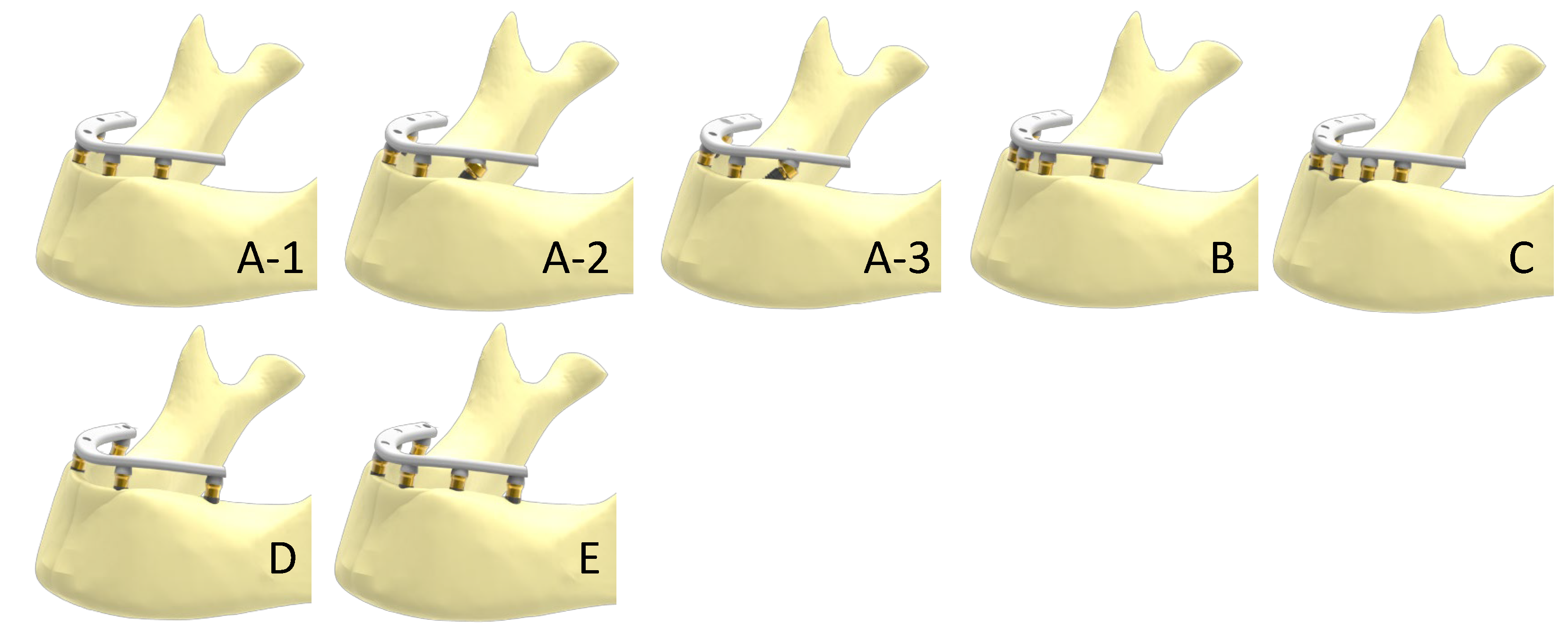
| Scenario | Implants (n) | Implant Position | Implant Angulation | Cantilever Length (mm) |
|---|---|---|---|---|
| A-1 | 4 | 2–Lateral incisor | Axial | 11.5 |
| 2–Second premolar | ||||
| A-2 | 4 | 2–Lateral incisor | Axial | 11.5 |
| 2–Second premolar | 30° distally tilted | |||
| A-3 | 4 | 2–Lateral incisor | Axial | 11.5 |
| 2–Second premolar | 45° distally tilted | |||
| B | 5 | 1–Between central incisors | Axial | 11.5 |
| 2–Lateral incisor | ||||
| 2–Second premolar | ||||
| C | 6 | 2–Central incisor | Axial | 11.5 |
| 2–Canine | ||||
| 2–Second premolar | ||||
| D | 4 | 2–Canine | Axial | 0 |
| 2–Second molar | ||||
| E | 6 | 2–Lateral incisor | Axial | 0 |
| 2–Second premolar | ||||
| 2–Second molar |
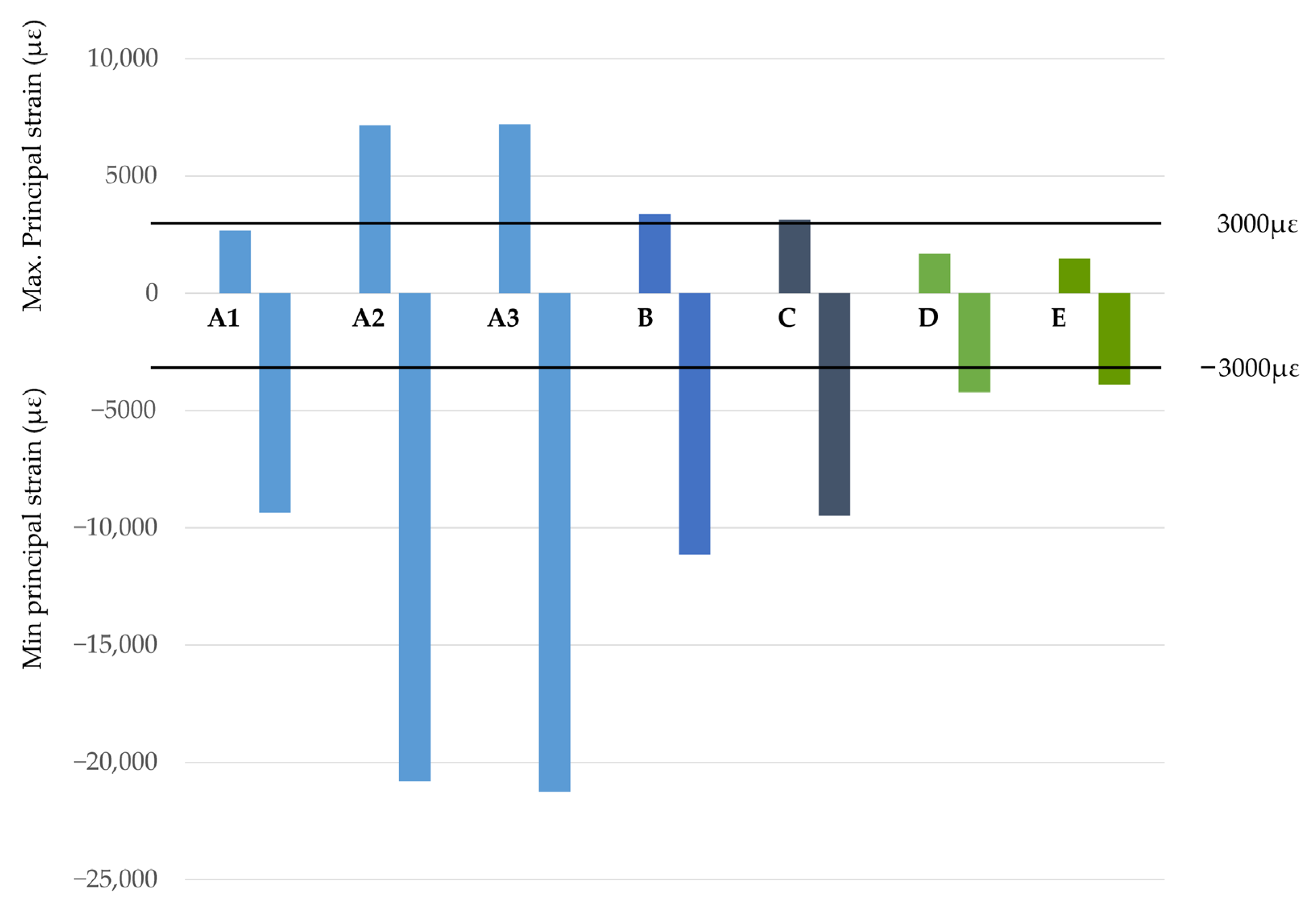
| Scenario | Implant Distribution | Max. Principal Strain (µε) | Min. Principal Strain (µε) | Von Mises Stress (MPa) | Cantilever (mm) |
|---|---|---|---|---|---|
| A-1 | 4 Axial implants | 2672 | −9362 | 149 | 11.5 |
| A-2 | 4 Implants, 2 tilted at 30° | 7151 | −20,810 | 321 | 11.5 |
| A-3 | 4 Implants, 2 tilted at 45° | 7200 | −21,250 | 435 | 11.5 |
| B | 5 Axial implants | 3359 | −11,150 | 199 | 11.5 |
| C | 6 Axial implants | 3144 | −9477 | 187 | 11.5 |
| D | 4 Implants: 2 distally placed from the foramina | 1669 | −4224 | 72.8 | 0 |
| E | 6 Implants: 2 distally placed from the foramina | 1468 | −3897 | 70.1 | 0 |
Disclaimer/Publisher’s Note: The statements, opinions and data contained in all publications are solely those of the individual author(s) and contributor(s) and not of MDPI and/or the editor(s). MDPI and/or the editor(s) disclaim responsibility for any injury to people or property resulting from any ideas, methods, instructions or products referred to in the content. |
© 2022 by the authors. Licensee MDPI, Basel, Switzerland. This article is an open access article distributed under the terms and conditions of the Creative Commons Attribution (CC BY) license (https://creativecommons.org/licenses/by/4.0/).
Share and Cite
Anitua, E.; Larrazabal Saez de Ibarra, N.; Saracho Rotaeche, L. Implant-Supported Prostheses in the Edentulous Mandible: Biomechanical Analysis of Different Implant Configurations via Finite Element Analysis. Dent. J. 2023, 11, 4. https://doi.org/10.3390/dj11010004
Anitua E, Larrazabal Saez de Ibarra N, Saracho Rotaeche L. Implant-Supported Prostheses in the Edentulous Mandible: Biomechanical Analysis of Different Implant Configurations via Finite Element Analysis. Dentistry Journal. 2023; 11(1):4. https://doi.org/10.3390/dj11010004
Chicago/Turabian StyleAnitua, Eduardo, Naiara Larrazabal Saez de Ibarra, and Luis Saracho Rotaeche. 2023. "Implant-Supported Prostheses in the Edentulous Mandible: Biomechanical Analysis of Different Implant Configurations via Finite Element Analysis" Dentistry Journal 11, no. 1: 4. https://doi.org/10.3390/dj11010004
APA StyleAnitua, E., Larrazabal Saez de Ibarra, N., & Saracho Rotaeche, L. (2023). Implant-Supported Prostheses in the Edentulous Mandible: Biomechanical Analysis of Different Implant Configurations via Finite Element Analysis. Dentistry Journal, 11(1), 4. https://doi.org/10.3390/dj11010004