2.2. Sample Postmortem Analysis
Before presenting the post treatment sample characteristics, it is worth noting that the diverse methods used to impinge in the sample (each described in the experimental methods section) impart very different levels of energy at very different time scales:
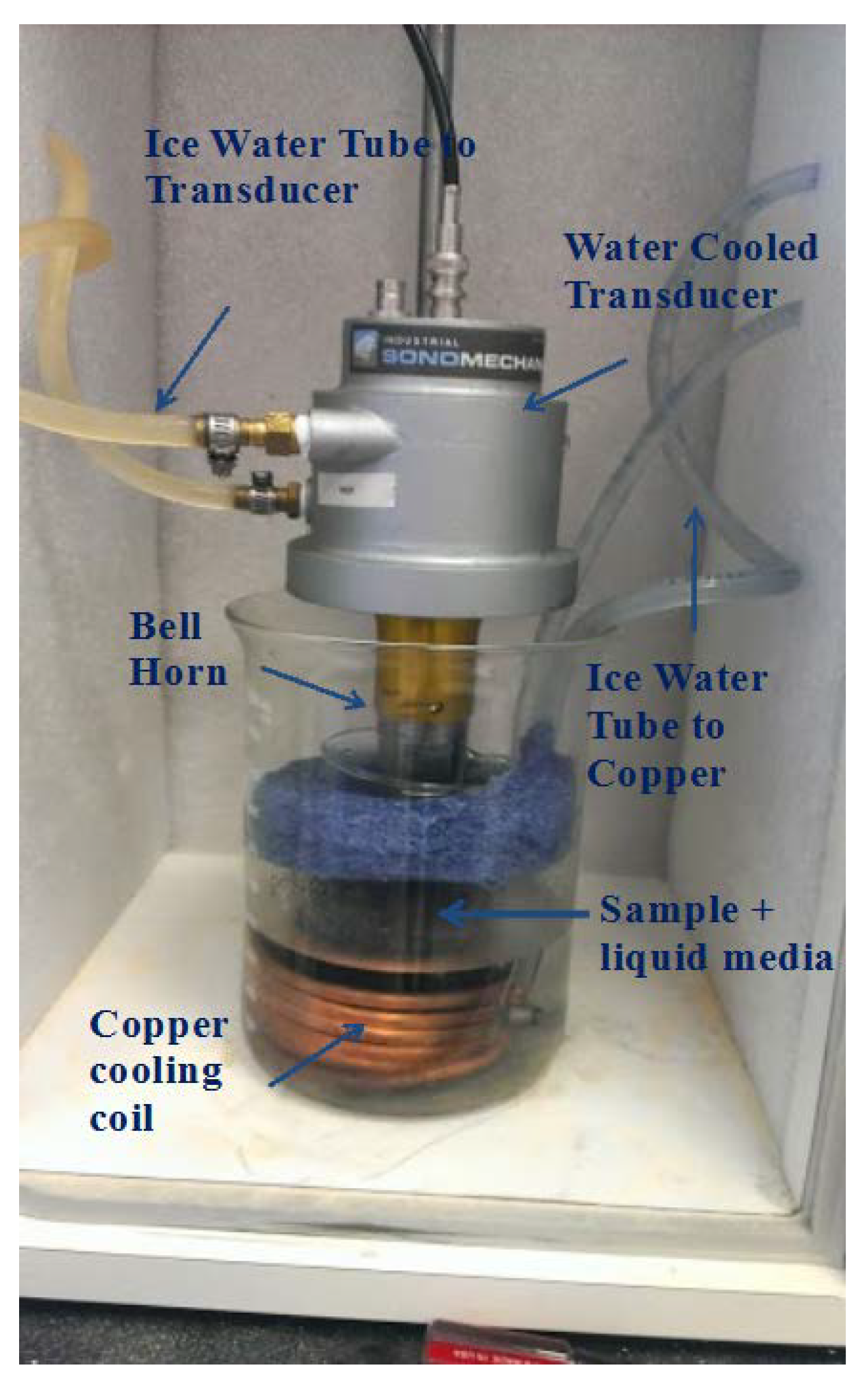
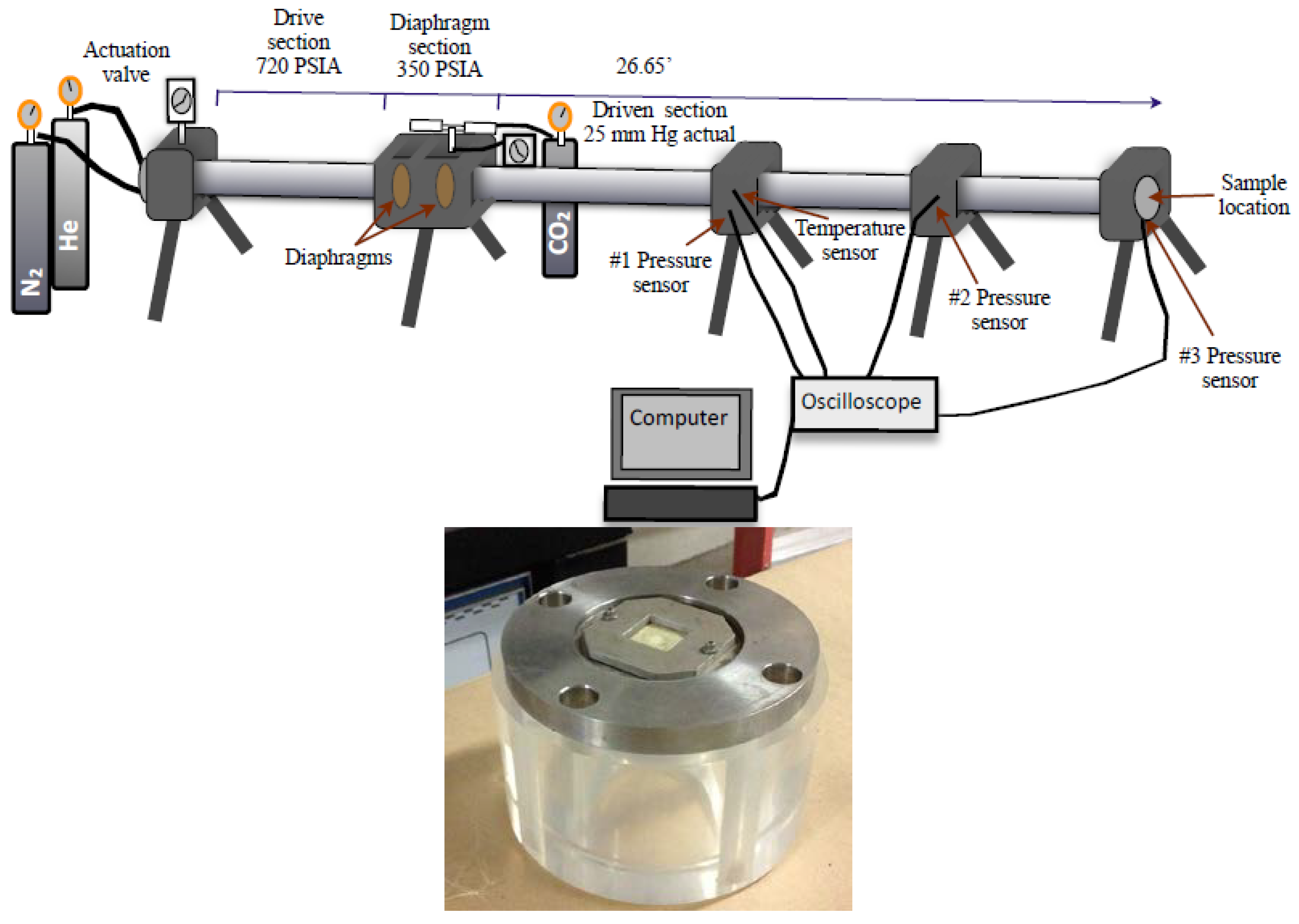
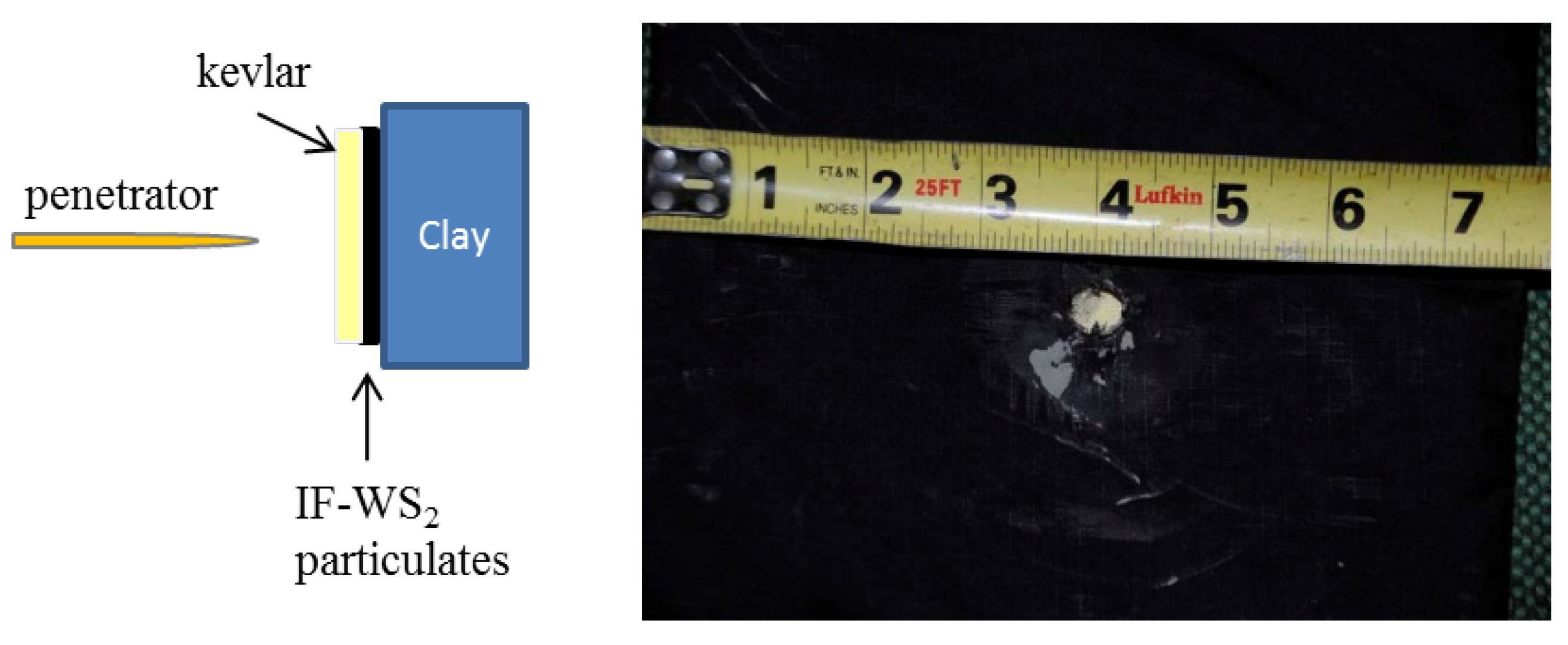
It has been estimated that the use of military rounds of the size used at the velocities recorded provided approximately 2070 Joules in a non-isotropic single event that lasted only fractions of a second. The compressed-gas driven shock tube experiment produced a wave that first impacted in the Kevlar layer located in front of the sample (which was used solely to contain the powder IF-WS2) impacting next the sample in a non-isotropic manner. This single incident also lasted fractions of a second. A pressure sensor located after the Kevlar layer recorded an average pressure of 1742 KPa when using He as the gas, as such, the estimated pressure of the wave that actually reached the sample. In contrast, during the ultrasonic treatment, the particles were completely immersed in a liquid, thus, being subject to isotropic shocks for much longer periods of time (between 3,600 and 10,800 s). The estimated energy conveyed when using a 1200 W ultrasound horn during such periods of time was from 4032 to 12,096 kilojoules respectively. In all cases, only IF-WS2 particulates were tested, no composites are included in this study.
Some research groups have studied the variations in the
d002 interlayer spacing in the samples before and after pressure loads using XRD powder data or TEM observations to relate such values to unit cell expansions or contractions [
17,
18]. Given the dispersion in lattice values noted by TEM studies mentioned above in the untreated samples, the extraction of useful postmortem TEM data could result very complicated. The change in lattice constant for IF-WS
2 seen before treatment arises from the differences in curvature between different locations of the polyhedral cage-like spherical or semispherical IF-WS
2 nanoparticles. To determine if XRD patterns could provide more reliable data, given that they include information from all the crystal locations and orientations, we performed such analysis for the samples treated by the three loading methods.
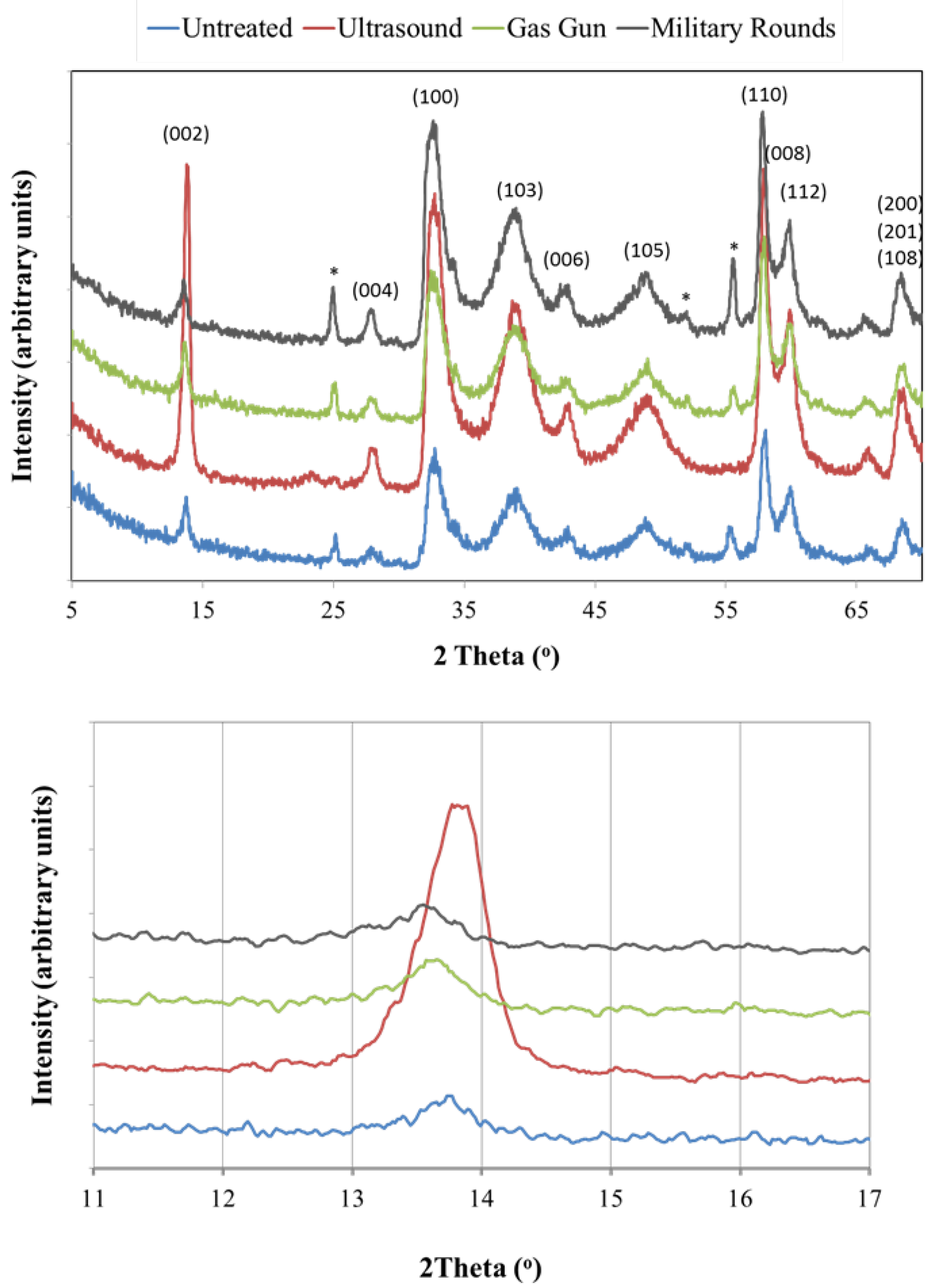
The XRD patterns of samples subjected to the diverse treatments are shown in
Figure 2. The graph in the upper section of the image shows the peaks encountered between 5° and 70° (2θ), while the bottom image presents only the (002) peak. Specimens treated by ultrasound waves in wet conditions (dispersed in a solvent) and then dried for the analysis, present a (002) reflection that has shifted to higher angles. This alteration in the X-ray pattern indicates a reduction in the cell spacing when compared to the untreated sample. A similar observation was made in references above [
17,
18]. We believed that such shift could be related not only to a compressed IF cell but to a phase transition from the IF cage structure to a more dense 2D plate-like WS
2 arrangement with slightly smaller 00l distance. The width of the (002) XRD peak for ultrasound treated powders in
Figure 2 (red line) might suggest the presence of both, IF-WS
2 and two-dimensional WS
2 in the same powder sample.
The peaks identified with the * symbol do not belong to WS2 but to WO3. The existence of small amounts of WO3 could not be verified by EDS analysis of large portions of the sample by SEM but was clearly identified by TEM of selected locations (uploaded as Figure S1).
By comparison, the samples collected after shock tube tests and military rounds insult show either no change or a slight shift to lower angles. Such result could be interpreted as no modification of the structure or a small expansion in the lattice parameter. We believe, however, that disparity in those results, when compared to the ultrasonic treated sample, might be more related to the experimental constrains faced when collecting the powders than a clear representation of the specimen features. The collection of the section of the sample that was directly exposed to the shockwave or to the impact of the penetrator was difficult; the particles had the tendency to get expelled from the impact site and only some of them remained in the center of the tested specimen or close to the hole left by the round and got recovered. That is, the XRD signal represents the average of all the particles gathered in the postmortem, some of which were not as affected by the event as the ones at the center of the impact location. In the case of ultrasonic treatment, the full sample was contained at all times and all particles were equally affected by the treatment, therefore rendering a powder that presented more uniform features and more reliable data, thus confirming a shift in the d002.
Figure 2.
X-ray diffraction analysis of particulates recovered after treatments. Top: reflections observed between 5° and 70°; Bottom: (002) peak for all samples. Only the sample gathered after ultrasonic treatment showed a shift to higher angles. The symbol * identifies a WO3 peak.
Figure 2.
X-ray diffraction analysis of particulates recovered after treatments. Top: reflections observed between 5° and 70°; Bottom: (002) peak for all samples. Only the sample gathered after ultrasonic treatment showed a shift to higher angles. The symbol * identifies a WO3 peak.
The precise effects of applying diverse loading conditions in the specimens’ microstructures were much more evident once the samples were studied by electron microscopy. We were able to conduct the analysis with smaller amounts of sample and use only particulates from affected locations.
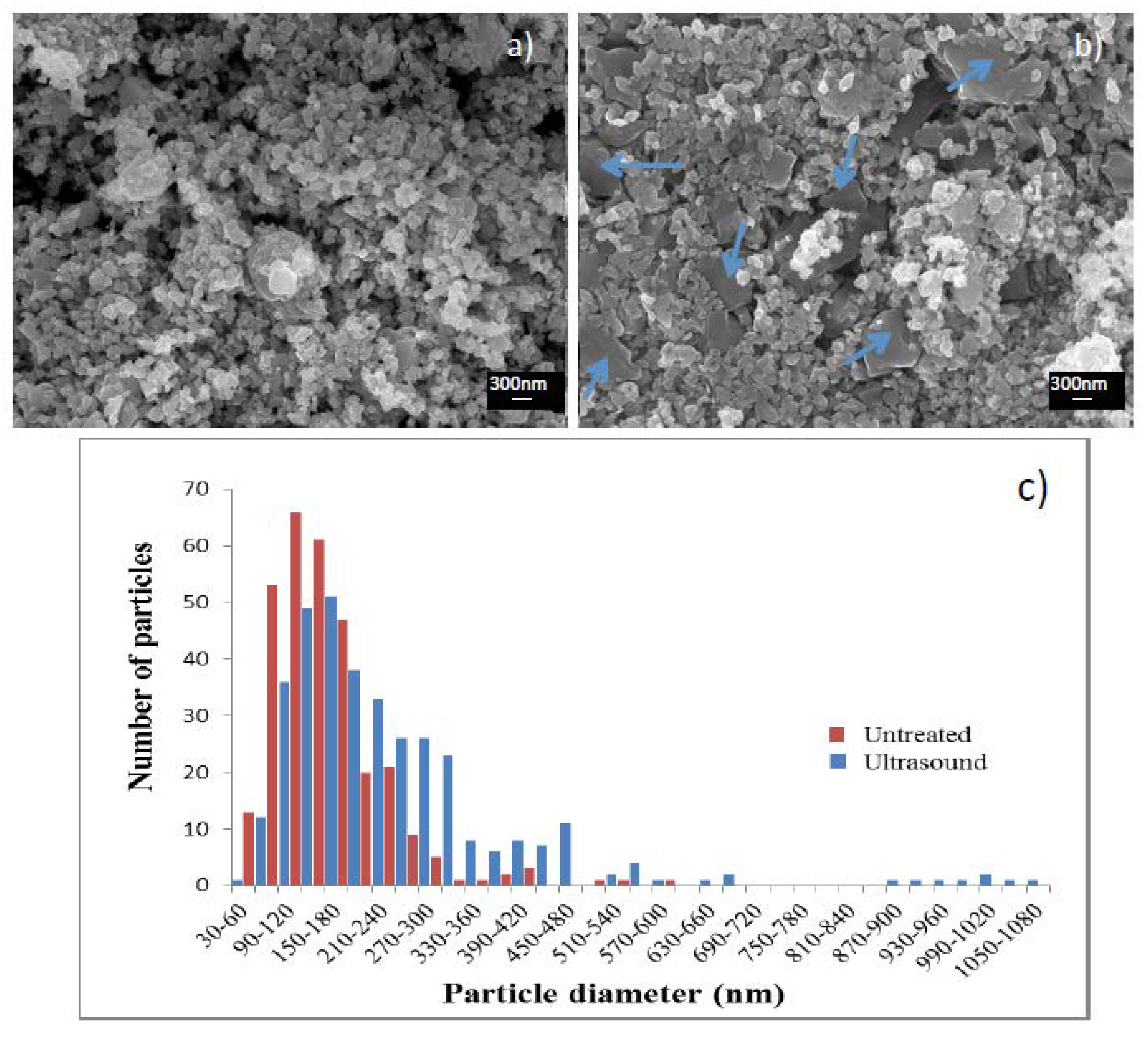
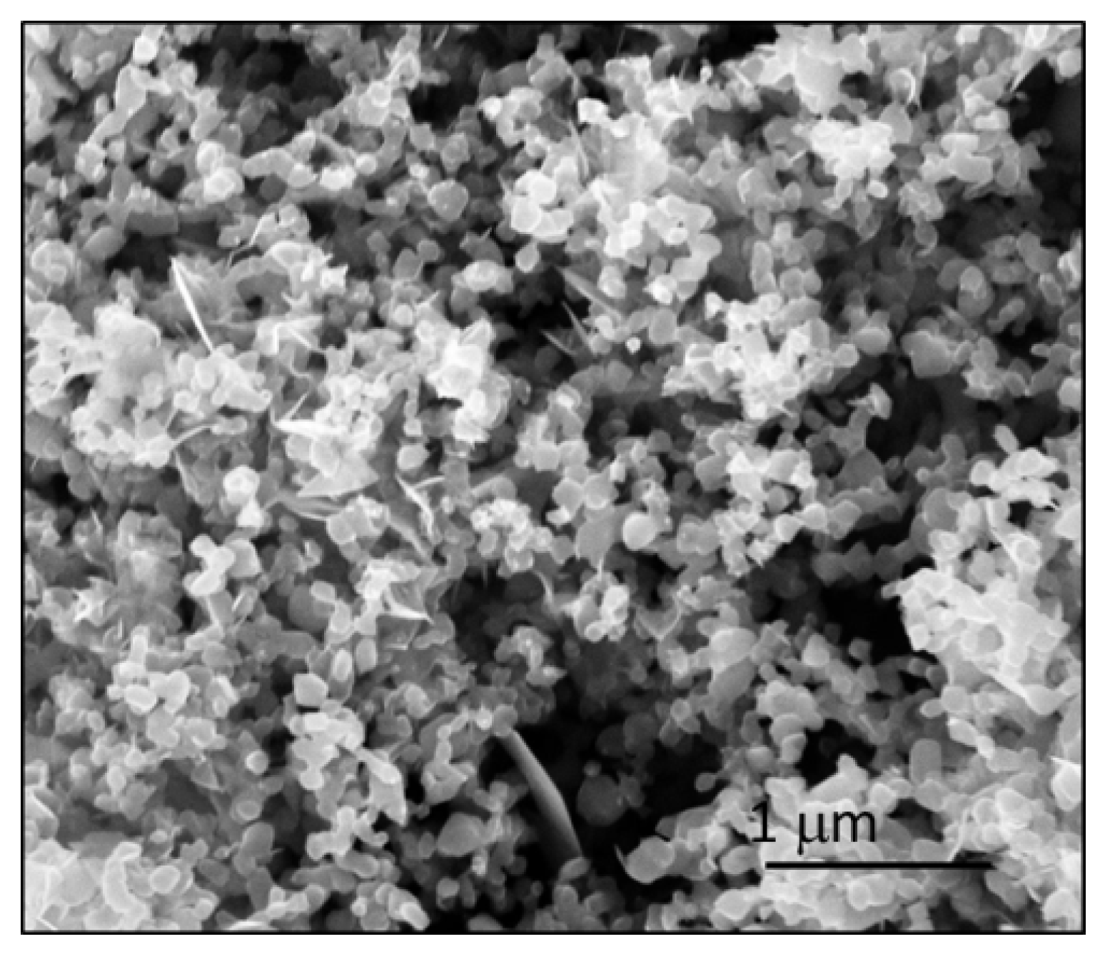
Figure 3 presents a SEM image of the IF-WS
2 particles before (a) and after (b) ultrasonic treatment. The existence of extended layered structures (identified with arrows) along with the original IF polyhedral, semispherical shapes is the most noticeable change. According to particle size distribution measurements (
Figure 3c) the average diameter of the particles in the sample after treatment has shifted to larger sizes, 252 nm (blue histogram), and clearly shows a bimodal distribution. Particles between 800 nm and 1 micron, not seen in the untreated sample, are present in the ultrasonic treated specimen. The larger plate-like particulates correspond to the 2D polymorph and no longer present the hollow cage structure of IF-WS
2. The appearance of the 2D phase supports the XRD data collected regarding both, the XRD peak shift and its width, and agrees with the initial reports suggesting a lattice compression [
17,
18]. Notably, the particles did not only collapsed and lose their hollow cores; they also transformed into 2D structures and then suffered an agglomeration mechanism that turned them into much larger, irregular shape units.
Figure 3.
SEM micrographs of (a) untreated particles, (b) samples treated with ultrasonic horn during 3 h at 20% amplitude (17 µpp). Note the appearance of layered particles of much larger dimensions than original spheroids; (c) Particle diameter comparison between the two samples.
Figure 3.
SEM micrographs of (a) untreated particles, (b) samples treated with ultrasonic horn during 3 h at 20% amplitude (17 µpp). Note the appearance of layered particles of much larger dimensions than original spheroids; (c) Particle diameter comparison between the two samples.
Given those observations, we have denominated this transformation or fracture mode as “agglomeration”, since the collapsed particles seem to have larger dimensions after the experiment, implying the agglomeration of many of the original IF spheroids. However, agglomeration is a general term that only refers to the enlargement of the particles and does not completely account for all the complex steps that the particles suffer during this failure mode. Some of the stages we believe are necessary for the 2D polymorphs to acquire the sizes observed imply: (i) an initial crack formed in the surface of the IF particles; (ii) crack propagation towards the core, leading to a complete fracture of the walls; (iii) a structure collapse and disappearance of the hollow cores; (iv) sheets re-arrangement; and (v) new bonds being formed. Moreover, the large sheet-like particles in
Figure 3c show little evidence of grain boundaries, which suggests the involvement of a sintering or crystal growth mechanism, rather than simple agglomeration. Some of the flattened sections (
Figure 3c) reached even micrometer lengths, far from the 143 nm average diameter in the untreated IF-WS
2.
The temperature during the sonication experiments was controlled by an ice bath to prevent solvent evaporation. Nevertheless, given that the particles were exposed to the ultrasonic waves during extended periods of time (up to 10,800 s in some cases) the process seems to have provided enough energy to allow all the steps mentioned above to happen (i–v), followed by crystal growth. The fact that the (002) peak for ultrasound sample, in
Figure 2, is much more intense than the one from the untreated specimen supports the idea that more particles with such orientation exist, as is typical of layered structures, fact now verified also by the SEM data.
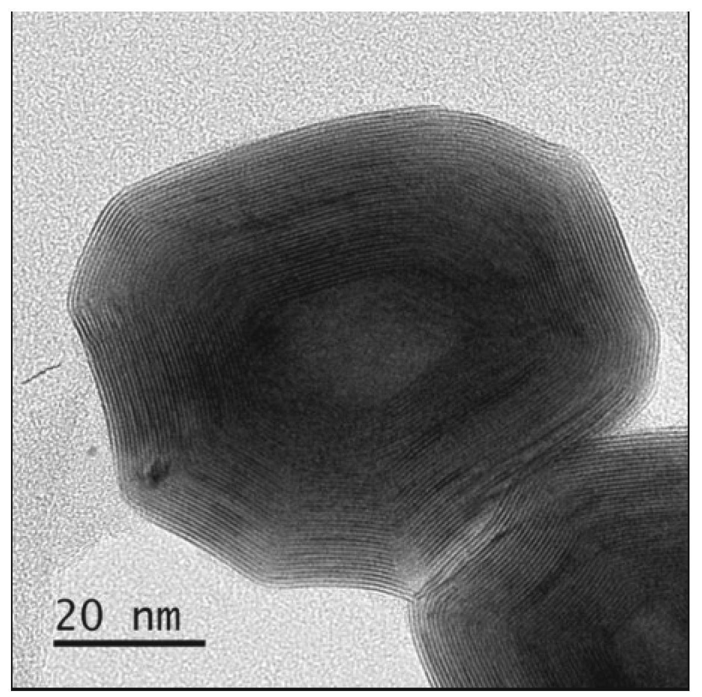
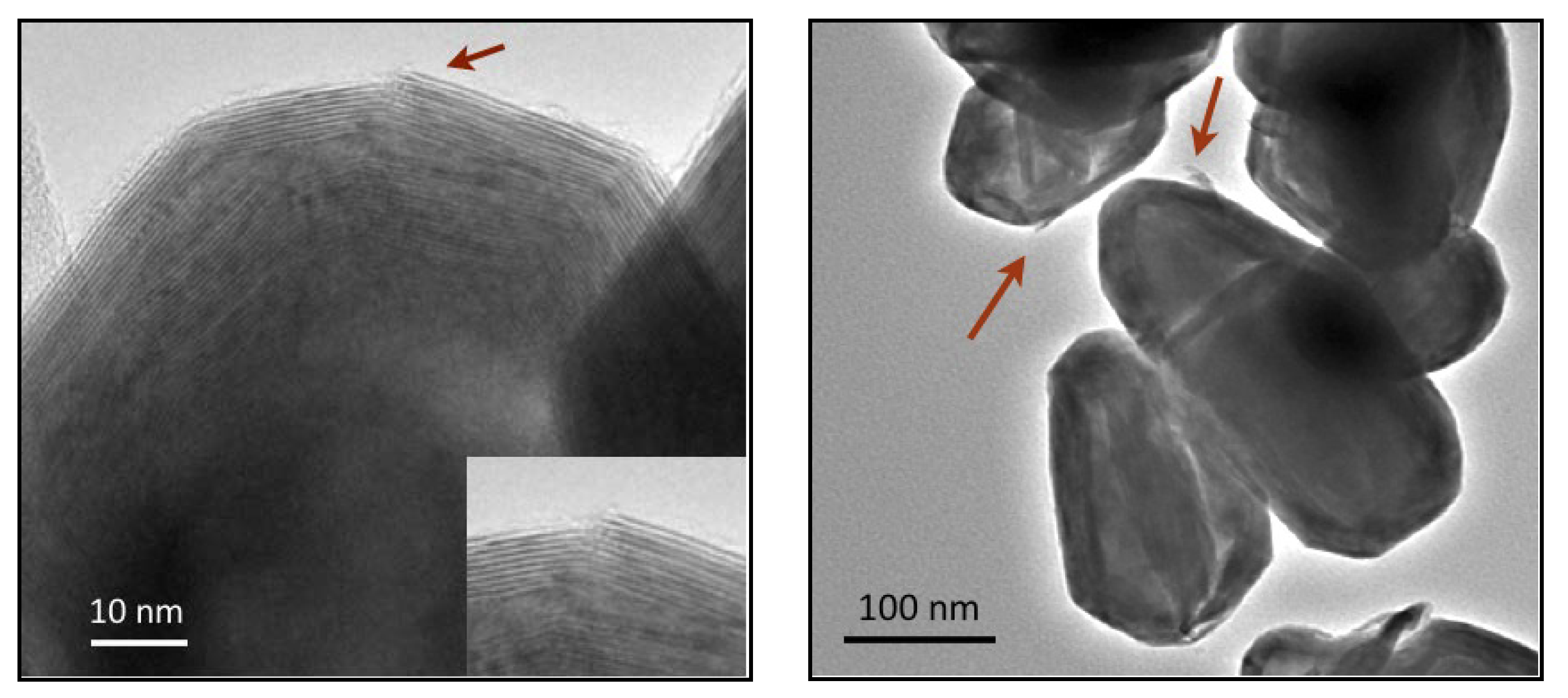
The study of the ultrasonic sample postmortem by transmission electron microscopy corroborates the existence of both the 2D and 3D (IF) polymorphs. The TEM study of the IF particles that did not collapse presented evidence of crack initiation in the vertices of the polyhedrons.
Figure 4 (left) shows one of those cracks, which has not yet propagated through the whole structure. In a similar fashion that surface defects can promote the fracture of macroscopic objects at smaller levels of stress than the ones predicted by theoretical calculations, in IF-WS
2 nanostructures the imperfections in the particles’ surfaces act as stress concentrators. No WO
3 was identified in the specific particle structure where such observations were made, ruling out its effect in the particle fracture mechanisms.
Figure 4.
Left: TEM micrograph of a particle treated with ultrasonic horn that presents a surface crack. The inset is a magnified version of the area pointed by the arrow; Right: TEM studies corroborated the damage of both, internal and external layers of the IF structures.
Figure 4.
Left: TEM micrograph of a particle treated with ultrasonic horn that presents a surface crack. The inset is a magnified version of the area pointed by the arrow; Right: TEM studies corroborated the damage of both, internal and external layers of the IF structures.
As pointed out in multiple references [
19,
20,
21,
22], materials do not fracture while in compression, they fracture in tension. The failure modes observed in samples post ultrasonic treatment present a similar signature as the ones expected from fatigue experiments; they resemble the fracture of materials that have been subjected to a cyclic load which involves the contraction and expansion of the structure. We found evidence of breakage in the surface (crack in
Figure 4 left) presumably created during one of the expansion cycles while in tension. However, there is also evidence of some of the sheets breaking inside the particles’ core (
Figure 4 right), indicating a similar mechanism occurring but in the opposite direction, pointing to a cyclic load.
The complete breakage of the outer layers in the crack area (in
Figure 4 left) seem to happen without extensive plastic deformation, resembling the typical brittle failure. Such feature is observed in many particles and diverse sections of the sample. However, we also identified particles that present a slightly larger separation between the first and second layers of the lattice than the one found for the inner layers. Such a fact can be interpreted as evidence of a very small amount of plastic deformation occurring in the direction perpendicular to the lattice fringes.
Apart from the multiple particles suffering the agglomeration type failure (fracture-agglomeration-phase transformation steps described before), a second mechanism was identified by the observation of the samples by TEM: incipient “delamination”. Indeed, small sections (
ca. 10–15 nm) of a few of the IF particles seem to partially separate from the main body of the structure.
Figure 4 (right) exemplifies that case, the arrows pointing to sites of partial delamination. A similar exfoliating mechanism has been observed by other groups [
17,
23]. We did not find evidence of larger sections or complete layers totally separating from the IF spheroids in the ultrasonic treated specimens. The amount of particles presenting partial delamination, when compared to the amount that presented agglomeration, was minimal.
The main difference found between the two failure modes is that agglomeration mechanism destroys the hollow cage structures, generating 2D extended structures, and delamination does not. The main parallelism between them is that both, incipient delamination in the outer layers of the IF structures, and crack formation with propagation towards the particle core are observed in the vicinity of vertices, edges or surface defects.
The fact that the vertices in untreated particulates presented a larger average interlayer distance (0.63 nm) than the faceted sides or walls (0.62 nm) is suspected to have an influence over which failure more (agglomeration vs. delamination) is predominant. However, the difference between such values is so small that more data and a higher resolution instrument might be required to be able to make a definitive correlation.
There is no evidence that suggest that one failure mode represents a first step towards the other. The transformation between the IF particles and the 2D structures in the agglomeration mode seem to start with a crack that advances towards the particle core, feature observed in samples treated in different conditions. The few cases of delamination seen do not exhibit such crack directionality but a separation of only the outer layers. The failure modes do not seem to be associated to particle sizes either. Perfect spherical particles might present a correlation between such since the size will determine the radius of curvature, which is a factor that affects the crack propagation in macroscopic objects.
One of the main limitations we encountered during this study was the lack of a method to quantify the level of damage that the samples suffered. From the SEM images we could estimate the percentage of the sample surface that transformed into larger particles due to the agglomeration mechanism (as in
Figure 3). However, multiple images need to be taken to assure that the features observed actually represent the bulk of the sample and the existence of the flat particles underneath the surface layer of the sample could be overlooked. Since the most common failure mechanism observed by large was agglomeration, and only very small sections of the sample delaminated, we contemplated the use of surface area measurements to evaluate the level of damage. Indeed, most particles suffer an enlargement that will produce a surface area reduction (due to the agglomeration mechanism) and only a few of them will have more area exposed (due to delamination).
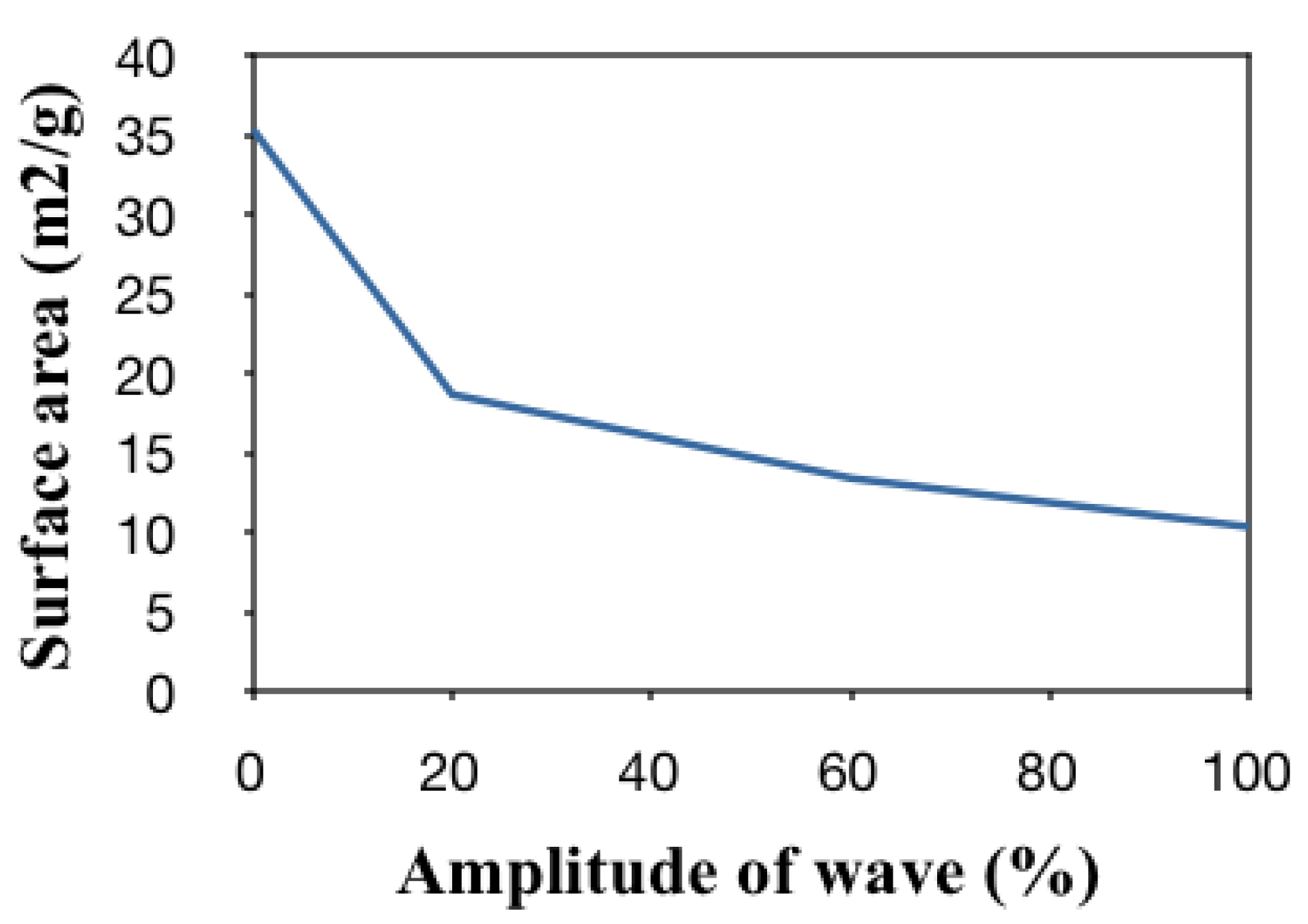
The surface area data from samples treated with the ultrasonic horn at diverse amplitudes was calculated using the BET methodology and is presented in
Figure 5. Samples treated at higher amplitudes or for longer periods of time (not shown) suffer an evident surface area reduction. Both amplitude and time imply more energy being imparted to the particles. The former because the energy transported by a wave is directly proportional to the square of the amplitude of the wave: A high-energy wave is characterized by a high amplitude; a low-energy wave is characterized by a low amplitude. The latter, because energy is calculated directly from the product of the Watts provided by the source and the time of the treatment. The trend towards smaller surface areas in
Figure 5 could be correlated to particle agglomeration and the presence of extended 2D layered structures, as the ones seen in the example presented in
Figure 3.
Figure 5.
Surface area analysis (m2/g) vs. amplitude found for samples subjected to ultrasonic treatments.
Figure 5.
Surface area analysis (m2/g) vs. amplitude found for samples subjected to ultrasonic treatments.
The BET surface area measurement does not provide a definitive way to evaluate damage when both agglomeration and delamination occur in large extents. However, it provided a way to compare the extent of damage in bulk samples when agglomeration was the dominant mechanism (as in the ultrasound treated samples) without the need for lengthy SEM/TEM analysis.
As previously stated, the study of samples by electron microscopy provided a more definitive proof of the changes that the IF-WS
2 structure suffered under load than the shifts observed in the XRD analysis alone. Such was particularly true for the samples subjected to shockwave tests and impacted with military rounds, since smaller amounts of powder could be analyzed and only particulates from insulted regions were collected. See
Figure 6.
Figure 6.
Cracks in the vertices of the particles are the only evidence of damage in samples subjected to shock tube tests. No crack propagation or structure collapse was observed. No evidence of delamination was found either.
Figure 6.
Cracks in the vertices of the particles are the only evidence of damage in samples subjected to shock tube tests. No crack propagation or structure collapse was observed. No evidence of delamination was found either.
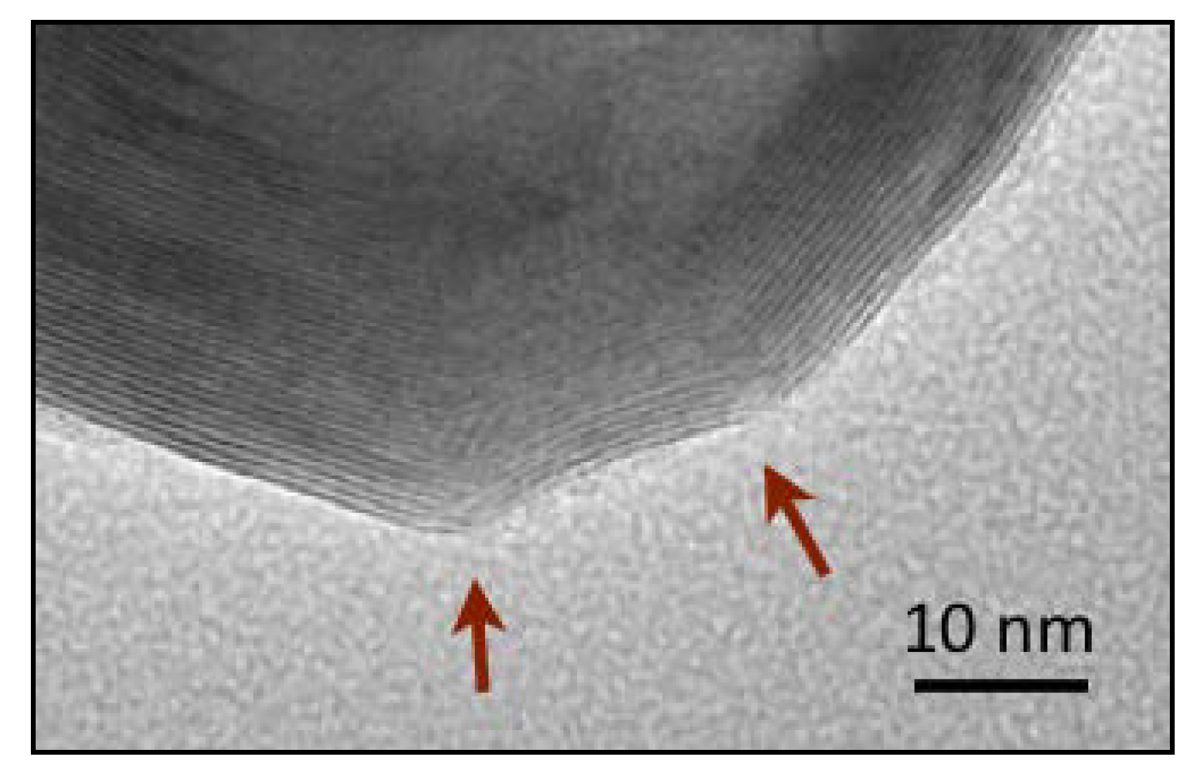
The evaluation of the samples treated by shockwaves revealed that the damage sustained was less than the one observed for ultrasonic methods, as expected from the low pressures registered by the sensors. The SEM observation of the sample from shock tube revealed that only very small sections of the sample showed agglomeration. TEM images showed crack initiation and
Figure 6 exemplifies this feature. The arrows on the image point to two different sites where the crystal structure fractured. The pressures used by shockwaves produced by N
2 and by He were not enough to cause the sample to suffer a complete collapse. We did not find evidence of delamination in any of the multiple particles analyzed. Thus, we found no evidence that the agglomeration failure mode is preceded by delamination.
Samples impinged with military rounds suffered a larger level of damage than that observed for shock tube tests. Unfortunately, as stated before, it was difficult to collect large amounts of sample in the circumference left by the penetrator, reason for the XRD and BET data not to be as reliable as the one seen for ultrasonic treatments. Nevertheless, the SEM analysis of the sample provided proof of the same mechanisms described earlier in this article. We found layered structures similar to the ones in
Figure 3b; however, in this case the agglomerates reached not only micrometer dimensions in length and width, but also in height. There are regions in the postmortem sample that the IF particles can still be encountered but the agglomerates are much more abundant.
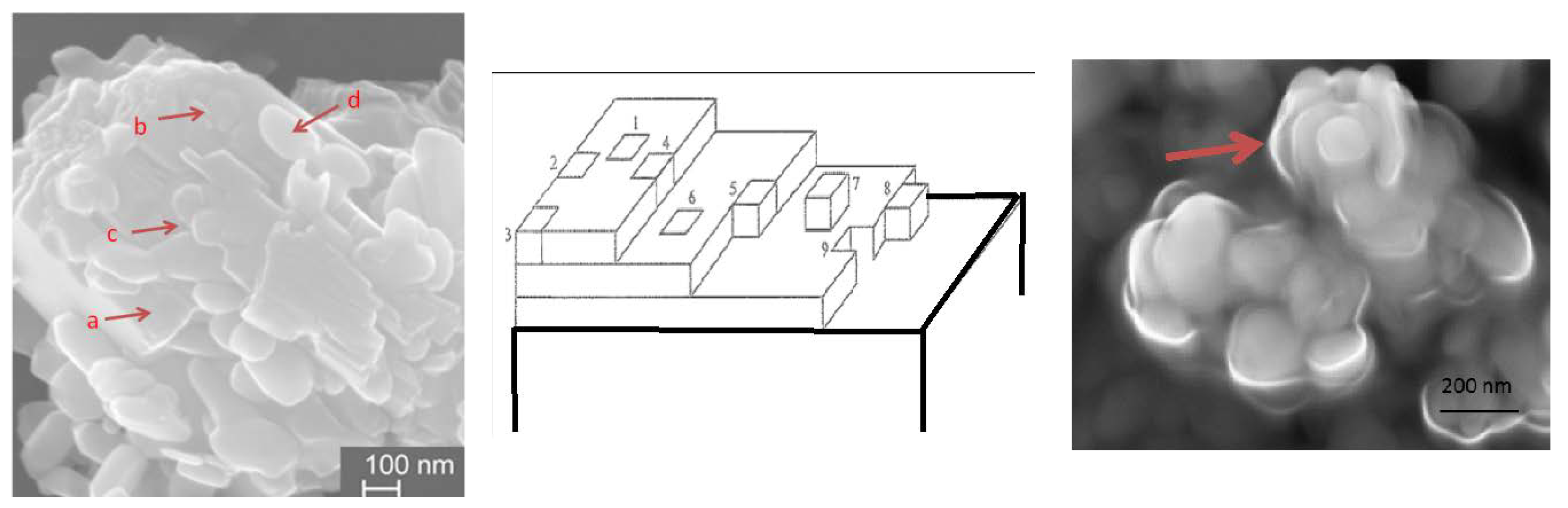
Figure 7 shows both, the more frequently observed agglomeration (left) and an image of the less common delamination (right). Regarding the agglomeration case, once the IF particles fracture at the polyhedron vertices or edges, they collapse, their sheets re-arrange to diminish any spaces in between layers and are added to the larger crystals in a fashion similar to the one observed during crystal growth (
Figure 7 center). In
Figure 7 left, grain boundaries mark the regions where IF particles have joined the main particle. The letters in the figure represent: (a) matter has completely been incorporated onto the agglomerate and is now part of the surface to which new particles will connect; (b) the grain boundaries of the initial IF particle are still visible within the main body of the agglomerate; (c) a new layer is being formed, some sections of the same present layered structure with sharp edges and others partially conserve the spherical shape; and (d) an IF-WS
2 semispherical particle still lays in the surface.
Figure 7.
Sample recovered from impact with military rounds. Note the similarities between regions where IF have been added to an existent layered structure, such as a, b, c, and d (left) with sites proposed by crystal growth theories for addition matter in a surface (center). Particle showing layers that delaminated (right).
The angles in the vertices in the polyhedral particles seem to play a similar role than the radius of curvature of the surface or internal cracks have in traditional fracture mechanics analysis. Furthermore, the larger crystal to which other IF are being added present imperfections such as kinks, ledges, steps,
etc. Each of those sites represent regions in the sample where dangling bonds exist; those locations are more prone to accept the addition of new matter to reduce the overall surface energy as is usually described by crystal growth theories [
24,
25]. According to the latter, the thermodynamics of crystal surface formation and transformation is based on the idea that the energy that each atom’s position on a crystal surface is determined by the number of neighboring atoms and the amount of unsatisfied bonds. The numbers in
Figure 7 (center) represent: surface atoms, surface vacancies, adatoms, kinks, and steps.
Figure 7 (right): this image represents the only instance that we found of what it seems as a complete layer delamination; the outer sheets of the material seem to come apart to reveal an inner particle still intact.
The effect of temperature in the material agglomeration during the military round impact certainly plays a significant role to transform the IF into extended sheet-like WS2 structures. However, given the complexity of the test, no temperature values were recorded and the heat effect will only be subject of further study and discussion in future reports.
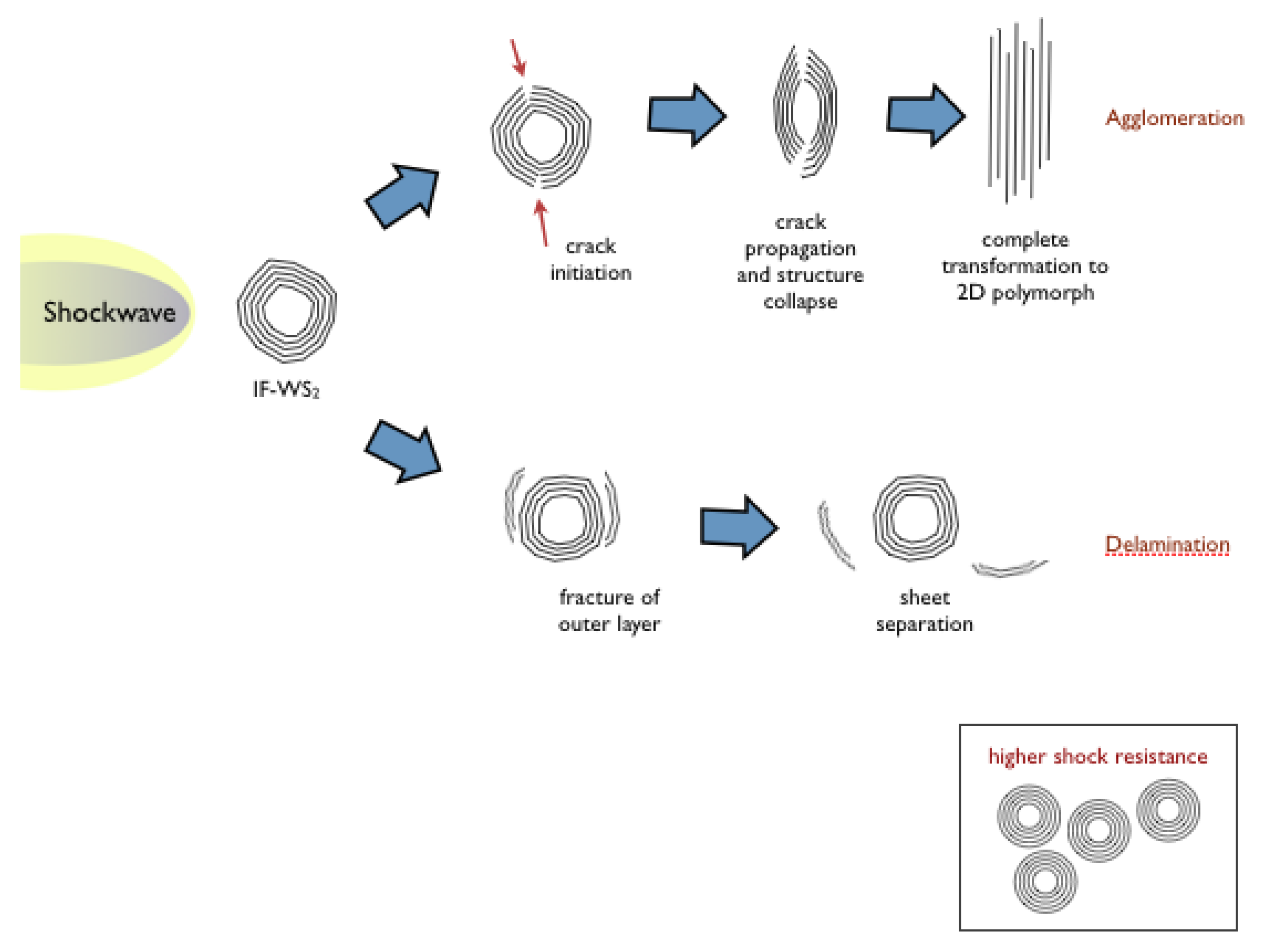
Figure 8 summarizes our findings. In the agglomeration mechanism: IF particles are more susceptible to breakage in areas where defects or discontinuities, such as edges and vertices, are located. Those act as stress raisers and are the primary sites where crack initiates, in the outer layers of the cage structures. Once the crack propagates it will reach the hollow cores, which will promote the particles collapse and the transition between the 3D and the 2D WS
2 polymorphs. The layered structures will agglomerate to reach micron scale dimensions. The collapse and agglomeration of the IF structures was the main effect identified as a consequence of the application of ultrasonic treatment in diverse conditions and the use of military rounds despite the diverse time scale of each of those methods. Shock waves in the conditions employed only produced surface cracks without the full structure collapse. Agglomeration signature is identified as the predominant mechanism in the experimental conditions used.
Figure 8.
Representation of the two failure modes identified in the IF-WS2 structures.
Figure 8.
Representation of the two failure modes identified in the IF-WS2 structures.
We also identified evidence that suggests that the particles can suffer delamination. The areas in the IF particles surface where this failure mode was identified also correspond to locations where defects or discontinuities are observed. During this failure mode the Van der Waals attraction keeping the layers in the together is broken as a consequence of the shock and small portions of the outer layer come apart, leaving behind sections with a smaller diameter particle but still IF characteristics. The separation between surface layers do not seem to propagate into internal layers. Remarkably, during our experiments we observed incipient delamination in only very few particles treated by sonication. No correlation was found between the extent of this failure mode and times of treatment. We observed only one instance of an almost complete layer separation (
Figure 7c).
In sum, all the electron microscopy observations conducted in the postmortem products point to the existence of surface flaws as starting point where agglomeration or delamination take place, independent of the amount energy imparted by the insult, the time of the event or the isotropic or non-isotropic nature of the experiment.
The structure fails by two modes: either as a consequence of the creation of a surface crack and its propagation into the hollow core, followed by the structure collapse and resulting in the transformation into a 2D sheet-like polymorph and the agglomeration of particles into larger bodies, or by delamination of small sections of the sample, which does not completely destroy the IF structure but removes superficial sections, leaving the hollow cores and inner walls intact.
What conditions favor agglomeration over delamination is still subject of study. No link has been found here between the two fracture mechanisms and levels of stress. Crack formation, usually followed by propagation and structure collapse has been identified without evidence of delamination at diverse levels of stress and over a wide range of times of treatment. The interlayer separation and the radius of curvature (given by particle size and existence of faceted structures) are suspected to play a role on which mode dominates however, such has not been clearly demonstrated/quantified.
Studies of brittle fracture demonstrate that the experimental fracture strengths of most materials are lower than the theoretical ones (based on calculations related to atomic bond energies) due to the existence of microscopic flaws that act as stress raisers, amplifying the stress at a given point. The postmortem TEM analyses indicate that the IF-WS
2 particles deform and break where structural discontinuities appear: defects and edges in the polyhedral shapes, along the degree of curvature of the particulates, seem to play a critical role on the material resistance to breakage, following a pattern similar to the ones observed in more general fracture mechanics principles. These findings provide evidence that without the stress concentrators in the particle surface, as would be the case if more spherical particles were used, the material should be able to support higher pressure loadings, supporting previous reports [
17]. The bottom of
Figure 8 shows a schematic representation of how such particles will look like.
No evidence of crack formation or delamination was seen in the more uniform sections of the particle surfaces. These results suggest that IF-WS
2 is prone to show a phase transformation into a 2D polymorph and only near spherical particles might show remarkable shock absorption characteristics. Despite finding that the structures have similar failure modes than their carbon counterparts, which can diminish their shock resistance, our findings also point to a solution to the failure: use of defect free (more spherical, not faceted) particulates, supporting previous statements made by Tenne
et al. [
17].
It is worth noting that the creation of defect free IF-WS
2 particles might prove challenging; the use of completely spherical WO
3 produced by microwave plasma methods in our labs and reacted with H
2S, produced highly faceted IF-WS
2, see
Figure 9. Different treatment conditions should be developed in order to achieve completely spherical nanoparticles.
Figure 9.
IF-WS2 generated at 900 °C from the WO3 produced using a microwave atmospheric plasma system. Despite the highly spherical nature of the precursor, the IF-WS2 particulates present facets and polyhedral shapes. A few atoms thick 2D WS2 were also observed.
Figure 9.
IF-WS2 generated at 900 °C from the WO3 produced using a microwave atmospheric plasma system. Despite the highly spherical nature of the precursor, the IF-WS2 particulates present facets and polyhedral shapes. A few atoms thick 2D WS2 were also observed.
With failure modes now clearly characterized future research could (a) correlate the cracks observed, the angles at the vertices and the levels of stress used, to generate mathematical expressions that could predict mechanical properties such as fracture toughness for the particular size of IF-WS2 and (b) design nanoparticles against fracture.

