Review

Carbon Nanomaterials for Electrochemical Hydrogen Storage: Mechanisms and Advancements

by
Amir Reza Mashtizadeh
1,
Shahab Khameneh Asl
1,
Hossein Aghajani
2,
Seyed Morteza Masoudpanah
2 and
Marek Wojnicki
3,*
1
Department of Materials Engineering, University of Tabriz, Tabriz 51666-16471, Iran
2
School of Metallurgy & Materials Engineering, Iran University of Science & Technology, Narmak, Tehran 16846-13114, Iran
3
Faculty of Non-Ferrous Metals, AGH University of Krakow, Mickiewicza Ave. 30, 30-059 Krakow, Poland
*
Author to whom correspondence should be addressed.
Inorganics 2025, 13(4), 125; https://doi.org/10.3390/inorganics13040125
Submission received: 13 February 2025 / Revised: 23 March 2025 / Accepted: 2 April 2025 / Published: 17 April 2025

Abstract

:
This review article investigates the rising global energy demand, which is primarily driven by population growth and industrialization, raising significant environmental concerns due to the extensive reliance on fossil fuels. In response, hydrogen is being explored as a potential eco-friendly energy solution to meet the urgent need for sustainable energy. This review covers various hydrogen storage methods, including compressed gas, cryogenic liquids, solid materials, and electrochemical techniques. Among these, electrochemical technology is highly regarded as a leading experimental approach for hydrogen storage, and it is noted for its outstanding performance under normal conditions. The characteristics of a material’s surface play a crucial role in determining its electrochemical hydrogen storage capacity. Innovative materials, such as graphene oxide and 3D graphene oxide, are particularly significant in this regard, as they can significantly enhance hydrogen storage capacity; electrochemical hydrogen storage functions by incorporating atomic hydrogen into carbon materials following the reduction of water. This article underscores the significance of green energy and the need to ensure safety and precision at room temperature and ambient pressure using electrochemical hydrogen storage techniques and mechanisms. Furthermore, it offers a comprehensive review of developments in electrochemical hydrogen storage and its mechanisms, focusing on carbon, graphene oxide, and the contributions of 3D graphene foam.

1. Introduction

The global energy demand, driven by population growth and industrialization, has increased environmental concerns due to the widespread use of fossil fuels. Despite their current popularity, these fuels emit greenhouse gases. Moreover, their resources are limited. Intensive use of fossil fuels results in environmental damage and climate change. This situation underlines the urgency of exploring sustainable and eco-friendly energy alternatives. Some sustainable and clean energy systems can reduce carbon emissions, such as wind, solar cells, and hydrogen storage [1,2,3]. Hydrogen is a promising fuel because it is widely available, lightweight, and packed with energy. Since it produces no carbon emissions, it is an environmentally friendly alternative to fossil fuels [4,5,6]. Efficient hydrogen storage methods are essential to achieving a hydrogen-based economy. The main hydrogen storage methods include compressed gas, cryogenic liquid, solid-material-based methods, and electrochemical hydrogen storage [6,7,8,9,10]. Regarding tank construction costs, space requirements, and safety concerns, compressed gas storage requires high-pressure tanks, making it economically challenging. Specialized tanks with double-walled insulation are necessary for cryogenic storage, which involves cooling hydrogen to very low temperatures; this reduces the efficiency of cryogenic liquid storage [9,11]. According to the International Energy Agency’s Renewable Energy Report 2021 [11], the world’s top ten renewable-energy-producing countries are expected to account for about 80% of global installed capacity between 2021 and 2026, as shown in Figure 1. China alone is projected to contribute over 43%, followed by the United States and India at 12% and 7%, respectively. As global energy demand continues to rise in the coming decades, the pressure on energy supply and environmental sustainability will also increase [12,13].
Electrochemical hydrogen storage is another system with good prospects. The two main reasons for this are that electrochemicals have low energy density and serious safety issues. It seems that the emerging technique of electrochemical hydrogen storage is the ultimate approach for realizing the benefits of hydrogen [12]. Using hydrogen as an energy carrier is widely recognized as a highly effective approach to generating energy and a viable alternative to fossil fuels. Numerous studies have been conducted to find suitable materials for storing hydrogen. Different materials such as metal hydrides, zeolites, metal–organic frameworks, nanomaterials, and carbon nanocomposites are suitable for hydrogen storage due to their high specific surface. Solid materials with high specific surfaces have been developed to safely store hydrogen at room temperature. Solid-material-based hydrogen storage offers enhanced safety, a high volumetric capacity, and operation at lower temperatures and pressure levels.
The solid-state storage of hydrogen, particularly in its H2 molecular form, aims to tackle specific challenges, such as lattice strain and heat release, that arise during hydrogen absorption [14]. The hydrogen storage capacity can be investigated and analyzed using two central systems: gravimetric hydrogen storage and electrochemical hydrogen storage [14,15]. The gravimetric method is a technique that measures mass to determine the hydrogen sorption isotherm at equilibrium [16]. In gravimetry, pressure is altered incrementally to measure the mass change of a sample during hydrogenation, which is a better way to monitor the reaction equilibrium and gas uptake kinetics than Sievert’s technique [16]. On the other hand, electrochemical hydrogen storage represents an alternative approach to storing hydrogen protons, using an electric current in a liquid to create a reaction.
Electrochemical hydrogen storage is efficient because it requires much less energy to split water into hydrogen and oxygen than to generate electricity from fossil fuels. This approach produces zero harmful emissions, making it a clean and sustainable option for producing power. Furthermore, this technology has the potential to address global energy challenges by offering a means to store energy for future utilization. Electrolysis can dissociate water, allowing hydrogen protons to be adsorbed onto the surface of the active material during electrochemical processes. This will enhance the viability of renewable energy sources and expand their overall energy contribution [17]. Van der Waals forces help physically attract and hold hydrogen molecules onto the surface of the working electrode or storage material in electrochemical hydrogen storage. Electronic impedance spectroscopy (EIS), cyclic voltammetry (CV), and galvanostatic charge–discharge (GCD) are techniques used to evaluate electrochemical hydrogen storage. GCD or chronopotentiometry is a well-known method for quantifying storage capacity, known for its simplicity, safety, and precision [4,18,19,20].
This review examines the effects of carbon, graphene oxide (GO), and 3D graphene foam as electrodes on electrochemical hydrogen storage and the mechanisms involved in this process. It encompasses studies published from 2010 to 2023 and thoroughly explores this developing field.

2. Hydrogen Storage Technologies and Mechanisms

Hydrogen is a promising future energy source because it is clean, environmentally friendly, non-toxic, highly versatile, and has a high energy density while producing no pollution. It is noteworthy for being one of the most abundant elements on Earth, with water as its sole byproduct [18,19,20]. Hydrogen’s appeal arises from its low mass density, high energy density, and eco-friendly characteristics, which make it an ideal fuel for many energy conversion systems. Despite these merits, the practical use of hydrogen faces a significant obstacle: how to achieve efficient, safe, and stable solid-state storage [21,22,23,24]. The U.S. Department of Energy has established ambitious goals for hydrogen storage, but these goals are still far from being achieved. Developing a cost-effective and safe hydrogen storage system is a critical challenge that must be addressed before hydrogen can be widely utilized in automotive applications [23].
Consequently, the ongoing research on hydrogen production and storage is of paramount importance, following a clear roadmap encompassing hydrogen production, storage, and recovery. Recently, various hydrogen storage methods have been investigated and classified into two main categories: chemical storage and physical storage. These categories are further divided into several subcategories. The classification techniques for hydrogen storage are illustrated in Figure 2 [25].
Hydrogen is predominantly stored in three forms: as a compressed gas, in liquid form, and as solid materials, including hydrides.
  • Compressed Gas Storage
This method operates at high pressures, ranging from 350 to 700 bar (5000 to 10,000 psi), and necessitates substantial tank design. However, storing hydrogen as a compressed gas is not economically viable due to several key factors: namely, the high costs of building large tanks, their significant space, and their heavy weight [26].
  • Cryogenic Storage
When using this approach, hydrogen is stored as a liquid at extremely low temperatures, around 20 K. Liquid hydrogen tanks must be carefully insulated to maintain these sub-zero temperatures. These tanks are usually constructed with double-walled metal to minimize heat transfer, which is essential for adequate cryogenic storage. Although advancements in hydrogen liquefaction technology have been made, this method is still underutilized in modern practices [27].
  • Solid Material Storage
Storing hydrogen in solid form is currently the most advanced and effective method available. It provides key benefits such as improved safety, a greater storage capacity, and efficient operations at lower temperatures and pressures. However, there are notable drawbacks to storing hydrogen in hydride form. For instance, the expansion and contraction of the metal lattice during hydrogen release can induce stress, and heat is released during hydrogen absorption. Despite these challenges, storing hydrogen as hydrogen protons in solid materials is a promising solution [21,28,29,30]. As shown in Figure 3, the hydrogen energy sector has gained attention due to its potential for providing clean energy. According to the China Energy Outlook 2060 (2024 edition), China’s hydrogen supply reached 35.41 million tons in 2023. Coal-based hydrogen production accounted for 64.6%, while hydrogen produced using water electrolysis comprised less than 0.5%. However, with stricter carbon emission policies and advancements in the cost-effectiveness of water electrolysis, hydrogen production from fossil fuels is expected to peak and then decline during the “15th Five-Year Plan” period. By around 2030, large-scale hydrogen production through water electrolysis will increase significantly. By 2060, China’s hydrogen supply is projected to grow to 85.8 million tons, with 89.5% sourced from water electrolysis, 7.0% sourced from coal and natural gas, and hydrogen expected to account for 18% of the country’s total primary energy consumption [12].
Electrochemical hydrogen storage is ideal because it relies on van der Waals bonding to absorb hydrogen physically onto the electrode material. This process can be efficiently carried out at room temperature and ambient pressure, making it a desirable option for hydrogen storage in solid materials. As shown in Figure 4, hydrogen energy does not produce emissions, making it a key component of efforts to make the world more sustainable and less dependent on fossil fuels. Because of this, hydrogen is seen as a key part of the clean energy future [31].
Different materials are used to store hydrogen in solid form, such as metal hydrides, zeolites, special frameworks, polymers, and carbon-based materials. These materials can store hydrogen in different ways; recently, there has been a great deal of interest in using electrochemical methods to store hydrogen [27,32].
Hydrogen adsorption on host materials as electrodes eliminates the need for high-pressure conditions and allows for adsorption at ambient temperatures. The introduction of various electrode materials has enhanced electrochemical hydrogen storage, enabling it to produce clean energy while reducing CO2 emissions [33,34,35].

2.1. Electrochemical Hydrogen Storage Mechanism

Hydrogen is often regarded as the ultimate energy carrier. Traditional methods of storing hydrogen as a gas or liquid have several drawbacks, which make electrochemical hydrogen storage a more advantageous alternative. When using this method, atomic hydrogen is directly absorbed into the storage material through the electrochemical breakdown of an aqueous solution. This avoids the need to split molecular hydrogen into atomic hydrogen, overcoming a major challenge in hydrogen storage. However, electron and proton absorption mechanisms differ considerably [36]. Energy storage devices, such as capacitors, batteries, and supercapacitors, store electrical charge, but their mechanisms for doing so differ. Dielectric capacitors store energy electrostatically, while batteries utilize diffusion-based storage mechanisms that involve redox (reduction–oxidation) processes, which depend on the specific Faradaic materials used [37,38]. This classification is illustrated in Figure 5. Additionally, there are notable differences in the cyclic voltammetry (CV) profiles, which display the current response to linear changes in potential, and the galvanostatic charge–discharge (GCD) curves, which indicate these devices’ charging or discharging rates [38].
Supercapacitors are mainly classified into electric double-layer capacitors (EDLCs) and pseudocapacitors. In EDLCs, charge storage occurs solely through electrostatic means at the interface between the electrode and the electrolyte, which relates to hydrogen storage mechanisms. The cyclic voltammetry (CV) curves of EDLCs are nearly rectangular, and the area increases as the scan rate rises. Meanwhile, the galvanostatic charge–discharge (GCD) curves are triangular and symmetrical. In contrast, pseudocapacitors often contain Faradaic materials, such as metal oxides or conductive polymers. These devices utilize rapid and reversible Faradaic processes involving charge transfer between the electrolyte and the electrode at or near the electrode surface [37,38]. As a result, pseudocapacitors can achieve greater capacity than EDLCs. However, if the Faradaic contribution is excessive and requires deep diffusion into the electrode material, it can slow down the diffusion kinetics and reduce the overall efficiency [39]. Battery-like electrodes utilize Faradaic materials to facilitate strong redox processes, which can be observed in measurements from single electrodes and whole cells. These galvanostatic charge–discharge (GCD) curves exhibit distinct plateaus, indicating a battery-like storage mechanism [40]. In contrast, dielectric capacitors show rectangular cyclic voltammetry (CV) and triangular GCD curves, demonstrating a capacitive storage mechanism. Redox batteries are a prime example of a battery-like system that stores energy through the reduction and oxidation of redox pairs in separate electrolytes, separated by a membrane. However, these systems are typically limited to stationary applications due to the need for significant electrolyte storage and management. Energy storage devices can have a symmetric or asymmetric design [41]. In symmetric devices, two similar electrodes (electric double-layer capacitors (EDLC) or pseudocapacitors) are used, resulting in a capacitive charge storage mechanism. On the other hand, asymmetric devices combine two types of electrodes (such as an EDLC and a pseudocapacitor), providing a broader voltage window while prioritizing capacitive behavior as the dominant storage mechanism [41]. When electrodes with different storage mechanisms (such as EDLC and battery-like materials) are combined, they create a hybrid device that outperforms supercapacitors in terms of energy and power density due to the incorporation of Faradaic materials [42]. The electrochemical behavior of various devices can be analyzed using detailed CV and GCD curves and Nyquist plots. For optimal performance, accurately identifying the charge storage mechanism of the electrodes is essential before designing the device, as shown in Figure 6 [41,43].
There are numerous applications of electrochemical methods due to their availability and precision. Additionally, one of the essential aspects that boosts the significance of electrochemical hydrogen storage is that hydrogen ions are stored as mobile charges, which will be investigated with different methods. Three techniques are employed for electrochemical hydrogen storage:
  • The galvanostatic method of charge–discharge (GCD);
  • Cyclic voltammetry (CV);
  • Electrochemical impedance spectroscopy (EIS).

2.1.1. Galvanostatic Charge–Discharge

The investigation of electrochemical hydrogen begins by charging the active materials using different negative current densities. Once the target density is reached, the current is turned off, stabilizing the potential at its equilibrium value. The electrode is then discharged to the same positive current density until the potential reaches a predetermined cut-off value; at this point, the current is again switched off. During the charging process, the potential rises slowly and continuously until it stabilizes at a specific value; at this point, the evolution of hydrogen gas bubbles can be observed visually. The discharge potential accurately reflects the potential response at the cut-off level. However, it can be challenging to determine the exact moment when hydrogen evolution begins, making it difficult to measure charge capacity precisely. Therefore, the discharge capacity provides a more accurate indication of the amount of hydrogen energy stored in the material. The charge–discharge process uses a three-electrode system in an electrolytic solution at room temperature, which causes non-Faradaic and Faradaic reactions [41].
As shown in Figure 7, electrical energy can be electrochemically stored through two fundamental mechanisms:
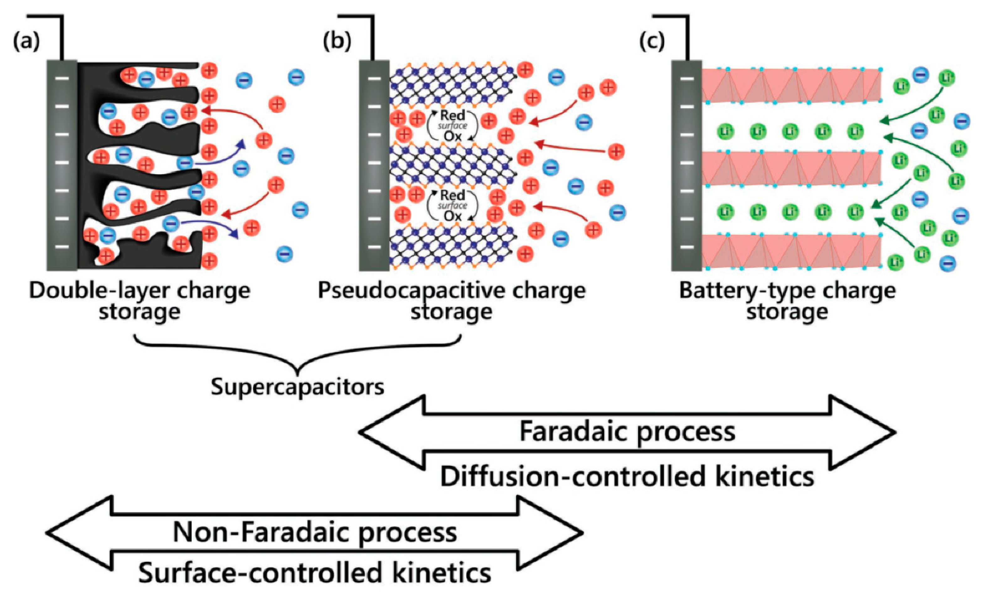
  • In solid electrode materials
This relies on rapid charge separation and/or chemical reactions within the materials, where physical adsorption occurs on the electrode surface, forming an electric double layer (EDL). The energy is stored by flowing the electrolytes through an electrochemical cell system, as in redox flow batteries. Electrical charge can generally be stored in the surface and solid phases of electrodes through various mechanisms, as described below:
  • Double-layer mechanism
This mechanism is primarily electrostatic and non-Faradaic, where charge accumulates at the interface between the electrode and the electrolyte without involving electron transfer or chemical changes in the electrode material, as illustrated in Figure 7a,b.
  • Faradaic process
The transfer of electrons occurs at the electrode–electrolyte interface through surface redox reactions, often accompanied by ion adsorption, as illustrated in Figure 7b,c. For example, activated carbon electrodes’ charge–discharge process primarily arises from charge adsorption or accumulation at the electrode–electrolyte interface, creating an EDL capacitance. This non-Faradaic mechanism involves no chemical reactions in the electrode’s solid phase [45]. In contrast, Faradaic charge storage involves significant pseudocapacitance due to ion adsorption and surface redox reactions. This results in electron transfer across the interface between the current collector and the active material [40,46]. All the mechanisms are recorded and investigated using a three-electrode setup. In the three-electrode setup, the current is applied between the counter (or auxiliary) electrode and the working electrode [46]. As the current flows, the potential of the working electrode changes, and these changes are monitored over time. It is important to note that the current does not pass through the reference electrode, which remains polarized. Instead, the auxiliary electrode applies the desired current to the working electrode. Electrochemical hydrogen storage is governed by two primary mechanisms: adsorption on the surface and insertion into the bulk of the material. The key processes involved in electrochemical hydrogen sorption are the Volmer, Tafel, and Heyrovsky reactions [40,47]. The preliminary step is a charge transfer mechanism that occurs at the electrode–electrolyte interface, represented by the following reactions:
H2O + M + e⁻ ↔ MHads + OH
The Volmer reaction, as described in Reaction 1, involves reducing water to produce hydroxyl ions, with hydrogen atoms being adsorbed onto the surface of the electrode. These adsorbed atoms lead to the formation of subsurface hydrogen (Hss):
MHads ↔ MHss
These hydrogen atoms, which are located beneath the surface, are subsequently diffused into the interior of the material as Habs. Additionally, the Tafel reaction occurs alongside this process, whereby adsorbed hydrogen atoms recombine to form gaseous hydrogen:
2MHads ↔ H2 (g) + 2 M
The Heyrovsky reaction involves the formation of hydrogen molecules through the dissociation of hydrogen atoms from water molecules:
MHads + H2O + e⁻ ↔ M + H2
In electrochemical hydrogen storage, the Volmer reaction is vital and frequently expressed in milliampere hours per gram. In addition, the Heyrovsky and Tafel reactions are examined for hydrogen evolution and production. Figure 8 illustrates a schematic of these three electrochemical reactions involving hydrogen [40,48].
Hydrogen   Storage   Capacity = I × Δ T m × 3600
Equation (6) is used to investigate the electrochemical hydrogen storage capacity according to the discharge time of the prepared electrode. I, ᐃT, and m represent the applied current (mA), discharge time (sec), and mass (g), respectively.
Aghajani et al. [49] synthesized three-dimensional nano-structured nitrogen-doped graphene, which exhibited an excellent electrochemical hydrogen storage capacity of 1916 mAh g−1. They utilized the hydrothermal method for synthesis, combining ammonia in distilled water and graphene oxide solutions. The solution was then poured into an autoclave and hydrothermally processed at 180 °C for 12 h. The electrochemical discharge capacities of the samples were evaluated, revealing that nitrogen doped into graphene oxide resulted in better capacity than graphene oxide without the dopant. Applying current to the working electrode triggered a series of oxidation and reduction reactions, leading to measurable changes in potential. These potential changes were recorded using a reference electrode, which maintained a stable and defined potential. An important equation in the galvanostatic charge–discharge method is the Sand equation, which outlines the connection between the transition time (when the concentration of the oxidizing species drops to zero and the concentration of the reducing species peaks), the concentration of the species being studied, and the applied current [49].
τ 1 2 = n F A C π 1 2 D 1 2 2 i
In Equation (7), the variables τ , F, A, D, C, and i represent the transition time, the number of transition electrons, the Faraday constant, the surface area of the electrode, the diffusion coefficient, the concentration of electroactive species, and the applied current, respectively. The transition time in the electrochemical hydrogen storage process is the endpoint for charging and discharging. The electrochemical hydrogen storage per weight percent was calculated using Equation (8):
C s g = ( H S C × 3.6 × W ) F
where Csg, HSC, W, and F are the capacities of hydrogen stored per formula (H/f.u.), the electrochemical hydrogen storage (mAh g−1), the molar mass of active material (g/f.u.), and the Faraday constant (C/mol).
H ( W t % ) = ( C s g × m ) W
In Equation (8), H(Wt%), Csg, m, and W are the electrochemical hydrogen stored per weight percent, the capacity of hydrogen stored per formula (H/f.u.), the hydrogen atomic weight, and the molar mass. Gholami et al. [50] synthesized a CuO/Al2O3 nanocomposite and investigated the electrochemical hydrogen storage capacity. They evaluated the electrochemical hydrogen capacity of the samples, revealing that higher copper content resulted in better capacity than aluminum content in the nanocomposite. Additionally, the discharge capacity was increased with repeated cycles, rising from 330 mAh g−1 to 6750 mAh g−1, corresponding to 23.9 wt% hydrogen content in the nanocomposite.

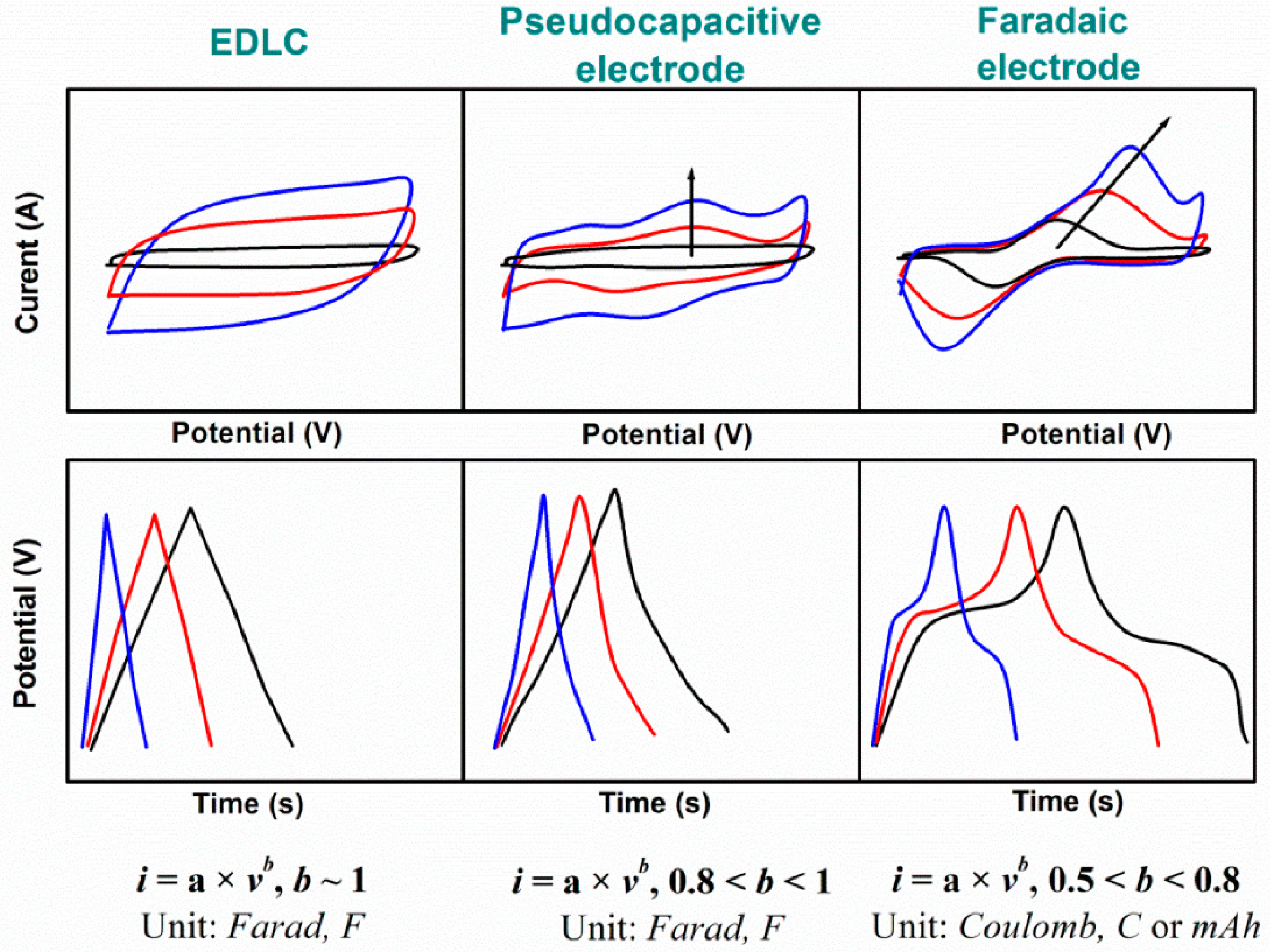
2.1.2. Cyclic Voltammetry

Cyclic voltammetry (CV) is a powerful and popular electrochemical technique that is commonly employed to investigate molecular species’ reduction and oxidation processes. CV is also invaluable in studying electron-transfer-initiated chemical reactions, which include catalysis. The response of the materials is obtained at a particular scan rate in a fixed-potential-window range. The cycles were also repeated to obtain accurate redox peaks. In one direction, the highest observed reduction current indicates the experimental occurrence of hydrogen evolution. Conversely, upon reversing the scan, a peak is noted in the opposite direction, corresponding to the electrochemical process associated with the material’s oxidation. Thus, integrating these peaks gives us the amount of charge stored in the sample. Hence, the oxidation peak directly relates to the hydrogen storage capacity and redox reactions [51]. Equation (9) is used to calculate the specific capacitance from the cyclic voltammetry (CV) results:
C = I d v 2 γ m Δ V
where C shows the specific capacitance (F g−1); I d v is the inside area of the CV curve ( μ A V ); ΔV indicates the applied voltage period; m is the mass of coated active material on nickel foam (mg), and γ indicates the scan rate (mV s−1). Adam et al. [52] synthesized Pd-Cd nanostructures with varying amounts of cadmium. They observed different morphologies that influenced the hydrogen storage capacity of the prepared nanostructures. The cadmium content in these nanostructures ranged from 0% to 20%, and they were synthesized on a titanium substrate using a hydrothermal reduction method. Various morphologies were obtained from these nanostructures. Hydrogen energy storage occurs in these structures because hydrogen typically diffuses into the palladium framework by jumping from one octahedral site to another. This diffusion is enhanced by adding cadmium due to the dilation of the lattice constant. Furthermore, the performance of these nanomaterials for hydrogen adsorption and desorption was evaluated using cyclic voltammetry studies. CV studies were conducted between −200 and 400 mV at a scan rate of 20 mV s−1. The overall quantity of hydrogen storage was assessed by calculating the total integrated area in the anodic region. The maximum hydrogen desorption charge was observed for cadmium within the 10–15% range. As the concentration of Cd increased from 0 to 15%, there was a reduction in the material’s crystalline structure; however, there was a notable increase in the specific surface area, indicating an enhancement in hydrogen sorption.

2.1.3. Electrochemical Impedance Spectroscopy

Electrochemical impedance spectroscopy (EIS) measurements help to identify the electrochemical processes that lead to GCD or CV studies. A key benefit of EIS is that it yields capacitive results, providing important insights into the electrostatic charge storage achieved using this technique. The double-layer capacitance derived from impedance measurements is equivalent to the charging or discharging current of the double layer that is calculated using cyclic voltammetry (CV) within the same voltage range. Specifically, the double-layer current (Idl) can be expressed as the product of double-layer capacitance (Cdl) and the scan rate (V) within the same potential range applied during cyclic voltammetry, as demonstrated in Equation (10). Thus, this double-layer effect is directly associated with the amount of charge that is stored [46].
Idl(E) = Cdl (E) · V
Electrochemical impedance spectroscopy (EIS) is a valuable method for analyzing the interfacial characteristics of electrodes and evaluating electron transfer at the electrode interface. Zhang et al. [53] carried out EIS studies on ordered mesoporous carbon to investigate the electron transfer properties at the electrode interface. Following modifications with nickel, they assessed the charge transfer resistance of various electrodes. The resistance decreased from 12.14 Ω cm2 to 3.61 Ω cm2, indicating that nickel particles enhanced the conductivity of the electrodes and improved their electrochemical hydrogen storage properties. The research conducted by Li et al. [54] is particularly noteworthy, as they examined the high-rate discharge capability of a hybrid assembly electrode composed of a hydrogen storage alloy and reduced graphite oxide. The diffusivity of hydrogen was readily assessed using impedance measurements. Two tests were carried out: one for the basic alloy and another for the hybrid electrode. In both instances, semicircles were detected in the high-frequency area, followed by a linear response in the low-frequency area. The smaller semicircle corresponded to contact resistance, while the larger semicircle was linked to charge transfer resistance. The Warburg impedance was represented by a straight line, indicating the diffusion characteristics. Since the high-rate discharge ability directly depends on charge transfer characteristics, the diffusivity of hydrogen atoms in the electrodes was also assessed. The hydrogen diffusivity for the hydrogen storage alloys/reduced graphene oxide composite electrode (DH = 1.81 × 10⁻¹⁰ cm2 s−1) was greater than that of the alloy electrode (DH = 1.15 × 10⁻¹⁰ cm2 s−1) [54].

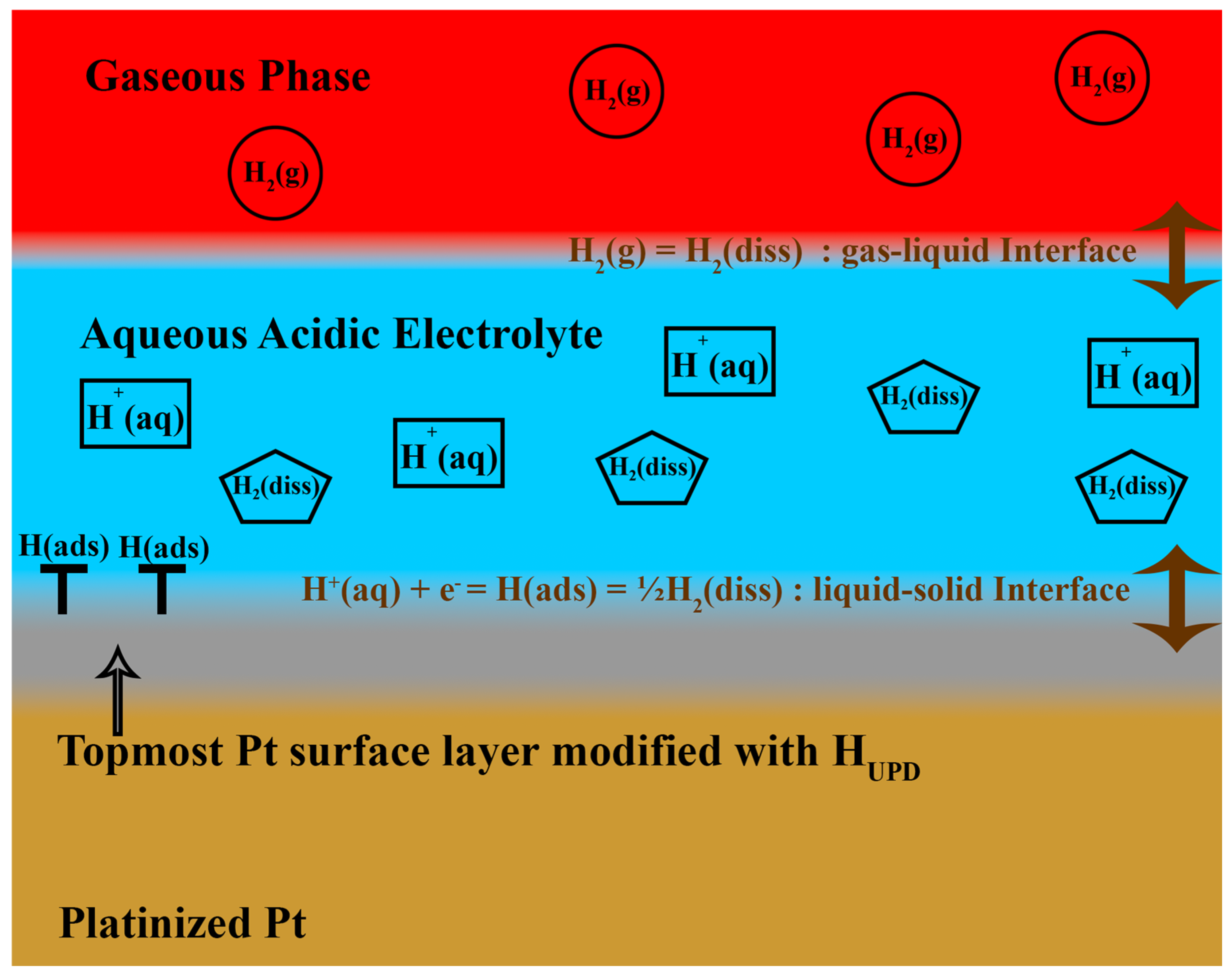
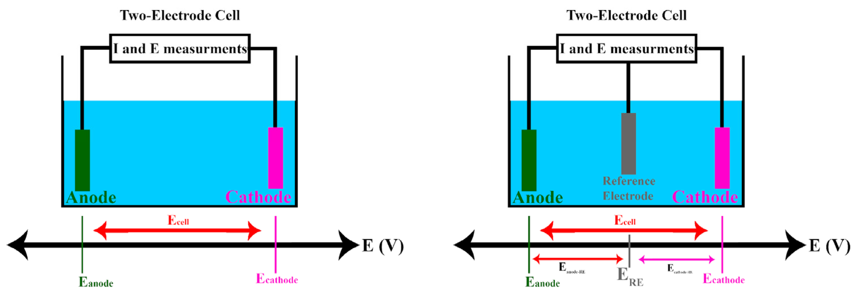
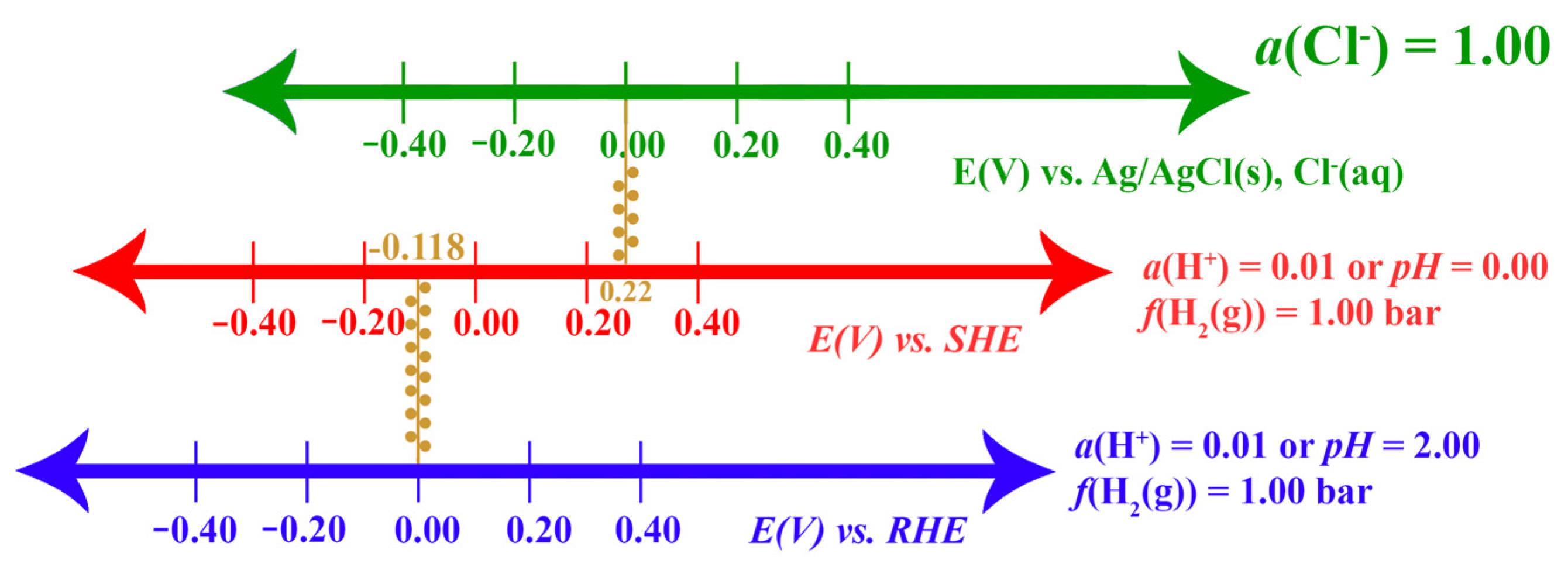
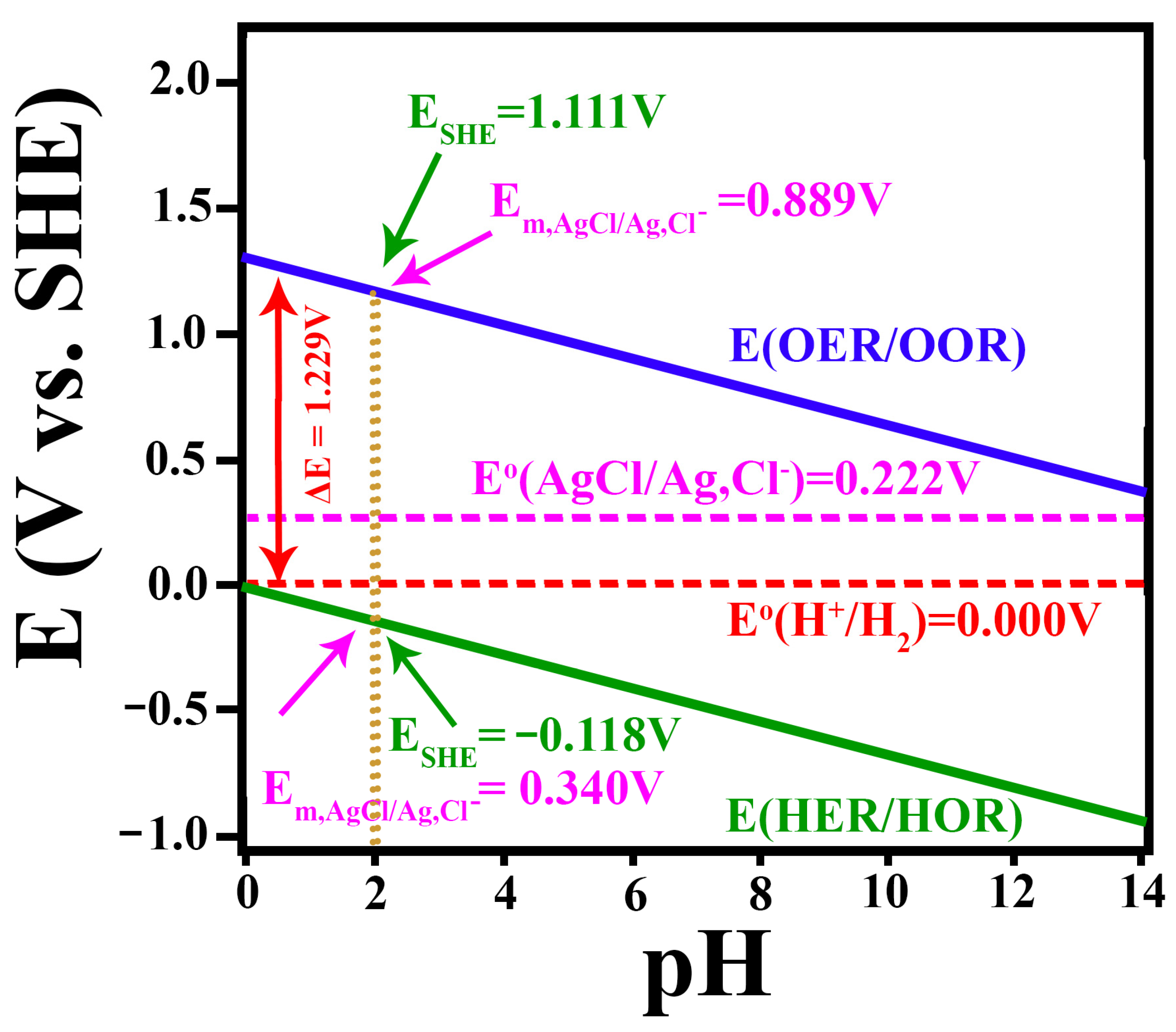
2.1.4. The Standard Hydrogen Electrode and Its Alternative Reference Electrodes

The standard hydrogen electrode in water-based solutions uses a platinum (Pt) electrode coated with fine platinum particles (platinized platinum). This electrode can come in different shapes, such as a mesh, a flat sheet, or a wire. This electrode is immersed in an acid with a unit activity of protons (H+). Hydrogen gas (H2) is supplied at a pressure of 1.00 bar, ideally as tiny bubbles in the solution. This setup ensures that the electrolyte solution quickly becomes saturated with the gas. The following overall equilibrium is established spontaneously at the electrode–electrolyte interface, as shown in Reaction 11:
H + ( aq ) + e 1 2 H 2 ( g )
The platinum (Pt) electrode is essential because it facilitates the dissociation of hydrogen, a crucial step in the overall reaction. In contrast, using another noble metal such as gold is not feasible, as it does not aid in dissociating molecular hydrogen. The Pt’s remarkable activity in the hydrogen evolution reaction (HER), the hydrogen oxidation reaction (HOR), and electrochemical hydrogen storage (EHS) can be attributed to several of its chemical and physical properties, one of which is the underpotential deposition of hydrogen (UPD H).
The layer of underpotential deposited hydrogen (UPD H) on the Pt surface modifies its hydrophilic and hydrophobic characteristics, resulting in weaker interactions between water molecules at the electrolyte–platinum interface and the Pt surface. Research indicates that hydrogen production occurs not on pure Pt but on Pt with a UPD H monolayer. This process is enhanced due to the weaker interactions of water molecules with the Pt surface. Therefore, as depicted in Reaction 12, the overall reaction can also be illustrated, as shown in Figure 9. The final product, H2(diss), may form via the Volmer–Tafel or the Volmer–Heyrovsky mechanism [40].
H + ( aq ) + e H a d s 1 2 H 2 ( d i s s ) 1 2 H 2 ( g )
On the other hand, the standard hydrogen electrode (SHE) is considerably more expensive and challenging to use with various electrolytes and pH levels. As a result, researchers prefer to calculate the range of potential windows using the reversible hydrogen electrode (RHE) as the reference electrode. One of the benefits of the RHE electrode is its versatility, which allows it to be used across a wide range of pH levels. Consequently, RHE electrodes are commonly used as reference electrodes to investigate different active materials. Figure 10 shows a graph of electrode potential (E) versus pH for the H⁺(aq)/H2(g) redox system, with hydrogen gas at a pressure of 1.00 bar and a temperature of 298.15 K. The graph demonstrates that, as pH rises, leading to a decrease in H⁺ concentration, the value of E diminishes by 0.0592 V (or 59.2 mV) for each unit increase in pH. A single point represents the potential of the standard hydrogen electrode (SHE). Concurrently, the orange solid line denotes the zero potential of the reversible hydrogen electrode (RHE) for any specified pH value. The potential difference, ΔE = ERHE − ESHE°, signifies the difference between the blue and black solid lines, defining the RHE’s zero potential in relation to the SHE. It is crucial to understand that the slope of the E versus pH graph is 0.0592 mV per unit of pH only at 298.15 K, as this value is temperature dependent. This detail is crucial when researching temperatures other than 298 K, especially in studies involving various active materials using a three-electrode setup [55].
The reference electrode is utilized in both two-electrode and three-electrode cells. Figure 11 illustrates the two-electrode and three-electrode cells through which the current (I) flows while the cell potential (Ecell) is monitored
In a two-electrode cell consisting of a cathode and an anode, the cell potential is defined by Equation (13). However, it is essential to note that the individual contributions of the cathode potential (Ecathode) and the anode potential (Eanode) to Ecell cannot be directly measured. In contrast, a three-electrode cell includes an additional component—a reference electrode. The cell potential in this setup is also expressed by Equation (7). Adding the reference electrode, whose potential is well defined and known, allows for the cathode and anode potentials to be determined in relation to the reference electrode’s (ERE) potential, as described in Equation (13) [55]:
E c e l l = E c a t h o d e E a n o d e
Different reference electrodes are used in electrochemical and electrocatalysis research, and potential values are often reported relative to these electrodes, but they should always be reported relative to the SHE. This is an essential aspect of electrochemistry and electrocatalysis that may sometimes be overlooked. All experimental potential values must be reported relative to the SHE, including the work function and Fermi level values, which are reported relative to the vacuum-level energy.
The conversion of possible values between different scales and the SHE can be quickly achieved using Equation (14):
E S H E = E m , R E + E R E
In this context, ESHE refers to the potential measured with reference to the standard hydrogen electrode (SHE), while Em,RE denotes the potential measured relative to a reference electrode. ERE represents the reference electrode’s potential (standard or nonstandard) compared to the SHE. Figure 12 compares the potential scales of the standard hydrogen electrode (SHE), the reversible hydrogen electrode (RHE) at a pH of 2.00 with hydrogen gas at 1.00 bar, and the standard silver–silver chloride electrode with a chloride ion activity of 1.00. Figure 12 highlights that the onset potentials for various electrochemical processes, such as the hydrogen evolution reaction/hydrogen oxidation reaction (HER/HOR) and the oxygen evolution reaction/oxygen reduction reaction (OER/ORR), vary significantly across different potential scales [48,55].
The standard potential of the silver–silver chloride electrode (Ag/AgCl) is 0.222 V. In experiments conducted in an acidic aqueous solution with a proton activity (aH+) of 1.00, the potential of the Ag/AgCl electrode can be calculated using the Nernst equation, assuming that the liquid junction potential is negligible, as shown in Equation (15):
E = E ° R T F ln a C l
The standard electrode potential (E°) for the Ag/AgCl electrode is 0.222 V. In the Nernst equation, R is the universal gas constant, T is the temperature in Kelvin, F is the Faraday constant, and aCl represents the activity of chloride ions in the solution. Since the proton activity is 1.00, the pH of the solution is 0, meaning it is highly acidic. However, it is essential to note that the Nernst equation for the Ag/AgCl electrode primarily depends on the activity of chloride ions, and the proton activity does not directly influence the electrode potential. Therefore, to calculate the electrode potential accurately, it is essential to know the activity of chloride ions in the solution [55].
Among the most widely studied electrochemical processes today, various reactions involve ions as either reactants or products. These ions are common to all four reactions and are crucial in operating hydrogen reference electrodes, such as the standard hydrogen electrode (SHE) and the reversible hydrogen electrode (RHE). These reference electrodes are particularly suitable for studying the mechanisms and kinetics of these reactions. The SHE is frequently used as a reference in experimental studies. However, when the concentration or composition of the electrolyte in the working electrode (WE) chamber differs from that in the SHE chambers, a potential known as the liquid junction potential (Elj) appears. Although this potential can be eliminated using a salt bridge, doing so complicates the experimental setup. The reversible hydrogen electrode (RHE) is simpler and more practical when the working electrode (WE) and reference electrode (RE) chambers contain the same aqueous electrolyte, whether acidic or alkaline. It is important to note that the zero potential of the RHE can shift from its standard value (on the SHE scales) when the activity of the ions deviates from unity [48]. In an acidic aqueous electrolyte with a pH of 2.00, the onset potentials for the hydrogen evolution reaction (HER), hydrogen oxidation reaction (HOR), oxygen evolution reaction (OER), and oxygen reduction reaction (ORR) were examined using different reference electrodes. Figure 13 is established as follows:
  • Using the reversible hydrogen electrode (RHE):
The onset potentials are 0.00 V for HER/HOR and 1.23 V for OER/ORR.
  • Using the standard hydrogen electrode (SHE):
If the liquid junction potential is eliminated, the onset potentials shift to −0.118 V for HER/HOR and 1.111 V for OER/ORR.
  • Using the silver–silver chloride electrode (Ag/AgCl):
Under the same conditions, the onset potentials are −0.340 V for HER/HOR and 0.889 V for OER/ORR.
Variations in onset potentials underscore the importance of considering the reference electrode used when interpreting electrochemical data. Converting potentials to a common reference, such as the standard hydrogen electrode (SHE), facilitates consistent comparisons across different studies. When using reference electrodes other than SHE, it is crucial to accurately convert potential values to the reversible hydrogen electrode (RHE) or SHE scale. This ensures that the reported potentials and overpotentials are correct, preventing errors. This analysis is a valuable guide for comparing reference electrodes and accurately interpreting experimental results in electrochemical reactions [15,55].

3. Carbon Materials for Hydrogen Storage

3.1. Carbon Active

Pursuing high-performance hydrogen storage materials is still crucial to advancing hydrogen-based clean energy solutions and has been the focus of extensive attention for decades. Various storage media have been developed to meet the strict demands of rapid hydrogen adsorption/desorption, stable thermodynamics, lightweight properties, an extended cycle life, and cost-effectiveness. Among the different materials that have been explored, carbon-based materials have remarkable features for this purpose. Carbon materials such as carbon nanotubes (CNT), reduced graphene oxide (r-GO), graphite, and graphene foam (GF) have been evaluated for their hydrogen storage capacity through extensive studies. The potential of an electrochemical valve was demonstrated by Qu’s research; it effectively retains hydrogen within the carbon structure during storage and prevents leakage [17,56,57,58]. The cost-effectiveness, excellent conductivity, high strength-to-weight ratio, low density, chemical stability, and high heat resistance of carbon materials make them ideal for electrochemical hydrogen storage applications. Their versatile bonding capabilities make carbon nanotubes, nanofibers, fullerenes, and graphene attractive for hydrogen storage, among carbon materials [59,60,61]. Reaction 16 summarizes the mechanism of hydrogen absorption/desorption in carbon materials:
C + n H 2 O + n e C H n + n O H
The equation reveals that hydrogen produced through water reduction is adsorbed onto the carbon host under an applied potential. When the potential is removed, the host material releases the absorbed hydrogen, which reacts with hydroxide ions (OH) to form water. By polarizing under applied potential, the defects and wrinkles in graphene enhance the absorption of H atoms. Furthermore, regarding the adsorption of H, the electrochemical properties of energy storage materials significantly depend on their sizes, morphologies, and structures. Over recent decades, diverse morphologies have been synthesized, including platelets, rods, wires, belts, and hierarchical flower-like architectures. Among these, the hierarchical flower-like architecture, with its relatively high specific surface area, shortened diffusion lengths, and improved volume-change accommodation, holds promise for electrochemical energy storage applications. Efforts have been directed towards synthesizing hierarchical architectures: notably, hierarchical Co metal structures, which are expected to enhance electrochemical kinetics, cycle stability, and hydrogen storage capacity [50,51,52,53]. This hierarchical architecture enhances the specific surface area, shortens the diffusion length of the adsorbed hydrogen, and effectively accommodates volume changes during charge–discharge cycles, resulting in improved hydrogen storage capacity, cycle stability, and discharge rate capabilities [57,62,63,64,65].
In the meantime, the inclusion of metal nanoparticles on the surface of carbon materials has been observed to significantly enhance the kinetics of hydrogen intercalation through a phenomenon known as the spillover effect. Additionally, introducing heteroatoms via doping has emerged as a crucial factor influencing the performance of electrochemical hydrogen storage. Recent reports highlight that metal nanoparticles exhibit outstanding hydrogen storage capabilities, including rapid activation rates and high reversibility. Reactions 17–20 show the reactions that happen in an acid medium to store hydrogen protons step by step [66,67]:
H 3 O + + e H + H 2 O
H 2 O + e H + OH
C + H C H a d s C H s t o r e
C H s t o r e e H + + C
Research conducted by Zhou et al. [68] investigated the electrochemical hydrogen storage performance of nitrogen-doped uniform microporous carbon, demonstrating its exceptional hydrogen storage capabilities. According to Liu et al., a 1.5-fold enhancement in electrochemical hydrogen insertion was observed in nitrogen-doped carbon electrodes in ordered mesoporous carbon [69]. A study conducted by Fang et al. explored the electrochemical hydrogen storage performance of carbon pores within a specific range (2.1–2.8 nm) [70]. It emphasized the significance of ultra-micro pores (<0.7 nm) in hydrogen storage. Zhang et al. [57] employed electrochemical carbon materials to fabricate a hydrogen ion supercapacitor battery. The electrolyte they used was a 30% KOH solution [41,71,72,73].
The surface area of the microporous carbon (MIC) and nitrogen-doped microporous carbon (N-MIC) samples was measured using the Brunauer–Emmett–Teller (BET) method and was found to be 2116.95 m2 g−1 and 1752.42 m2 g−1, respectively. Cyclic voltammograms (CVs) and charge–discharge curves were generated for the microporous carbon MIC, the mesoporous carbon (MEC), and the macroporous carbon (MAC), with all CVs conducted at a scanning speed of 20 mV s−1 within a potential range of −1.1 V to 0.2 V. These profiles showed that all three carbon samples exhibited similar CV profiles. Still, the capacity of MIC exceeded that of MEC and MAC. It is important to note that, during the final charging step, hydrogen intercalation into the carbon continued competing with the hydrogen evolution reaction (HER), leading to decreased coulombic efficiency. The discharge curves demonstrated a decreasing order of electrochemical hydrogen storage capacities among the three carbon types: MIC (85.8 mAh g−1), MEC (61.3 mAh g−1), and MAC (52.1 mAh g−1). This highlights a strong correlation between surface area, the porous nanostructure of carbon, and the electrochemical hydrogen storage capacity. Furthermore, variations in the scan rate influenced the cathodic current, encompassing hydrogen production and absorption, and the anodic current, including hydrogen desorption, at the electrode and electrolyte interface. A larger width indicated higher hydrogen storage levels. Hence, due to its higher specific surface area, the synthesized graphene oxide (GO) layer exhibited superior electrochemical hydrogen storage capabilities compared to carbon materials [41,57,70,71,72,73]. Table 1 shows the maximum discharge capacity of electrochemical hydrogen storage using various carbon-based materials and three-dimensional graphene foam as the active material.

3.2. Graphene and Graphene Oxide and Their Properties

Graphene, an ultrathin, two-dimensional (2D) sheet composed of sp2 carbon atoms, represents a groundbreaking addition to the family of carbonaceous materials. Its outstanding electrical, optical, and mechanical characteristics have ignited significant interest in the research community over the past decade. With a vast surface area of 2630 m2 g−1 and exceptional porosity, graphene is an ideal candidate for applications involving gas adsorption and electrochemical hydrogen storage. It boasts impressive attributes, including a high surface area (2630 m2 g−1) [80], a Young’s modulus of 1 TPa [81], a fracture strength of 130 GPa [81], and remarkable thermal (5 W m K−1) [82] and electrical (720 S m−1) conductivity [63].
Graphene, however, faces a challenge in the form of stacking behavior, which undermines some of its unique properties [80,81]. Nonetheless, graphene has captivated the global scientific community; this attention is driven by its single-atom thickness, flexible two-dimensional structure, and extraordinary physical and chemical attributes [82,83]. Extensive research has revealed graphene’s immense potential in various technological domains, spanning from field-effect devices to chemical and biological sensors, energy storage materials, polymer composites, electrocatalysis, and electrochemical hydrogen storage [84,85,86]. Its unique structure and properties have also fascinated researchers. GO comprises carbon atoms bonded together and decorated with different oxygen-containing functional groups. The upper and lower basal planes are decorated with hydroxyl and carbonyl groups, while the edges are adorned with carboxyl groups [87]. These functional groups make GO highly attractive to water, allowing it to easily mix with water as single sheets, creating a uniform dispersion. GO is also an interfacial connector, facilitating stress transfer from polymers to GO. Extensive studies have confirmed the substantial enhancement of thermal stability, mechanical properties, and electrical conductivity in GO-reinforced polymers, which is primarily attributed to GO’s high aspect ratio, robustness, high Young’s modulus, and robust interfacial interactions with polymers [88]. Figure 14 shows a schematic diagram for synthesizing graphene oxide from graphite using Hammer’s method.

3.3. Three-Dimensional (3D) Graphene Foam

Scientists have developed a revolutionary three-dimensional (3D) porous structure called graphene foam (GF) to counteract graphene’s stacking tendency and unlock its full potential. Graphene foam features a porous configuration with interconnected networks of pores [49,90]. This unique morphology establishes efficient pathways for electron transfer, endowing it with exceptional electrical conductivity. A large specific surface area, a low density, the lightweight nature, and an impressive strength-to-weight ratio are among the distinguishing attributes of graphene foam [64,65,91]. Various methods have been devised to synthesize 3D graphene foam, including chemical vapor deposition onto nickel foam and hydrothermal techniques. The hydrothermal approach entails the formation of 3D graphene foam through π–π stacking between graphene sheets, in conjunction with residual oxygenated functional groups on reduced GO sheets. These residual hydrophilic groups enable reduced GO sheets to encapsulate water during self-assembly. This, coupled with the stacking of graphene sheets, results in the successful construction of graphene foam [92]. The arrangement of sp2 hybridized carbon atoms in a honeycomb crystal lattice gives rise to 3D graphene foam, pushing the boundaries of advanced materials. Zero-dimensional fullerenes, one-dimensional carbon nanotubes, and three-dimensional graphene foam stem from graphene, their foundational building block. Due to their unprecedented physical and chemical properties, extensive research has been conducted on their use in nanoelectronics, sensors, batteries, supercapacitors, hydrogen storage, and nanocomposites [64].
Three-dimensional (3D) graphene structures, including hydrogels, aerogels, cokes, foams, and sponges, have become favored in numerous scientific domains, particularly electronics and hydrogen storage, as illustrated in Figure 15. These structures combine the exceptional properties of graphene with 3D macroscopic material characteristics, presenting myriad advantages in materials science. Their inherent combination of high mechanical strength and flexibility enables their application in electronic devices requiring the application of pressure. Additionally, their lightweight nature makes them suitable for portable and wearable technologies. Moreover, 3D graphene foam composites, which are characterized by high electrical conductivity, are frequently employed as catalysts across various fields. The interconnected graphene network within these structures facilitates the transfer of electrons and ions, simplifying transport processes. Introducing heteroatoms such as nitrogen (N), boron (B), phosphorus (P), and sulfur (S) into carbon materials through doping has proven effective in modifying the electronic and catalytic properties of the carbon host. These 3D N-doped graphene foams exhibit potential as carbon composite catalysts in applications such as fuel cells, batteries, supercapacitors, electrochemical hydrogen storage, and various catalytic reactions. Dopants can also affect the strength of 3D graphene foam [85,86,87,88]. The strength of 3D graphene foam can vary greatly depending on its density. When the foam is very light (1.5 mg/cm3), it can hold up to 11 kPa of force before breaking. When it is much denser (110 mg/cm3), it can handle up to 11 MPa. In another study, a similar material called reduced graphene oxide (rGO) foam was found to have a strength of 3.2 MPa. Its stiffness, measured according to Young’s modulus, ranged between 7 MPa and 40 MPa as it was stretched and tested.
The 3D structure emerges from in-plane and out-of-plane orientations at the junction of the branches, contributing to the material’s mechanical robustness. Research conducted by Yocham et al. determined the porosity of graphene foam to be an impressive 86.7%. These hollow tunnels within the interconnected layers of graphene foam enable it to exhibit mechanical strength capable of withstanding loads 50,000 times its weight. The material’s mechanical strength further benefits from reduced defects and denser branching within the 3D graphene monolith [78,93].
Additionally, when integrated with graphene foam structures, polymer composites, such as epoxy, polyvinyl alcohol (PVA), polydimethylsiloxane (PDMS), polyaniline (PANI), polypyrrole (PPy), polymethyl methacrylate (PMMA), polystyrene (PS), polyurethane (PU), polyvinylidene fluoride (PVDF), and polyimide (PI), reinforce the resulting material’s mechanical properties, as illustrated in Figure 16 [94,95]. The strength of 3D graphene foam and the specific surface are effective parameters. A higher specific surface can increase the absorption of ions onto the surface [78].
Charge–discharge tests were conducted using a KOH solution at room temperature with various currents applied to determine this parameter [37,41]. Multiple factors, including the hydrogen adsorption properties of GO, the morphology of the foam substrate, the applied current, and electrolyte molarity, were found to influence the hydrogen storage capacity. The circular shape of the porosities facilitated the overlapping of GO nanoparticles on the substrate’s surface, leading to nanoparticle aggregation at the edges, a phenomenon previously reported by Wang et al. [17]. This study’s synthesized porous 3D graphene structure possessed two distinct characteristics: a porous framework with a high surface area and a defective structure. It is well established that porous structures with a high surface area readily adsorb hydrogen. The host material can adsorb hydrogen ions through Van der Waals forces, providing more active sites for hydrogen ion storage [95]. At a deeper level, the defects in graphene layers, including edges, dangling bonds, and unsaturated sp2/sp3 carbons, served as active sites for hydrogen chemisorption, forming C–H bonds. These chemisorbed hydrogens were found to be reversible. Oxygen functional groups can block these active sites, reducing hydrogen uptake capacity. The proposed mechanism for hydrogen chemisorption is further elaborated below [81,96]. Table 2 provides an overview of the synthesis techniques employed for producing 3D graphene foam.
When exposed to an electric potential, carbon atoms at active sites became polarized and strongly attracted to hydrogen atoms [106]. Additionally, applying an electric field resulted in potential asymmetry between the layers of graphene, resulting in a band gap between microscopic polarizations and the lower energy bands. This interlayer polarization was further enhanced by wrinkles resulting from the mismatch of the graphene sheets, thereby facilitating hydrogen atom adsorption [106]. Cyclic voltammetry (CV) has become a prominent technique for elucidating the mechanisms behind electrochemical reactions, emphasizing the peaks corresponding to reduction and oxidation. Within the Volmer reaction framework, the transfer of electrons can lead to the generation of OH⁻ ions. The resulting hydrogen atoms can then be adsorbed onto the surface of graphene nanosheets, which form the walls of the porous structure. During the charging process, hydrogen evolution may take place. When specific conditions are met, the adsorbed hydrogen atoms can take a reverse route and recombine to produce hydrogen molecules [96]. The formation of molecular hydrogen becomes possible through the following reactions:
C H a d s + H 2 O + e H 2 + O H + C
H + H H 2
C H a d s + C H a d s H 2 + 2 C
If the energy released during these reactions exceeded the energy released during hydrogen adsorption, and if the activation energy for at least one of these reactions could be easily overcome, then the adsorbed hydrogen atoms recombined. In cases where recombination did not occur, the adsorbed hydrogen atoms diffused into the bulk of the graphene foam, occupying active sites with higher adsorption energies. During the discharge stage, hydrogen atoms diffused from inner regions to the electrode’s surface, donating electrons to carbon and combining with OH⁻ ions to generate H2O [95,107,108,109,110,111].

4. Prospects and Future Directions

In the future, scientists should explore how 3D graphene foam can be used to efficiently store hydrogen, as well as consider its important role in developing sustainable energy solutions. In recent years, electrochemical hydrogen storage has witnessed significant advancements, and 3D graphene foam has emerged as a frontrunner in this technological evolution. Its remarkable properties, including its high surface area, excellent electrical conductivity, and exceptional mechanical strength, make it an ideal candidate for storing and releasing hydrogen gas efficiently and safely. These qualities and their inherent environmental friendliness underscore the incredible promise that 3D graphene foam holds. Our ongoing research efforts are not merely incremental; they are transformative. We are committed to pushing the boundaries of what this material can achieve. Researchers worldwide are dedicated to improving the performance of 3D graphene foam in terms of hydrogen storage capacity, durability, and cost-effectiveness. Additionally, refining production techniques to scale up its manufacturing and accessibility is a central focus. As a result, we are steadily moving closer to unlocking the full potential of 3D graphene foam for practical applications. The transformative potential of 3D graphene foam extends beyond its immediate applications in energy storage. It is poised to play a pivotal role in addressing critical global challenges, such as the transition to renewable energy sources and climate change mitigation. Its ability to efficiently store and release hydrogen gas could revolutionize the energy landscape by providing a clean, reliable, and versatile energy carrier. Moreover, the eco-friendly nature of graphene foam aligns perfectly with the growing emphasis on sustainability and environmental responsibility. Hope and innovation are symbolized by 3D graphene foam in the complex network of energy transitions. By deploying it in energy storage systems, we can decrease our dependence on fossil fuels, reduce greenhouse gas emissions, and contribute to a cleaner, more sustainable future. Furthermore, this material can generate new opportunities and industries, propelling economic expansion while promoting environmental preservation. As we continue to explore and harness the unique properties of 3D graphene foam, we are on the verge of a technological breakthrough. Moreover, we are on the brink of a significant shift in society. Hydrogen-based energy solutions, empowered by materials including 3D graphene foam, can bring about a brighter, greener, and more energy-efficient future. A world with sustainable energy is envisioned through science, engineering, and environmental responsibility.

Funding

This research was funded by AGH University of Krakow from the IDUB project nr. 6438.

Institutional Review Board Statement

Not applicable.

Informed Consent Statement

Not applicable.

Data Availability Statement

No new data were created or analyzed in this study.

Conflicts of Interest

The authors declare no conflicts of interest.

References

  1. Zhang, S.; Peng, S.; Hu, R.; Ramakrishna, S. Copper Vanadates/Polyaniline Composites as Anode Materials for Lithium-Ion Batteries. RSC Adv. 2015, 5, 20692–20698. [Google Scholar] [CrossRef]
  2. Ghorbani, R.; Behrangi, S.; Aghajani, H.; Taghizadeh Tabrizi, A.; Abdian, N. Application of Synthesized Porous 3D Graphene Structure for Electrochemical Hydrogen Storage. Mater. Sci. Eng. B 2021, 268, 115139. [Google Scholar] [CrossRef]
  3. Ghiyasiyan-Arani, M.; Salavati-Niasari, M. Decoration of green synthesized S, N-GQDs and CoFe2O4 on halloysite nanoclay as natural substrate for electrochemical hydrogen storage application. Sci. Rep. 2022, 12, 8103, Erratum: Sci. Rep. 2022, 12, 13241. [Google Scholar]
  4. Zhang, Y.; Feng, D.; Sun, H.; Bu, W.; Qi, Y.; Guo, S. Structure and Electrochemical Hydrogen Storage Characteristics of Ce-Mg-Ni-Based Alloys Synthesized by Mechanical Milling. J. Rare Earths 2017, 35, 280–289. [Google Scholar] [CrossRef]
  5. Hren, R.; Vujanović, A.; Van Fan, Y.; Klemeš, J.J.; Krajnc, D.; Čuček, L. Hydrogen Production, Storage and Transport for Renewable Energy and Chemicals: An Environmental Footprint Assessment. Renew. Sustain. Energy Rev. 2023, 173, 113113. [Google Scholar] [CrossRef]
  6. Zhang, H.; Fu, X.; Yin, J.; Zhou, C.; Chen, Y.; Li, M.; Wei, A. The Effect of MWNTs with Different Diameters on the Electrochemical Hydrogen Storage Capability. Phys. Lett. Sect. A Gen. At. Solid State Phys. 2005, 339, 370–377. [Google Scholar] [CrossRef]
  7. Eftekhari, A.; Fang, B. Electrochemical Hydrogen Storage: Opportunities for Fuel Storage, Batteries, Fuel Cells, and Supercapacitors. Int. J. Hydrogen Energy 2017, 42, 25143–25165. [Google Scholar] [CrossRef]
  8. Alinavaz, S.; Ghiyasiyan-Arani, M.; Salavati-Niasari, M. Electrochemical Hydrogen Storage Capacities of Sol-Gel Synthesized Dy3Fe5O12/DyFeO3 Nanocomposites: Schiff-Base Ligand-Assisted Synthesis and Characterization. Fuel 2022, 324, 124600. [Google Scholar] [CrossRef]
  9. Rubio-Saavedra, D.; Zagal-Padilla, C.K.; Bustos-Terrones, V.; Shirley-Irazoque; Gamboa, S.A. An Insight into the Electrochemical Charge/Discharge Process of Ceramic Hydride Electrodes for Battery Applications. Int. J. Hydrogen Energy 2022, 47, 30225–30233. [Google Scholar] [CrossRef]
  10. Bhat, K.S.; Nagaraja, H.S.S. Electrochemical Hydrogen-Storage Performance of Copper Sulfide Micro-Hexagons. Int. J. Hydrogen Energy 2021, 46, 5530–5536. [Google Scholar] [CrossRef]
  11. Salehabadi, A.; Dawi, E.A.; Sabur, D.A.; Al-Azzawi, W.K.; Salavati-Niasari, M. Progress on Nano-Scaled Alloys and Mixed Metal Oxides in Solid-State Hydrogen Storage; an Overview. J. Energy Storage 2023, 61, 106722. [Google Scholar] [CrossRef]
  12. Shang, Y.; Zhang, D.; An, M.; Li, Z. Enhanced Thermal Performance of Composite Phase Change Materials Based on Hybrid Graphene Aerogels for Thermal Energy Storage. Materials 2022, 15, 5380. [Google Scholar] [CrossRef] [PubMed]
  13. Tuluhong, A.; Chang, Q.; Xie, L.; Xu, Z.; Song, T. Current Status of Green Hydrogen Production Technology: A Review. Sustainability 2024, 16, 9070. [Google Scholar] [CrossRef]
  14. Owais, M.; Shiverskii, A.; Pal, A.K.; Mahato, B.; Abaimov, S.G. Recent Studies on Thermally Conductive 3D Aerogels/Foams with the Segregated Nanofiller Framework. Polymers 2022, 14, 4796. [Google Scholar] [CrossRef]
  15. Kaur, M.; Pal, K. Potential Electrochemical Hydrogen Storage in Nickel and Cobalt Nanoparticles-Induced Zirconia-Graphene Nanocomposite. J. Mater. Sci. Mater. Electron. 2020, 31, 10903–10911. [Google Scholar] [CrossRef]
  16. Wei, T.Y.; Lim, K.L.; Tseng, Y.S.; Chan, S.L.I.I. A Review on the Characterization of Hydrogen in Hydrogen Storage Materials. Renew. Sustain. Energy Rev. 2017, 79, 1122–1133. [Google Scholar] [CrossRef]
  17. Chen, P.; Yang, J.J.; Li, S.S.; Wang, Z.; Xiao, T.Y.; Qian, Y.H.; Yu, S.H. Hydrothermal Synthesis of Macroscopic Nitrogen-Doped Graphene Hydrogels for Ultrafast Supercapacitor. Nano Energy 2013, 2, 249–256. [Google Scholar] [CrossRef]
  18. Esfahani, M.H.; Zinatloo-Ajabshir, S.; Naji, H.; Marjerrison, C.A.; Greedan, J.E.; Behzad, M. Structural Characterization, Phase Analysis and Electrochemical Hydrogen Storage Studies on New Pyrochlore SmRETi2O7 (RE = Dy, Ho, and Yb) Microstructures. Ceram. Int. 2023, 49, 253–263. [Google Scholar] [CrossRef]
  19. Rezayeenik, M.; Mousavi-Kamazani, M.; Zinatloo-Ajabshir, S. CeVO4/RGO Nanocomposite: Facile Hydrothermal Synthesis, Characterization, and Electrochemical Hydrogen Storage. Appl. Phys. A Mater. Sci. Process. 2023, 129, 47. [Google Scholar] [CrossRef]
  20. Wei, Y.; Xu, C.; He, G.; Hua, R.; Xie, Z.; Liu, D.; Li, X.; Zhang, R.; Tang, H.; Li, J.; et al. Influence of Structural and Chemical Environmental Factors on Electrochemical Hydrogen Storage in Carbon Materials. Electrochim. Acta 2022, 433, 141223. [Google Scholar] [CrossRef]
  21. Yousefi Bonab, S.S.; Kouzehgar, H.; Taghizadeh Tabrizi, A.; Aghajani, H. Assessment of the Effect of Electrophoretic Deposition Parameters on Hydrogen Storage Performance of Graphene Oxide Layer Applied on Nickel Foam. Int. J. Hydrogen Energy 2022, 47, 2491–2499. [Google Scholar] [CrossRef]
  22. Skowroński, J.M.; Urbaniak, J. Nickel Foam/Polyaniline-Based Carbon/Palladium Composite Electrodes for Hydrogen Storage. Energy Convers. Manag. 2008, 49, 2455–2460. [Google Scholar] [CrossRef]
  23. Cui, P.; Bao, Z.; Liu, Y.; Zhou, F.; Lai, Z.; Zhou, Y.; Zhu, J. Corrosion Behavior and Mechanism of Dual Phase Fe1.125Ni1.06CrAl High Entropy Alloy. Corros. Sci. 2022, 201, 110276. [Google Scholar] [CrossRef]
  24. Khoshnevisan, B.; Behpour, M.; Shoaei, S. Enhancement of Hydrogen Storage by Electrophoresis Deposition of CNTs into Nanoscale Pores of Silver Foams. Int. J. Hydrogen Energy 2012, 37, 2298–2303. [Google Scholar] [CrossRef]
  25. Gómez, J.A.; Santos, D.M.F. The Status of On-Board Hydrogen Storage in Fuel Cell Electric Vehicles. Designs 2023, 7, 97. [Google Scholar] [CrossRef]
  26. Wang, Y.; Deng, W.; Liu, X.; Wang, X. Electrochemical Hydrogen Storage Properties of Ball-Milled Multi-Wall Carbon Nanotubes. Int. J. Hydrogen Energy 2009, 34, 1437–1443. [Google Scholar] [CrossRef]
  27. Zhang, C.; Li, J.; Liu, E.; He, C.; Shi, C.; Du, X.; Hauge, R.H.; Zhao, N. Synthesis of Hollow Carbon Nano-Onions and Their Use for Electrochemical Hydrogen Storage. Carbon N. Y. 2012, 50, 3513–3521. [Google Scholar] [CrossRef]
  28. Liu, E.; Wang, J.; Li, J.; Shi, C.; He, C.; Du, X.; Zhao, N. Enhanced Electrochemical Hydrogen Storage Capacity of Multi-Walled Carbon Nanotubes by TiO2 Decoration. Int. J. Hydrogen Energy 2011, 36, 6739–6743. [Google Scholar] [CrossRef]
  29. Gao, P.; Chen, Y.; Lv, H.; Li, X.; Wang, Y.; Zhang, Q. Synthesis of CuO Nanoribbon Arrays with Noticeable Electrochemical Hydrogen Storage Ability by a Simple Precursor Dehydration Route at Lower Temperature. Int. J. Hydrogen Energy 2009, 34, 3065–3069. [Google Scholar] [CrossRef]
  30. Qu, D.; Xu, X.; Zhou, L.; Li, W.; Wu, J.; Liu, D.; Xie, Z.Z.; Li, J.; Tang, H. Electrochemical Hydrogen Storage in Iron–Nitrogen Dual-Doped Ordered Mesoporous Carbon. Int. J. Hydrogen Energy 2019, 44, 7326–7336. [Google Scholar] [CrossRef]
  31. Sharma, S.; Agarwal, S.; Jain, A. Significance of Hydrogen as Economic and Environmentally Friendly Fuel. Energies 2021, 14, 7389. [Google Scholar] [CrossRef]
  32. Xie, L.; Li, X.Q. Study on Electrochemical Hydrogen Storage of Multi-Walled Carbon Nanotubes. Adv. Mater. Res. 2007, 24–25, 831–834. [Google Scholar] [CrossRef]
  33. Young, K.H.; Nei, J. The Current Status of Hydrogen Storage Alloy Development for Electrochemical Applications. Materials 2013, 6, 4574–4608. [Google Scholar] [CrossRef]
  34. Yang, C.C.; Li, Y.J.; Chen, W.H. Electrochemical Hydrogen Storage Behavior of Single-Walled Carbon Nanotubes (SWCNTs) Coated with Ni Nanoparticles. Int. J. Hydrogen Energy 2010, 35, 2336–2343. [Google Scholar] [CrossRef]
  35. Hu, P.; Cao, Y.; Lu, B. Flowerlike Assemblies of Bi2S3 Nanorods by Solvothermal Route and Their Electrochemical Hydrogen Storage Performance. Mater. Lett. 2013, 106, 297–300. [Google Scholar] [CrossRef]
  36. Kaur, M.; Pal, K. Synthesis, Characterization and Electrochemical Evaluation of Hydrogen Storage Capacity of Graphitic Carbon Nitride and Its Nanocomposites in an Alkaline Environment. J. Mater. Sci. Mater. Electron. 2021, 32, 12475–12489. [Google Scholar] [CrossRef]
  37. Okhay, O.; Tkach, A. Graphene/Reduced Graphene Oxide-Carbon Nanotubes Composite Electrodes: From Capacitive to Battery-Type Behaviour. Nanomaterials 2021, 11, 1240. [Google Scholar] [CrossRef]
  38. Fang, B.; Zhou, H.; Honma, I. Ordered Porous Carbon with Tailored Pore Size for Electrochemical Hydrogen Storage Application. J. Phys. Chem. B 2006, 110, 4875–4880. [Google Scholar] [CrossRef]
  39. Liu, P.; Lee, S.H.; Edwin Tracy, C.; Turner, J.A.; Pitts, J.R.; Deb, S.K. Electrochromic and Chemochromic Performance of Mesoporous Thin-Film Vanadium Oxide. Solid State Ionics 2003, 165, 223–228. [Google Scholar] [CrossRef]
  40. Masjedi-Arani, M.; Salavati-Niasari, M. Novel Synthesis of Zn2GeO4/Graphene Nanocomposite for Enhanced Electrochemical Hydrogen Storage Performance. Int. J. Hydrogen Energy 2017, 42, 17184–17191. [Google Scholar] [CrossRef]
  41. Ren, L.; Hui, K.S.N.; Hui, K.S.N.; Liu, Y.; Qi, X.; Zhong, J.; Du, Y.; Yang, J. 3D Hierarchical Porous Graphene Aerogel with Tunable Meso-Pores on Graphene Nanosheets for High-Performance Energy Storage. Sci. Rep. 2015, 5, 1–12. [Google Scholar] [CrossRef] [PubMed]
  42. Amani, H.; Mostafavi, E.; Arzaghi, H.; Davaran, S.; Akbarzadeh, A.; Akhavan, O.; Pazoki-Toroudi, H.; Webster, T.J. Three-Dimensional Graphene Foams: Synthesis, Properties, Biocompatibility, Biodegradability, and Applications in Tissue Engineering. ACS Biomater. Sci. Eng. 2019, 5, 193–214. [Google Scholar] [CrossRef] [PubMed]
  43. Salarizadeh, P.; Rastgoo-Deylami, M.; Askari, M.B.; Hooshyari, K. A Short Review on Transition Metal Chalcogenides/Carbon Nanocomposites for Energy Storage. Nano Futur. 2022, 6, 032005. [Google Scholar] [CrossRef]
  44. Mathis, T.S.; Kurra, N.; Wang, X.; Pinto, D.; Simon, P.; Gogotsi, Y. Energy Storage Data Reporting in Perspective—Guidelines for Interpreting the Performance of Electrochemical Energy Storage Systems. Adv. Energy Mater. 2019, 9, 1902007. [Google Scholar] [CrossRef]
  45. Leng, J.; Mei, H.; Zhan, L.; Wang, Y.; Yang, S.; Song, Y. V2O3 Nanoparticles Anchored onto the Reduced Graphene Oxide for Superior Lithium Storage. Electrochim. Acta 2017, 231, 732–738. [Google Scholar] [CrossRef]
  46. Liao, Y.; Huang, Y.; Shu, D.; Zhong, Y.; Hao, J.; He, C.; Zhong, J.; Song, X. Three-Dimensional Nitrogen-Doped Graphene Hydrogels Prepared via Hydrothermal Synthesis as High-Performance Supercapacitor Materials. Electrochim. Acta 2016, 194, 136–142. [Google Scholar] [CrossRef]
  47. Deng, L.; Gao, Y.; Ma, Z.; Fan, G. Free-Standing Graphene/Vanadium Oxide Composite as Binder-Free Electrode for Asymmetrical Supercapacitor. J. Colloid Interface Sci. 2017, 505, 556–565. [Google Scholar] [CrossRef]
  48. Wu, H.; Zuo, X.; Wang, S.-P.; Yin, J.-W.; Zhang, Y.-N.; Chen, J. Theoretical and Experimental Design of Pt-Co(OH)2 Electrocatalyst for Efficient HER Performance in Alkaline Solution. Prog. Nat. Sci. Mater. Int. 2019, 29, 356–361. [Google Scholar] [CrossRef]
  49. Shojaeinia, A.; Aghajani, H.; Tabrizi, A.T. Evaluation of Electrochemical Hydrogen Storage Capability of Graphene Oxide Multi-Layer Coating. Int. J. Hydrogen Energy 2023, 48, 5836–5849. [Google Scholar] [CrossRef]
  50. Gholami, T.; Salavati-Niasari, M. Effects of Copper:Aluminum Ratio in CuO/Al2O3 Nanocomposite: Electrochemical Hydrogen Storage Capacity, Band Gap and Morphology. Int. J. Hydrogen Energy 2016, 41, 15141–15148. [Google Scholar] [CrossRef]
  51. Kalisvaart, W.P.; Niessen, R.A.H.; Notten, P.H.L. Electrochemical Hydrogen Storage in MgSc Alloys: A Comparative Study between Thin Films and Bulk Materials. J. Alloys Compd. 2006, 417, 280–291. [Google Scholar] [CrossRef]
  52. Adams, B.D.; Ostrom, C.K.; Chen, A. Hydrogen Electrosorption into Pd-Cd Nanostructures. Langmuir 2010, 26, 7632–7637. [Google Scholar] [CrossRef] [PubMed]
  53. Zhang, L.; Dai, Y.; Li, C.; Dang, Y.; Zheng, R.; Wang, Z.; Wang, Y.; Cui, Y.; Arandiyan, H.; Shao, Z.; et al. Recent Advances in Electrochemical Impedance Spectroscopy for Solid-State Batteries. Energy Storage Mater. 2024, 69, 103378. [Google Scholar] [CrossRef]
  54. Li, M.M.; Yang, C.C.; Wang, C.C.; Wen, Z.; Zhu, Y.F.; Zhao, M.; Li, J.C.; Zheng, W.T.; Lian, J.S.; Jiang, Q. Design of Hydrogen Storage Alloys/Nanoporous Metals Hybrid Electrodes for Nickel-Metal Hydride Batteries. Sci. Rep. 2016, 6, 27601. [Google Scholar] [CrossRef]
  55. Jerkiewicz, G. Standard and Reversible Hydrogen Electrodes: Theory, Design, Operation, and Applications. ACS Catal. 2020, 10, 8409–8417. [Google Scholar] [CrossRef]
  56. Feng, Y.; Li, W.; An, J.; Zhao, Q.; Wang, X.; Liu, J.; He, W.; Li, N. Graphene Family for Hydrogen Peroxide Production in Electrochemical System. Sci. Total Environ. 2021, 769, 144491. [Google Scholar] [CrossRef]
  57. Zhang, J.; Li, C.; Peng, Z.; Liu, Y.; Zhang, J.; Liu, Z.; Li, D. 3D Free-Standing Nitrogen-Doped Reduced Graphene Oxide Aerogel as Anode Material for Sodium Ion Batteries with Enhanced Sodium Storage. Sci. Rep. 2017, 7, 4886. [Google Scholar] [CrossRef]
  58. Xu, Y.; Shi, G.; Duan, X. Self-Assembled Three-Dimensional Graphene Macrostructures: Synthesis and Applications in Supercapacitors. Acc. Chem. Res. 2015, 48, 1666–1675. [Google Scholar] [CrossRef]
  59. Li, M.; Sun, G.; Yin, P.; Ruan, C.; Ai, K. Controlling the Formation of Rodlike V2O5 Nanocrystals on Reduced Graphene Oxide for High-Performance Supercapacitors. ACS Appl. Mater. Interfaces 2013, 5, 11462–11470. [Google Scholar] [CrossRef]
  60. Zhang, Q.; Zhang, Y.; Fu, L.; Liu, S.; Yang, H. A Novel and Improved Hydrophilic Vanadium Oxide-Based Cathode for Aqueous Zn-Ion Batteries. Electrochim. Acta 2020, 354, 136721. [Google Scholar] [CrossRef]
  61. Deng, W.; Fang, Q.; Zhou, X.; Cao, H.; Liu, Z. Hydrothermal Self-Assembly of Graphene Foams with Controllable Pore Size. RSC Adv. 2016, 6, 20843–20849. [Google Scholar] [CrossRef]
  62. Miao, P.; He, J.; Sang, Z.; Zhang, F.; Guo, J.; Su, D.; Yan, X.; Li, X.; Ji, H. Hydrothermal Growth of 3D Graphene on Nickel Foam as a Substrate of Nickel-Cobalt-Sulfur for High-Performance Supercapacitors; Elsevier B.V.: Amsterdam, The Netherlands, 2018; Volume 732, ISBN 0086139207. [Google Scholar]
  63. Ndiaye, N.M.; Ngom, B.D.; Sylla, N.F.; Masikhwa, T.M.; Madito, M.J.; Momodu, D.; Ntsoane, T.; Manyala, N. Three Dimensional Vanadium Pentoxide/Graphene Foam Composite as Positive Electrode for High Performance Asymmetric Electrochemical Supercapacitor. J. Colloid Interface Sci. 2018, 532, 395–406. [Google Scholar] [CrossRef] [PubMed]
  64. Olszowska, K.; Pang, J.; Wrobel, P.S.; Zhao, L.; Ta, H.Q.; Liu, Z.; Trzebicka, B.; Bachmatiuk, A.; Rummeli, M.H. Three-Dimensional Nanostructured Graphene: Synthesis and Energy, Environmental and Biomedical Applications. Synth. Met. 2017, 234, 53–85. [Google Scholar] [CrossRef]
  65. Shu, R.; Wan, Z.; Zhang, J.; Wu, Y.; Liu, Y.; Shi, J.; Zheng, M. Facile Design of Three-Dimensional Nitrogen-Doped Reduced Graphene Oxide/Multi-Walled Carbon Nanotube Composite Foams as Lightweight and Highly Efficient Microwave Absorbers. ACS Appl. Mater. Interfaces 2020, 12, 4689–4698. [Google Scholar] [CrossRef] [PubMed]
  66. Wu, Z.S.; Sun, Y.; Tan, Y.Z.; Yang, S.; Feng, X.; Müllen, K. Three-Dimensional Graphene-Based Macro- and Mesoporous Frameworks for High-Performance Electrochemical Capacitive Energy Storage. J. Am. Chem. Soc. 2012, 134, 19532–19535. [Google Scholar] [CrossRef]
  67. Schneemann, A.; White, J.L.; Kang, S.; Jeong, S.; Wan, L.F.; Cho, E.S.; Heo, T.W.; Prendergast, D.; Urban, J.J.; Wood, B.C.; et al. Nanostructured Metal Hydrides for Hydrogen Storage. Chem. Rev. 2018, 118, 10775–10839. [Google Scholar] [CrossRef]
  68. Zhou, L.; Liu, D.; Li, J.; Tang, H.; Xie, Z.; Qu, D. Electrochemical Hydrogen Storage in a Nitrogen-Doped Uniformed Microporous Carbon. Int. J. Hydrogen Energy 2018, 43, 14096–14102. [Google Scholar] [CrossRef]
  69. Mohammadzadeh, A.; Mazaheri, M.; Sedighian, A.; Ghanbari, H.; Simchi, A. Composites of Reduced Graphene Oxide/Nickel Submicrorods for Non-Enzymatic Electrochemical Biosensing: Application to Amperometric Glucose Detection. J. Electrochem. Soc. 2020, 167, 087513. [Google Scholar] [CrossRef]
  70. Hu, K.; Xie, X.; Szkopek, T.; Cerruti, M. Understanding Hydrothermally Reduced Graphene Oxide Hydrogels: From Reaction Products to Hydrogel Properties. Chem. Mater. 2016, 28, 1756–1768. [Google Scholar] [CrossRef]
  71. Chen, Z.; Li, H.; Tian, R.; Duan, H.; Guo, Y.; Chen, Y.; Zhou, J.; Zhang, C.; DUGNANI, R.; Liu, H. Three Dimensional Graphene Aerogels as Binder-Less, Freestanding, Elastic and High-Performance Electrodes for Lithium-Ion Batteries. Sci. Rep. 2016, 6, 27365. [Google Scholar] [CrossRef]
  72. Lv, W.; Tao, Y.; Ni, W.; Zhou, Z.; Su, F.Y.; Chen, X.C.; Jin, F.M.; Yang, Q.H. One-Pot Self-Assembly of Three-Dimensional Graphene Macroassemblies with Porous Core and Layered Shell. J. Mater. Chem. 2011, 21, 12352–12357. [Google Scholar] [CrossRef]
  73. Pareek, A.; Dom, R.; Gupta, J.; Chandran, J.; Adepu, V.; Borse, P.H. Insights into Renewable Hydrogen Energy: Recent Advances and Prospects. Mater. Sci. Energy Technol. 2020, 3, 319–327. [Google Scholar] [CrossRef]
  74. Sangsefidi, F.S.; Salavati-Niasari, M. Fe2O3-CeO2 Ceramic Nanocomposite Oxide: Characterization and Investigation of the Effect of Morphology on Its Electrochemical Hydrogen Storage Capacity. ACS Appl. Energy Mater. 2018, 1, 4840–4848. [Google Scholar] [CrossRef]
  75. Aghajani, H.; Tabrizi, A.T.; Ghorbani, R.; Behrangi, S.; Stupavska, M.; Abdian, N. Evaluation of Electrochemical Hydrogen Storage Capability of Three-Dimensional Nano-Structured Nitrogen-Doped Graphene. J. Alloys Compd. 2022, 906, 164284. [Google Scholar] [CrossRef]
  76. Zhao, X.; Li, S.; Lian, Y. The Electrochemical Performance of the N-Doped Graphene Aerogels and Nickel Foam Composite Electrode Prepared by One-Pot Hydrothermal Method. Fuller. Nanotub. Carbon Nanostruct. 2019, 27, 582–590. [Google Scholar] [CrossRef]
  77. Hao, J.; Zhao, R.; Xu, L.; Chi, C.; Li, H. Conversion of Coal into Graphitized Microcrystalline Carbon with a Hierarchical Porous Structure for Electrochemical Hydrogen Storage. J. Electron. Mater. 2023, 52, 2034–2043. [Google Scholar] [CrossRef]
  78. Li, G.; Xu, C. Hydrothermal Synthesis of 3D Ni Co1−S2 Particles/Graphene Composite Hydrogels for High Performance Supercapacitors. Carbon N. Y. 2015, 90, 44–52. [Google Scholar] [CrossRef]
  79. Zhao, L.; Hong, C.; Lin, L.; Wu, H.; Su, Y.; Zhang, X.; Liu, A. Controllable Nanoscale Engineering of Vertically Aligned MoS2 Ultrathin Nanosheets by Nitrogen Doping of 3D Graphene Hydrogel for Improved Electrocatalytic Hydrogen Evolution. Carbon N. Y. 2017, 116, 223–231. [Google Scholar] [CrossRef]
  80. Zhang, S.; Wang, H.; Liu, J.; Bao, C. Measuring the Specific Surface Area of Monolayer Graphene Oxide in Water. Mater. Lett. 2020, 261, 127098. [Google Scholar] [CrossRef]
  81. Lin, D.; Richard Liu, C.; Cheng, G.J. Single-Layer Graphene Oxide Reinforced Metal Matrix Composites by Laser Sintering: Microstructure and Mechanical Property Enhancement. Acta Mater. 2014, 80, 183–193. [Google Scholar] [CrossRef]
  82. Su, Y.; Li, J.J.; Weng, G.J. Theory of Thermal Conductivity of Graphene-Polymer Nanocomposites with Interfacial Kapitza Resistance and Graphene-Graphene Contact Resistance. Carbon N. Y. 2018, 137, 222–233. [Google Scholar] [CrossRef]
  83. Tabrizi, A.T.; Aghajani, H.; Mashtizadeh, A. Determining the Effect of Porosities on the Hydrogen Adsorption Capacity of 3D Printed PEEK. Int. J. Hydrogen Energy 2023, 49, 1009–1019. [Google Scholar] [CrossRef]
  84. Nooriha Najafabadi, M.; Ghanbari, H.; Naghizadeh, R. Graphene/Silver-Based Composites and Coating on Dead Coral for Degradation of Organic Pollution Using the Z-Scheme Mechanism. RSC Adv. 2021, 11, 19890–19901. [Google Scholar] [CrossRef]
  85. Sangani, N.; Eslahi, N.; Varsei, M.; Ghanbari, H. Electrospinning of Cellulose Acetate/Graphene/Nanoclay Nanocomposite for Textile Wastewater Filtration. J. Text. Inst. 2024, 115, 647–655. [Google Scholar] [CrossRef]
  86. Jabbari, A.; Ghanbari, H.; Naghizadeh, R. Partial Reduction of Graphene Oxide toward the Facile Fabrication of Desalination Membrane. Int. J. Environ. Sci. Technol. 2023, 20, 831–842. [Google Scholar] [CrossRef]
  87. Afsari, N.; Eslahi, N.; Varsei, M.; Ghanbari, H. Electrospinning of Smart Fibrous Nanocomposite Based on Graphene/Polydiacetylene. J. Appl. Polym. Sci. 2023, 140, 1–10. [Google Scholar] [CrossRef]
  88. Goodarzi, R.; Ghanbari, H.; Sarpoolaky, H. An Eco-Friendly Polyvinyl Alcohol/Graphene Oxide-Based Hydrogel as a Methylene Blue Adsorbent. ChemistrySelect 2022, 7, 1–10. [Google Scholar] [CrossRef]
  89. Méndez-Lozano, N.; Pérez-Reynoso, F.; González-Gutiérrez, C. Eco-Friendly Approach for Graphene Oxide Synthesis by Modified Hummers Method. Materials 2022, 15, 7228. [Google Scholar] [CrossRef]
  90. Zhou, W.; Cao, X.; Zeng, Z.; Shi, W.; Zhu, Y.; Yan, Q.; Liu, H.; Wang, J.; Zhang, H. One-Step Synthesis of Ni3S2 Nanorod@Ni(OH) 2 Nanosheet Core-Shell Nanostructures on a Three-Dimensional Graphene Network for High-Performance Supercapacitors. Energy Environ. Sci. 2013, 6, 2216–2221. [Google Scholar] [CrossRef]
  91. Zheng, C.; Zhang, J.; Zhang, Q.; You, B.; Chen, G. Three Dimensional Ni Foam-Supported Graphene Oxide for Binder-Free Pseudocapacitor. Electrochim. Acta 2015, 152, 216–221. [Google Scholar] [CrossRef]
  92. Ghanbari, H.; Shafikhani, M.A.; Daryalaal, M. Graphene Nanosheets Production Using Liquid-Phase Exfoliation of Pre-Milled Graphite in Dimethylformamide and Structural Defects Evaluation. Ceram. Int. 2019, 45, 20051–20057. [Google Scholar] [CrossRef]
  93. Öztürk, A.; Bayrakçeken Yurtcan, A. Nitrogen-Doped Graphene Foam as Carbon Composites Catalysis Catalysts: Preparation, Properties and Applications. Chem. Mater. 2022, 28, 1–40. [Google Scholar] [CrossRef]
  94. Arthi G, P.B.; BD, L. A Simple Approach to Stepwise Synthesis of Graphene Oxide Nanomaterial. J. Nanomed. Nanotechnol. 2015, 06, 1–4. [Google Scholar] [CrossRef]
  95. Cheng, Y.; Zhou, S.; Hu, P.; Zhao, G.; Li, Y.; Zhang, X.; Han, W. Enhanced Mechanical, Thermal, and Electric Properties of Graphene Aerogels via Supercritical Ethanol Drying and High-Temperature Thermal Reduction. Sci. Rep. 2017, 7, 1439. [Google Scholar] [CrossRef]
  96. Xu, Y.; Sheng, K.; Li, C.; Shi, G. Self-Assembled Graphene Hydrogel via a One-Step Hydrothermal Process. ACS Nano 2010, 4, 4324–4330. [Google Scholar] [CrossRef]
  97. Wu, Z.; Yang, S.; Sun, Y.; Parvez, K.; Feng, X.; Müllen, K. 3D Nitrogen-Doped Graphene Aerogel-Supported Fe 3 O 4 Nanoparticles as Efficient Electrocatalysts for the Oxygen Reduction Reaction. J. Am. Chem. Soc. 2012, 134, 9082–9085. [Google Scholar] [CrossRef]
  98. Çögenli, M.S.; Bayrakçeken Yurtcan, A. Heteroatom Doped 3D Graphene Aerogel Supported Catalysts for Formic Acid and Methanol Oxidation. Int. J. Hydrogen Energy 2020, 45, 650–666. [Google Scholar] [CrossRef]
  99. Öner, E.; Öztürk, A.; Yurtcan, A.B. Utilization of the Graphene Aerogel as PEM Fuel Cell Catalyst Support: Effect of Polypyrrole (PPy) and Polydimethylsiloxane (PDMS) Addition. Int. J. Hydrogen Energy 2020, 45, 34818–34836. [Google Scholar] [CrossRef]
  100. Wang, H.; Yi, H.; Chen, X.; Wang, X. One-Step Strategy to Three-Dimensional Graphene/VO2 Nanobelt Composite Hydrogels for High Performance Supercapacitors. J. Mater. Chem. A 2014, 2, 1165–1173. [Google Scholar] [CrossRef]
  101. Xu, C.; Su, Y.; Liu, D.; He, X. Three-Dimensional N,B-Doped Graphene Aerogel as a Synergistically Enhanced Metal-Free Catalyst for the Oxygen Reduction Reaction. Phys. Chem. Chem. Phys. 2015, 17, 25440–25448. [Google Scholar] [CrossRef]
  102. Jiang, C.; Zhao, B.; Cheng, J.; Li, J.; Zhang, H.; Tang, Z.; Yang, J. Hydrothermal Synthesis of Ni(OH)2 Nanoflakes on 3D Graphene Foam for High-Performance Supercapacitors. Electrochim. Acta 2015, 173, 399–407. [Google Scholar] [CrossRef]
  103. Karimizadeh, N.; Babamoradi, M.; Azimirad, R.; Khajeh, M. Synthesis of Three-Dimensional Multilayer Graphene Foam/ZnO Nanorod Composites and Their Photocatalyst Application. J. Electron. Mater. 2018, 47, 5452–5457. [Google Scholar] [CrossRef]
  104. Masjedi-Arani, M.; Salavati-Niasari, M. Facile Precipitation Synthesis and Electrochemical Evaluation of Zn2SnO4 Nanostructure as a Hydrogen Storage Material. Int. J. Hydrogen Energy 2017, 42, 12420–12429. [Google Scholar] [CrossRef]
  105. Xu, D.W.; Yang, S.; Chen, P.; Yu, Q.; Xiong, X.H.; Wang, J. 3D Nitrogen-Doped Porous Magnetic Graphene Foam-Supported Ni Nanocomposites with Superior Microwave Absorption Properties. J. Alloys Compd. 2019, 782, 600–610. [Google Scholar] [CrossRef]
  106. Khamlich, S.; Bello, A.; Fabiane, M.; Ngom, B.D.; Manyala, N. Hydrothermal Synthesis of Simonkolleite Microplatelets on Nickel Foam-Graphene for Electrochemical Supercapacitors. J. Solid State Electrochem. 2013, 17, 2879–2886. [Google Scholar] [CrossRef]
  107. He, S.; Chen, W. 3D Graphene Nanomaterials for Binder-Free Supercapacitors: Scientific Design for Enhanced Performance. Nanoscale 2015, 7, 6957–6990. [Google Scholar] [CrossRef]
  108. Fang, Q.; Shen, Y.; Chen, B. Synthesis, Decoration and Properties of Three-Dimensional Graphene-Based Macrostructures: A Review. Chem. Eng. J. 2015, 264, 753–771. [Google Scholar] [CrossRef]
  109. Mao, L.; Guan, C.; Huang, X.; Ke, Q.; Zhang, Y.; Wang, J. 3D Graphene-Nickel Hydroxide Hydrogel Electrode for High-Performance Supercapacitor. Electrochim. Acta 2016, 196, 653–660. [Google Scholar] [CrossRef]
  110. Zhao, T.; Ji, X.; Bi, P.; Jin, W.; Xiong, C.; Dang, A.; Li, H.; Li, T.; Shang, S.; Zhou, Z. In Situ Synthesis of Interlinked Three-Dimensional Graphene Foam/Polyaniline Nanorod Supercapacitor. Electrochim. Acta 2017, 230, 342–349. [Google Scholar] [CrossRef]
  111. Wu, J.; Wu, Z.; Ding, H.; Yang, X.; Wei, Y.; Xiao, M.; Yang, Z.; Yang, B.R.; Liu, C.; Lu, X.; et al. Three-Dimensional-Structured Boron- and Nitrogen-Doped Graphene Hydrogel Enabling High-Sensitivity NO2 Detection at Room Temperature. ACS Sensors 2019, 4, 1889–1898. [Google Scholar] [CrossRef]
Figure 1. Estimated share of total installed renewable energy capacity in leading countries by 2060 (redrawn based on [13]).
Inorganics 13 00125 g001
Figure 2. Classification techniques for hydrogen storage, reprinted from MDPI Designs 2023 (redrawn based on [25]).
Inorganics 13 00125 g002
Figure 3. Hydrogen supply scale and energy consumption in China, redrawn from [12].
Inorganics 13 00125 g003
Figure 4. A comparison between fossil fuels and hydrogen combustion, reprinted from MDPI Energies 2021 [31].
Inorganics 13 00125 g004
Figure 5. Schematic view of possible combinations of electrodes and final devices fabricated using them (redrawn based on [37]).
Inorganics 13 00125 g005
Figure 6. Schematic view of typically reported cyclic voltammograms (CV) and galvanostatic charge and discharge (GCD) curves and applicable information for the G/rGO-CNT electrodes [37].
Inorganics 13 00125 g006
Figure 7. Illustration of the electrode processes occurring at electrical double-layer capacitive (a), pseudocapacitive (b), and Faradaic (c) electrodes (Copyright Wiley, 2019) [44].
Inorganics 13 00125 g007
Figure 8. Schematic diagrams for the Volmer step and Heyrovsky step of the HER reaction (redrawn based on [48]).
Inorganics 13 00125 g008
Figure 9. Visualization of the equilibrium that is established at the gas–liquid and liquid–solid interfaces of the hydrogen reference electrode. H2(g) dissolves until the aqueous electrolyte solution is saturated. H2(diss) undergoes dissociative adsorption at the platinized Pt. (Redrawn based on [55]).
Inorganics 13 00125 g009
Figure 10. The plot of E versus pH for H+(aq)/H2(g) redox couple for f(H2) = 1 bar and T = 298.15 k Reprinted (adapted) with permission from [55]. Copyright 2020, American Chemical Society.
Inorganics 13 00125 g010
Figure 11. Two-electrode and three-electrode cells show an individual electrode’s contributions to the cell potential, Reprinted (adapted) with permission from [55]. Copyright 2020, American Chemical Society.
Inorganics 13 00125 g011
Figure 12. Comparison of the potential scales of the SHE, the RHE (for a(H+) = 1 f(H2) = 1 bar), and the standard silver–silver chloride electrode (a(Cl) = 1) (redrawn based on [55]).
Inorganics 13 00125 g012
Figure 13. Graphical representation of the HER/HOR and OER/ORR onset potentials, which were measured using a standard hydrogen electrode (SHE), a reversible hydrogen electrode (RHE), and a standard silver–silver chloride electrode (redrawn based on [55]).
Inorganics 13 00125 g013
Figure 14. Schematic of how graphene oxide is synthesized from graphite using Hammer’s method [89].
Inorganics 13 00125 g014
Figure 15. A schematic of the preparation procedure of graphene aerogel (reprinted from MDPI Materials 2022) [12].
Inorganics 13 00125 g015
Figure 16. Photographs of a 75.0 mg graphene aerogel cylinder dried using supercritical ethanol, supporting a 2 kg counterpoise without deformation. Digital photos of graphene aerogel in (a) original, (b) loaded, and (c) unloaded conditions reprinted from Springer Nature, 2017 [95].
Inorganics 13 00125 g016
Table 1. Electrochemical hydrogen storage capacity of carbon-based materials and 3D graphene oxide foam.
Working ElectrodeReference ElectrodeCounter
Electrode
ElectrolyteSpecific Surface m2 g−1Hydrogen Storage CapacityMax Discharge Capacity (mAh g−1)Ref.
SWCNT + 8 wt.%NiAg/AgClNi(OH)2/NiOOH6 M KOH478.65.25 wt%1404[34]
SWCNT + 12 wt.%NiAg/AgClNi(OH)2/NiOOH6 M KOH436.02.99 wt%800[34]
SWCNTsAg/AgClNi(OH)2/NiOOH6 M KOH584.81.61 wt%431[34]
VO2@S-rGO compositesAg/AgClPt0.5 M K2SO412.618.5 wt%173[74]
Mesoporous carbonHg/HgOPt3 M KOH2116-61[20]
N-doped mesoporous carbonHg/HgOPt3 M KOH1752-111[20]
Zn2GeO4/grapheneAg/AgClPt6 M KOH26959.54 wt%221[40]
Fe-N-ordered mesoporous carbonHg/HgOPt3 M KOH853-120[30]
Graphene oxide-Ni foamHg/HgOPt6 M KOH--50[21]
N-doped grapheneHg/HgOPt6 M KOH--1916[75]
Co@NMCHg/HgOPt3 M KOH22372.8 wt%318[17]
2%Pt-Co@NMCHg/HgOPt3 M KOH15169.8 wt%364[17]
3D GO + Ni foamHg/HgOPt6 M KOH-7.7 wt%217[76]
Porous carbonHg/HgOPt6 M KOH200-1050[77]
Microcrystalline porous carbonHg/HgOPt6 M KOH988-200[77]
3D graphene foamHg/HgOPt6 M KOH--321[2]
3D N-doped GO foamHg/HgOPt6 M KOH5317 wt%387[46]
N-doped Go 3D foamHg/HgOPt5 M KOH--51[17]
Ni0.31Co0.69S2/GO foamHg/HgOPt6 M KOH--1166[78]
3D N-graphene foamHg/HgOPt6 M KOH--387[46]
N-doped-3D GO using amino acidsHg/HgOPt6 M KOH367-388[17]
3D graphene hydrogel-----175[67]
MoS2/reduced graphene oxideHg/HgOPt6 M KOH--226[79]
MoS2/N-reduced graphene oxideHg/HgOPt6 M KOH--119[79]
Table 2. The 3D graphene foam synthesized using different methods.
MaterialGo SolutionFirst AdditiveSecond AdditiveSpecific Surface M2·g−1Synthesis MethodHeat TreatmentRef.
3D Fe3O4/N-GA6 mL (1.5 mg/mL)Iron Acetate
(1–40 mg)
Polypyrrole 20 mg110Hydrothermal
180 °C 12 h
600 °C Ar Atm[97]
3D RGO Aerogel5 mg/mL (100 mL)--206Hydrothermal
150 C 20 h
-[57]
3D N-doped RGO Foam5 mg/mL (100 mL)NH4HCO3-316Hydrothermal
150 C 20 h
800 C N2[57]
Boron-doped GO foam5 mg/mL (100 mL)2.5 g H3BO3 69.92Hydrothermal
180 °C 12 h
-[98]
Nitrogen-doped GO foam5 mg/mL (100 mL)20 mL NH3.H2O 379Hydrothermal
180 °C 12 h
-[98]
Pt/GA5 mg/mL (100 mL)H2PtCl6 solution (0.5 M)0.63 g Pyrrole265Freeze-Drying-[99]
Pt/PPy-GA5 mg/mL (100 mL)H2PtCl6 solution (0.5 M)0.63 g Pyrrole12.13Freeze-Drying-[99]
RGO hydrogel4 mg/mL (10 mL)---Hydrothermal
180 °C 6 h
[70]
Nitrogen-RGO hydrogel4 mg/mL (10 mL)Ammonia 290 µl--Hydrothermal
180 °C 6 h
[70]
3D macroporous graphene 80 mg/mlHydrazine Hydrate 1250 µL-263Sonication- Freeze Drying [72]
Co3O4/3D graphene hydrogel3 mg/mL (30 mL)Co3O4 0.5 mmol (20 nm)-266Hydrothermal
180 °C 12 h
900 C Ar[41]
Co3O4/3D graphene hydrogel3 mg/mL (30 mL)Co3O4 0.5 mmol (50 nm)-383Hydrothermal
180 °C 12 h
900 C Ar[41]
Self-Assembled graphene hydrogel2 mg/mL (10 mL)---Hydrothermal
180 °C 12 h
-[100]
B-doped graphene aerogels2 mg/mL (10 mL)H3BO3 (30 mg)-100Hydrothermal
180 °C 12 h
[101]
N-doped graphene aerogels2 mg/mL (10 mL)50 mg chitosan1 g urea545Hydrothermal
180 °C 12 h
1000 C Ar[101]
Ni(OH)2 nanoflakes on 3D graphene foam-C2H4--APCVD [102]
3D graphene foam/ZnO nanorod-CH4--CVD [103]
3D graphene on nickel foam2 mg/mL (10 mL)---Hydrothermal
180 C 36 h
-[62]
Nitrogen-doped 3D graphene foam2 mg/mL (50 mL)2 g/L Ammonia--Hydrothermal
180 °C 12 h
[104]
Porous CoO on 3D graphene foams2 mg/mL (20 mL)---Hydrothermal
180 °C 12 h
[61]
Self-assembled 3D graphene2 mg/mL (15 mL)---Hydrothermal
180 °C 12 h
[58]
Graphene hydrogels2 mg/mL (17 mL)- Hydrothermal
180 °C 12 h
[17]
Nitrogen-doped graphene hydrogels2 mg/mL (17 mL)Ammonia--Hydrothermal
180 °C 12 h
[17]
3D N-doped porous magnetic GO foam supported with Ni nanocomposites4 mg/mL (20 mL)9 mmol NiCl2·6H2O0.5 g CTAB
0.3 g PVA
Hydrothermal
180 C 8 h
[105]
Disclaimer/Publisher’s Note: The statements, opinions and data contained in all publications are solely those of the individual author(s) and contributor(s) and not of MDPI and/or the editor(s). MDPI and/or the editor(s) disclaim responsibility for any injury to people or property resulting from any ideas, methods, instructions or products referred to in the content.

