Article

Realizing Environmentally Scalable Pre-Lithiation via Protective Coating of LiSi Alloys to Promote High-Energy-Density Lithium-Ion Batteries

by
Yinan Liu
1,†,
Wei Jiang
1,†,
Congcong Zhang
1,
Pingshan Jia
1,
Zhiyuan Zhang
1,
Yun Zheng
1,
Kunye Yan
1,2,
Jun Wang
3,
Yunxian Qian
4,
Junpo Guo
5,
Rong Chen
1,2,
Yike Huang
1,
Yingying Shen
1,
Lifen Long
1,
Bang Zheng
5 and
Huaiyu Shao
1,*
1
Guangdong-Hong Kong-Macau Joint Laboratory for Photonic-Thermal-Electrical Energy Materials and Devices, Institute of Applied Physics and Materials Engineering, University of Macau, Avenida da Universidade, Taipa, Macao 999078, China
2
Institute of Technology for Carbon Neutrality, Shenzhen Institute of Advanced Technology, Chinese Academy of Sciences, Shenzhen 518055, China
3
Department of Materials Science & Engineering, School of Innovation and Entrepreneurship, Southern University of Science and Technology, Shenzhen 518055, China
4
Shenzhen CapchemTechnology Co., Ltd., Shenzhen 518118, China
5
School of Chemistry and Chemical Engineering, Henan Normal University, Xinxiang 453007, China
*
Author to whom correspondence should be addressed.
These authors contributed equally to this work.
Inorganics 2025, 13(4), 115; https://doi.org/10.3390/inorganics13040115
Submission received: 27 February 2025 / Revised: 17 March 2025 / Accepted: 19 March 2025 / Published: 6 April 2025
(This article belongs to the Special Issue Advanced Electrode Materials for Energy Storage Devices)

Abstract

:
Pre-lithiation using Li–Si alloy-type additives is a promising technical approach to address the drawbacks of Si-based anodes, such as a low initial Coulombic efficiency (ICE) and inevitable capacity decay during cycling. However, its commercial application is limited by the air sensitivity of the highly reactive Li–Si alloys, which demands improved environmental stability. In this work, a protective membrane is constructed on Li13Si4 alloys using low-surface-energy paraffin and highly conductive carbon nanotubes through liquid-phase deposition, exhibiting enhanced hydrophobicity and improved Li+/e conductivity. The Li13Si4@Paraffin/carbon nanotubes (Li13Si4@P-CNTs) composite achieves a high pre-lithiation capacity of 970 mAh g−1 and superb environmental stability, retaining 92.2% capacity after exposure to ambient air with 45% relative humidity. DFT calculations and in situ XRD measurements reveal that the paraffin-dominated coating membrane, featuring weak dipole–dipole interactions with water molecules, effectively reduces the moisture-induced oxidation kinetics of Li13Si4@P-CNTs in air. Electrochemical kinetic analysis and XPS depth profiling reveal the enhancement in charge transfer dynamics and surface Li+ transport kinetics (SEI rich in inorganic lithium salts) in P-SiO@C pre-lithiated by Li13Si4@P-CNTs pre-lithiation additives. Benefitting from pre-lithiation via Li13Si4@P-CNTs, the pre-lithiated SiO@C(P-SiO@C) delivers high ICE (103.7%), stable cycling performance (981 mAh g−1 at 200 cycles) and superior rate performance (474.5 mAh g−1 at 3C) in a half-cell system. The LFP||P-Gr pouch-type full cell exhibits a capacity retention of 83.2% (2500 cycles) and an energy density of 381 Wh kg−1 after 2500 cycles. The Li13Si4@P-CNTs additives provide valuable design concepts for the development of pre-lithiation materials.

Graphical Abstract

1. Introduction

Li-ion batteries (LIBs) are considered ideal alternatives to fossil fuels due to their extensive application in electric vehicles (EVs), consumer electronics and energy storage systems [1,2,3]. Despite the rapid development of LIBs, their intrinsic limitation of low energy density cannot meet the requirement of the long driving range and high power output of EVs [4]. A high commercial standard of 350 Wh kg−1 at the cell level is provided by the Department of Energy and Advanced Battery Consortium LLC in the United States [5]. Presently, graphite is the main commercial anode material due to its high abundance, low lithiation potential (0.1 V vs. Li/Li+) [6] and small volume expansion (10%) [7]. However, the low theoretical capacity (372 m Ah g−1, LiC6) [8] restricts the energy density of LIBs. Silicon (Si)-based materials are potential alternatives to graphite due to their high theoretical capacity (3579 mAh g−1, Li15Si4) [9]. Nevertheless, Si-based materials suffer from limited conductivity, significant volume expansion (180~300%) and fracture during battery operation [10], thereby leading to poor initial Coulombic efficiency (ICE) and rate performance [11,12]. It is well known that the ICE ranges of graphite materials are 80–92% [13,14,15], while Si or SiOx materials have relatively low ICEs of 65–85% or 65–82% [16,17,18,19,20,21] due to the irreversible side reactions from SEI formation and huge volume variations during cycling [22,23]. It is critical to promote advanced pre-lithiation technology to solve the problems of low ICE, reversible capacity, rate performance and energy density of Si-based anodes and their corresponding LIBs.
Pre-lithiation is an effective method for introducing extra active Li into batteries before cycling. To expand the commercial application of high-theoretical-capacity Si-based anode materials, various pre-lithiation strategies have been developed and divided into several categories: powder pre-lithiation (using LixSi, LiCy and Li metal powders) and Li foil pre-lithiation (including round-shape/roll-to-roll press Li foil contact, Li deposition, electrochemical pre-lithiation and chemical pre-lithiation), based on the type of lithium sources [24,25,26]. It is worth noting that lithium foil pre-lithiation, achieved using Li metal with high intrinsic chemical activity, suffers from significant pre-lithiation capacity fade in the air (H2O + Li → LiOH + H2), which hinders its potential for commercial anode pre-lithiation [27]. On the other hand, a series of powder pre-lithiation methods suitable for the anode manufacturing environment have been proposed based on environmentally stable Li-containing powders. This makes it promising for large-scale commercialization of anode pre-lithiation to a certain extent. Generally, various air-stable Li-containing pre-lithiation powders have been synthesized, primarily through chemical modifications, such as surface oxidation, fluorination and acid self-assembly passivation [28,29]. Zhao et al. prepared core–shell Li21Si5@Li2O nanoparticles via oxygen-induced surface oxidization of Li21Si5 nanoparticles. The pre-lithiation capacity retention of Li21Si5@Li2O decreased to 70% after exposure to dry air for 120 h [30]. Additionally, Cui’s group proposed a fluorinated alkane (1-fluorodecane) to achieve artificial SEI formation on the surface of Li21Si5. An inorganic/organic coating layer (LiF and Li alkyl carbonate) was constructed on Li21Si5 through interface modification. Although the modified Li21Si5 only showed slight capacity degradation in humid air with 10% relative humidity(RH), it cannot retain stability in high-level-humidity air and polar solvents [31]. Zhao et al. synthesized Li22Si5@LiF nanoparticles via a chemical vapor deposition with F2. The pre-lithiation capacity of Li22Si5@LiF nanoparticles slightly decreased from 2879 to 2328.9 mAh g−1 after exposure to air with 40% RH for 24 h [32]. In summary, current studies about surface-modified Li-containing powder pre-lithiation additives are still difficult to apply for industrial pre-lithiation in an ambient air environment (>40% RH). Therefore, developing highly environmentally stable pre-lithiation additives suitable for industrial anode fabrication is essential and extensive for the widespread commercialization of LIBs with high energy densities.
In this work, hydrophobic paraffin and highly conductive carbon nanotubes (CNTs) were collaboratively employed to construct a coating membrane on Li13Si4 microparticles to prepare Li13Si4@P-CNTs pre-lithiation additives via liquid phase deposition. The paraffin/carbon nanotubes composite membrane achieved excellent environmental stability and strong Li+/e transfer kinetics. In situ, X-ray diffraction (XRD) and theoretical calculation reveal the mechanism of the composite membrane decreasing the moisture-induced oxidization kinetics of Li13Si4@P-CNTs in the air. Consequently, the highly environmentally stable Li13Si4@P-CNTs deliver an excellent pre-lithiation capacity of 895 mAh g−1 and capacity retention of 92.2% after exposure in 45% RH air for 6 h. Electrochemical kinetic analysis and XPS depth etching data indicate that the P-SiO@C pre-lithiated by Li13Si4@P-CNTs greatly boosts the charge transfer dynamics and surface Li+ transport kinetics of the P-SiO@C electrode. Furthermore, the P-SiO@C half cell achieves a high ICE of 103.7% and the LFP||P-Gr pouch cell demonstrates a superior energy density of 381 Wh kg−1 over 2500 cycles. This enables large-scale commercial pre-lithiation with effective and industrially compatible pre-lithiation additives.

2. Results and Discussion

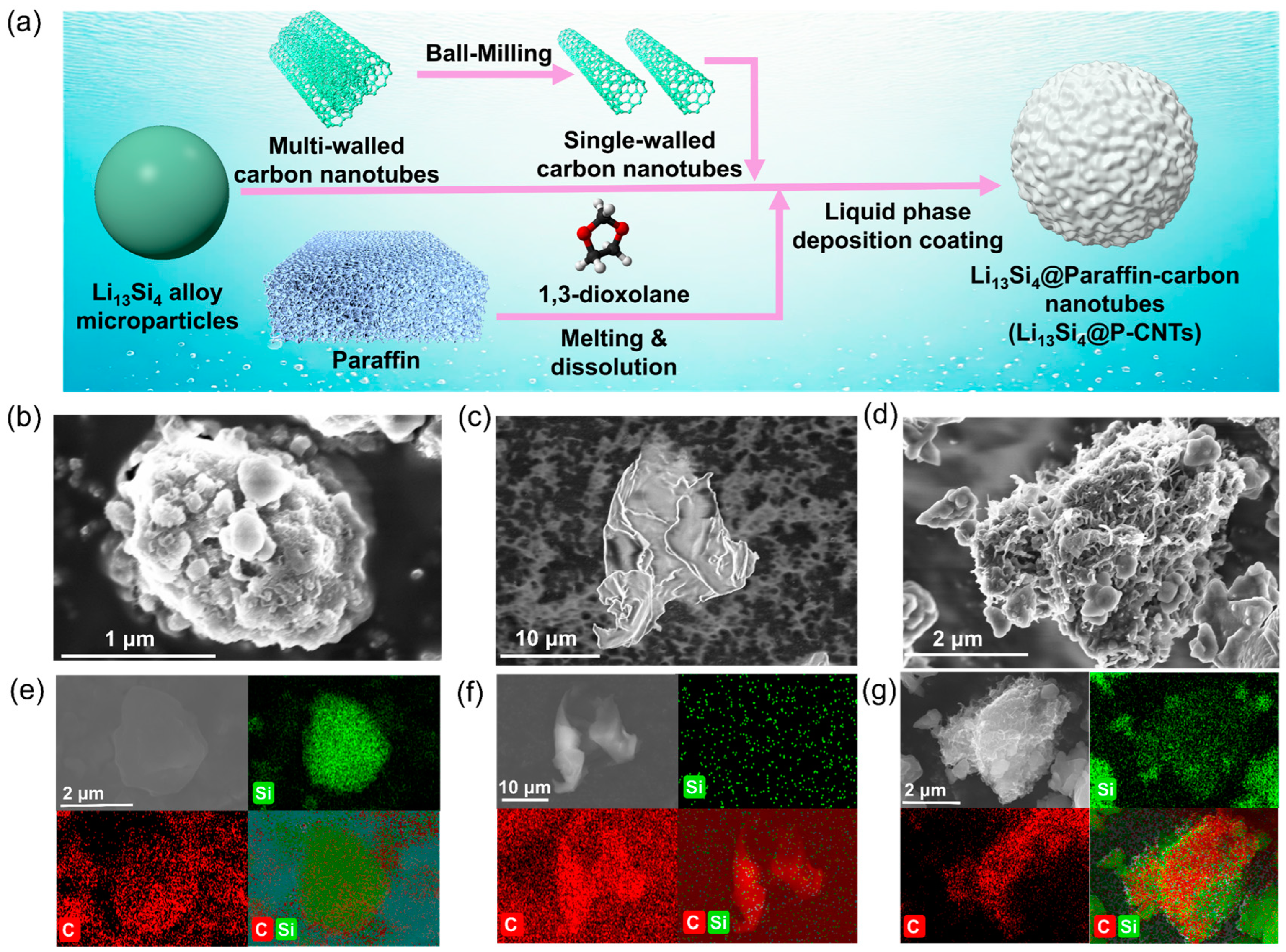
2.1. Synthesis and Morphology of Li13Si4@P-CNTs

Li–Si alloys are easily oxidized by moisture or oxygen in the air due to the enrichment of highly electropositive Li atoms, which makes them unable to compensate active lithium for anode materials [33,34]. Paraffin molecules are composed of saturated hydrocarbon chains. Their repeated nonpolar structural segments (–CH2–CH2–) and low surface energy result in the superior hydrophobicity of paraffin [35]. However, considering the poor Li+/e conductivity of paraffin, ball-milled CNTs were utilized to in situ crosslink on the surface of Li13Si4 microparticles in a melted paraffin/DOL solution. Furthermore, paraffin/CNTs composites enclosing Li13Si4 microparticles were obtained via liquid phase deposition, followed by cooling (Figure 1a). The morphological features and microstructures of the Li13Si4@P-CNTs and Li13Si4 precursors were investigated via scanning electron microscope (SEM). As shown in Figure 1b and Figure S1a, pristine Li13Si4 microparticles exhibit an elliptical morphology, with particle dimensions ranging from 2 to 10 μm. The blurred and rough surface of particles illustrates the poor conductivity of pristine Li13Si4. Paraffin presented a solid-state irregular block structure (10 μm) in observation via SEM (Figure 1c). It can be seen in Figure 1d and Figure S1b that plenty of wire-like CNTs wrap the Li13Si4 microparticles, exhibiting a uniform crosslinked network coating of the Li13Si4@P-CNTs. Bright wires following the shape of the CNT bundles indicate the enhancement of conductivity of Li13Si4@P-CNTs after coating. The distribution of elements of pristine Li13Si4 and Li13Si4@P-CNTs was characterized using SEM-energy dispersive spectrometer (EDS) element mapping. The EDS mappings reveal that the Li13Si4 precursors and paraffin show higher abundances of Si and C, respectively (Figure 1e,f and Figure S2). However, the appearance of C in pristine Li13Si4 may be ascribed to the Li2CO3 formed due to the oxidation of Li–Si alloys (LixSi → Li2CO3) during the SEM sample preparation process in air. The C element is evenly coated on the surface of Li13Si4@P-CNTs (Figure 1g), indicating the homogeneous 3D spatial combination of paraffin/CNTs composite in Li13Si4@P-CNTs. CNTs in the paraffin-CNT layer provide lithium ion transport paths and facilitate charge transfer. Under an applied external voltage, lithium ions migrate from the electrolyte to the inner electrode via CNTs and initiate the alloying reaction (Figure S3).

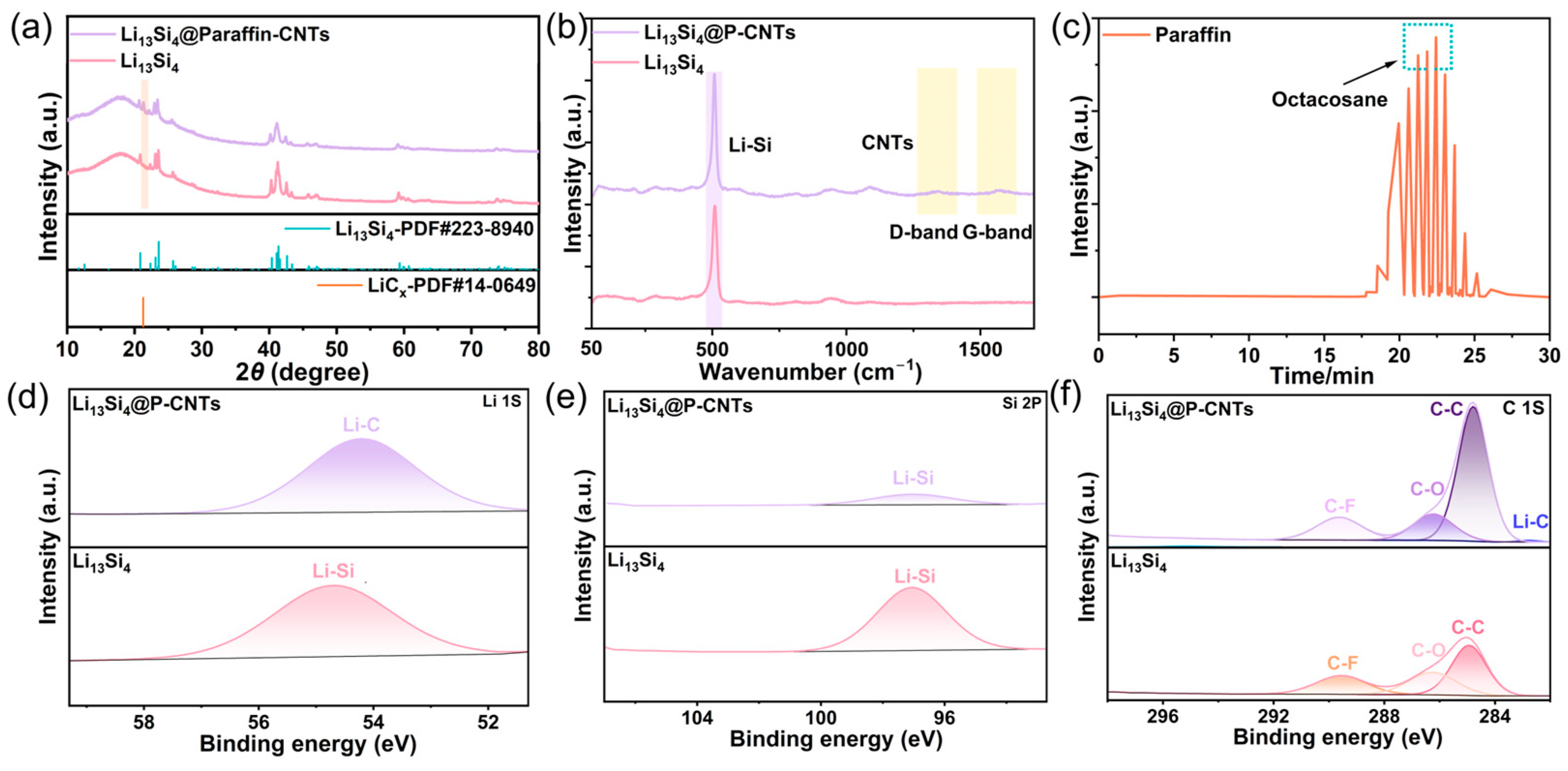
2.2. Crystal Properties and Surface Chemistry Characteristics of Li13Si4@P-CNTs

The characterization of crystal structure and chemical composition are used to further analyze the Li13Si4@P-CNTs properties. XRD profiles (Figure 2a) show diffraction peaks for pristine Li13Si4 at 20.8°, 23.1°, 23.6°, 40.4°, 41.1°, 41.3° and 41.6°, corresponding to the (130), (210), (111), (002), (061), (321), (340) and (222) lattice planes of Li13Si4 (PDF#223-8940). Meanwhile, the XRD pattern of Li13Si4@P-CNTs is basically consistent with the standard Li13Si4 phase, while the presence of the additional peak at 21.3° corresponds to the (021) lattice plane of LixC [36], indicating the lithiation of CNTs after paraffin/CNTs composite coating the Li13Si4 microparticles(C + Li13Si4 → LixC + LixSi). The Raman spectrum in Figure 2b presents three peaks: 508 cm−1 (Si-Si stretching vibrations), 1340 cm−1 (D band of CNTs) and 1596 cm−1 (G band of CNTs), respectively [37,38]. The characteristic peak at 508 cm−1 appears in both the Raman spectrum of the Li13Si4 precursor and Li13Si4@P-CNTs, reflecting the relaxation of Si-Si bonds in the c-Li13Si4 lattice. Meanwhile, peaks at 1340 cm−1 (D band) and 1596 cm−1 (G band) are only observed in the Raman spectrum of Li13Si4@P-CNTs, illustrating that the carbon nanotubes adhere to the surface of the Li13Si4 microparticles after liquid phase coating. The components of the paraffin mixture were further investigated using pyrolysis gas chromatography–mass spectrometry (Py-GCMS). The multi-component paraffin primarily consists of Octacosane and Tetratetracontane (Figure 2c), with straight–chain saturated alkane Octacosane being the most abundant component.
The surface chemistry characteristics of Li13Si4 and Li13Si4@P-CNTs were further investigated using X-ray photoelectron spectroscopy (XPS). As shown in Figure 2d, the intense peaks of Li13Si4 and Li13Si4@P-CNTs XPS Li 1s spectrum at a binding energy of 54.7 eV are ascribed to the Li-Si bond, while the intense peak at 54.2 eV can be observed on the spectrum of Li13Si4@P-CNTs, attributed to the LixC bond [39,40]. For the XPS Si 2p spectrum (Figure 2e), Li13Si4 exhibits an intense peak at 97 eV (Li-Si bond), which is significantly weaker in Li13Si4@P-CNTs [41]. The C 1s spectrum (Figure 2f) shows peaks at 282.8, 284.8, 286.5 and 289.5 eV, corresponding to Li-C (lithiation of CNTs), C-C/C-H (paraffin, CNTs and C in conductive adhesive base), C-O (O in conductive adhesive base) and C-F (F in conductive adhesive base), respectively [42,43]. Based on the results of XPS analysis, the Li-C (lithiated CNTs) bonds, increasing intensity of C-C/C-H (paraffin/CNTs composite coating) bonds and decreasing intensity of Li-Si bonds after coating further illustrates that a uniform paraffin/CNTs composite interface is successfully constructed on the surface of Li13Si4 microparticles based on liquid phase deposition. Figure S4 displays thermogravimetry (TG) curves of three samples (Li13Si4@P-CNTs, Li13Si4@CNTs and Li13Si4) heating from 30 to 350 °C. Only Li13Si4@P-CNTs shows a 12% mass loss between 160 and 300 °C, corresponding to the volatilization of the paraffin in the coating. On the other hand, a slight weight increment is observed in both Li13Si4@CNTs and Li13Si4, which is assigned to the reaction between LixSi and N2. These results illustrate that paraffin successfully coats the surface of Li13Si4 microparticles. Li13Si4@P-CNTs, Li13Si4@CNTs (obtained by ball milling Li13Si4 and CNTs composites), paraffin and CNTs are 0.1 mV, −0.1 mV, 0.7 mV and −0.3 mV, respectively (Figure S5). The Zeta potential shifts positively from −0.1 (Li13Si4@CNTs) to 0.1 mV due to the introduction of paraffin with positive surface charge (0.7 mV), illustrating that paraffin successfully coated on Li13Si4 microparticles.

2.3. Environmental Stability and Structural Evolution of Li13Si4@P-CNTs in Air

The coating membrane is predominantly composed of nonpolar straight-chain saturated alkane molecules (rich in repeating -CH2- units). This spatial arrangement of the chain decreases polar interactions with H2O molecules. The environmental stability and structural evolution of the Li13Si4@P-CNTs and pristine Li13Si4 pre-lithiation additives in air (45% RH) for 120 min are further systematically investigated through in situ XRD characterization. In the in situ XRD spectra of Li13Si4@P-CNTs pre-lithiation additives with air exposure (Figure 3a), the characteristic peaks are at 20.8°, 23.1°, 23.6°, 40.4°, 41.1°, 41.3°, 41.6° and 21.3°, corresponding to the (130), (210), (111), (002), (061), (321), (340) and (222) lattice planes of Li13Si4 and the (021) lattice plane of LixC. The intensities and positions of all the above peaks remain constant before and after the long-term air exposure process, illustrating that Li13Si4@P-CNTs exhibit enhanced environmental stability in humid air (45% RH). On the other hand, as shown in Figure 3b, the attenuation of Li13Si4/LixC characteristic peaks and enhancement of the LiOH characteristic peak represent the crystalline phase transition from Li13Si4 to LiOH during the air exposure of pristine Li13Si4, suggesting the high air sensitivity of pristine Li13Si4 without hydrophobic paraffin/CNTs composite coating membrane.

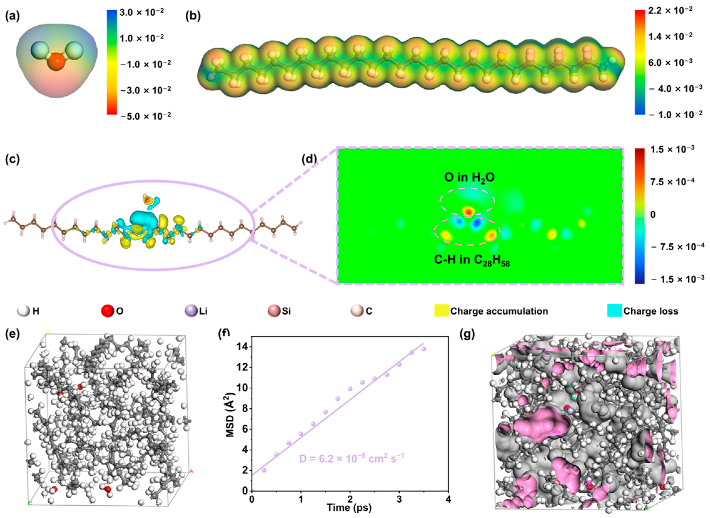
2.4. Theoretical Study on the Hydrophobic Mechanism of Paraffin-Dominant Coating Membrane

To further understand the hydrophobicity and environmental stability exhibited by the Li13Si4@P-CNTs after paraffin coating, density functional theory (DFT) and molecular dynamics simulations were performed and analyzed (paraffin was replaced by its main component, Octacosane, C28H58). As shown in the electrostatic potential mapping image of the water molecule (Figure 4a and Figure S6a), the local electrostatic potential of H2O varies from −0.479 eV to 0.240 eV. The H atoms and O atoms separately exhibit strong positive potential and negative potential, indicating that the H2O molecule exhibits strong polarity. However, the low difference in surface electrostatic potential (−0.084 eV~0.042 eV) and weak polarity can be observed in paraffin (C28H58) in Figure 4b and Figure S6b. Furthermore, a charge density difference was measured to qualitatively analyze the charge density distribution at the hetero-interface of H2O-C28H58. Figure 4c illustrates the charge depletion in cyan and charge accumulation in yellow. Meanwhile, the charge density distribution (Figure 4c,d) further illustrates that the hetero-interface zones exhibit a small concentration of both positive and negative charge densities. The positive charges exhibit a low tendency to accumulate on H atoms of C28H58 and the negative ones are slightly probable to gather on the O atom of H2O. This illustrates that paraffin coating exhibits weak dipole–dipole interaction with negatively charged O atoms of H2O (van der Waals force). Therefore, the paraffin-dominant hydrophobic coating membrane of Li13Si4@P-CNTs improves their environmental stability in humid air.
To theoretically understand the water molecule transport behavior through the paraffin-dominant membrane around Li13Si4 microparticles, molecular dynamics simulations were performed. The canonical ensemble (NVT) and the unrestrained micro-canonical ensemble (NVE) were used in the simulation. The model for the H2O-paraffin system, containing eight C28H58 and five H2O molecules, is shown in Figure 4e. As shown in Figure 4f, the diffusion coefficient of water in the H2O-paraffin system is 6.2 × 10⁻⁵ cm2·s−1, much lower than that in the air (0.26 cm2 s−1) [44]. Thus, it can be concluded that the external paraffin-dominant membrane of Li13Si4@P-CNTs inhibits the diffusion of water molecules. FFV is a characteristic used to quantify molecular transport performance in a transport medium [45]. The pink surface in Figure 4g illustrates the free volume of molecules in the H2O-paraffin system. The FFV is 20.3%, reflecting the low water permeability of the dense and uniform paraffin-dominant membrane on Li13Si4. These results indicate that the paraffin-dominant membrane, exhibiting weak interaction with water molecules, imparts Li13Si4@P-CNTs with superior hydrophobicity and enhances its environmental stability.

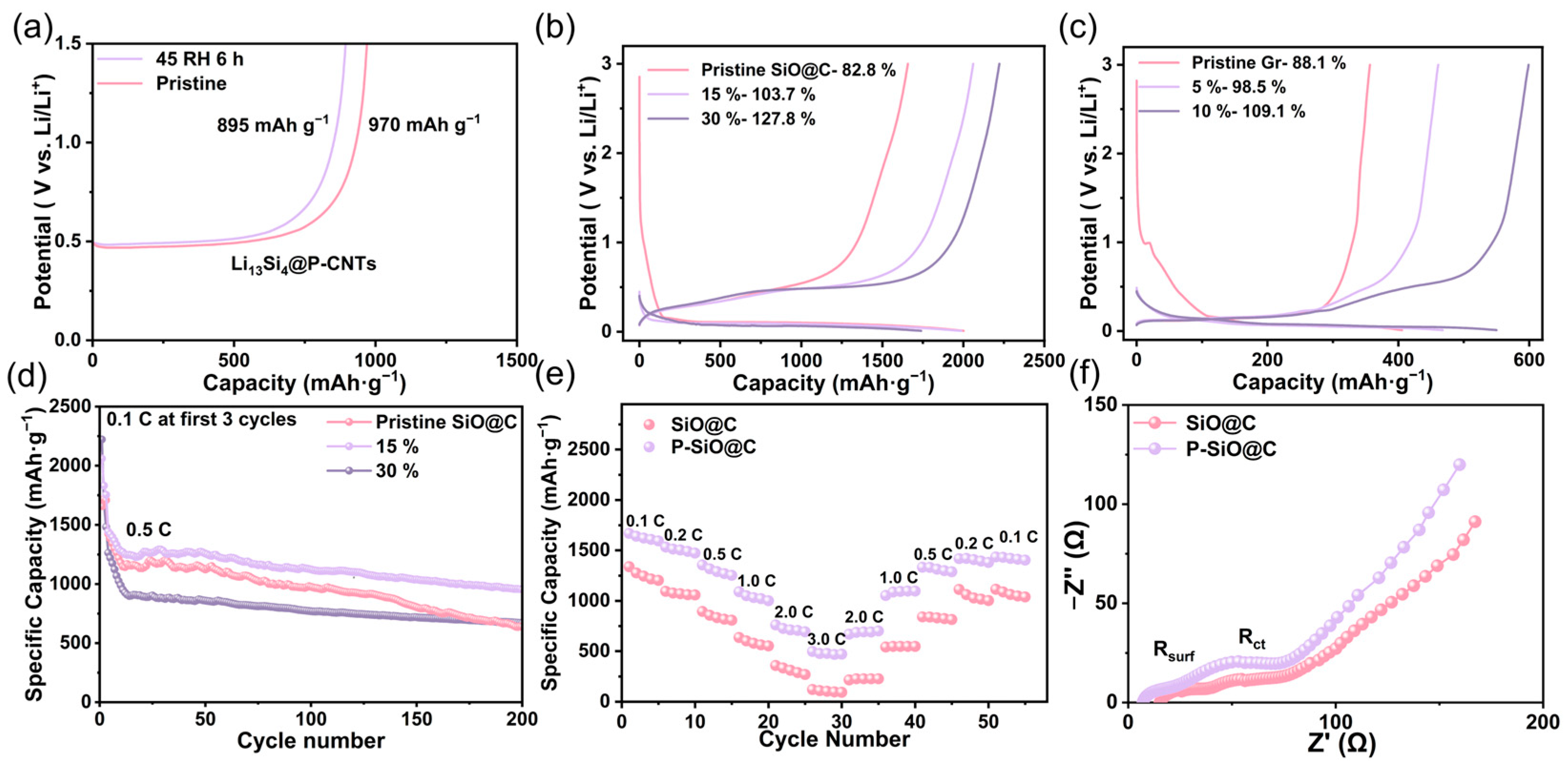
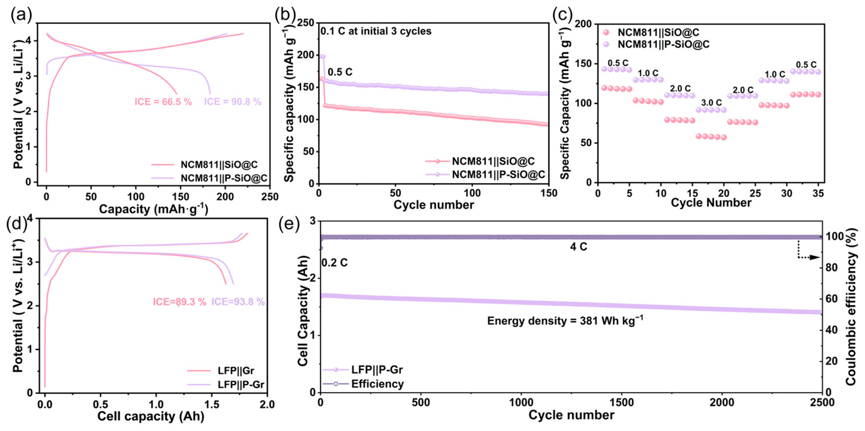
2.5. Electrochemical Performance of Li13Si4@PFPE/LiF Pre-Lithiated Anode

To verify the intrinsic electrochemical performance of Li13Si4@P-CNTs and its beneficial effect on improving the performance of half cells, a galvanostatic charge–discharge test and rate performance analysis are investigated in the section below. As shown in Figure 5a, the pre-lithiation capacities of Li13Si4@P-CNTs anodes before and after exposure to 45% RH air for 6 h are 970 and 895 mAh g−1 (based on the total mass of Li13Si4, paraffin and CNT), respectively.
Furthermore, the pre-lithiation capacity retention is 92.2%, indicating that the Li13Si4@P-CNTs, with a hydrophobic paraffin-dominant coating, retains a superior pre-lithiation capacity after exposure to air. The protective effect of the paraffin/CNTs composite membrane on Li13Si4@P-CNTs is further validated by their electrochemical performance after long-term air exposure and polar solvent immersion tests. Li13Si4@P-CNTs still achieves a specific capacity of 413 mAh g−1 after being exposed to 45% RH air for 360 h (Figure S7a) and shows a capacity of 401 mAh g−1 after immersion in THF for 720 h (Figure S7b), illustrating that Li13Si4@P-CNTs retains a chemical structure and electrochemical activity after exposure to air or polar solvent. Half cells with different addition amounts of Li13Si4@P-CNTs were used to further investigate the impact of the pre-lithiation degree on the ICEs and cyclability of SiO@C or Gr anodes. As shown in Figure 5b, the introduction of 15% and 30% Li13Si4@P-CNTs to SiO@C anodes results in a significant increase in ICEs, from 82.8% for the pristine anode to 103.7% and 127.8%, respectively. A similar trend is observed for pre-lithiated Gr (P-Gr) anodes in Figure 5c, where the ICE increases from 88.1% (pristine) to 98.5% (5% addition) and 109.1% (10% addition). These results demonstrate that the Li13Si4@P-CNTs effectively facilitates the pre-lithiation of both Si-based and graphite anodes, with the pre-lithiation degree precisely regulated by the amount of Li13Si4@P-CNTs. Furthermore, for the pristine SiO@C anode and P-SiO@C anodes with various amounts of 15% and 30% Li13Si4@P-CNTs, the capacity retentions after 200 cycles are 43.5%, 66.8% and 53.7%, respectively (Figure 5d). Specifically, the P-SiO@C anode with a moderate pre-lithiation level (15%) exhibits the best cycling stability and is designated as P-SiO@C for subsequent research.
The rate performance of the pristine SiO@C and P-SiO@C anodes was further evaluated. As shown in Figure 5e, the P-SiO@C anode exhibits a superior rate capability with discharge capacities of 1009, 686 and 474.5 mAh g−1 at 1 C, 2 C and 3 C, respectively. On the other hand, the SiO@C anode retains only 559, 273 and 99 mAh g−1 discharge capacities at corresponding rates. EIS analysis was performed to investigate the effect of Pre-SEI after pre-lithiation on the impedance of the SiO@C anodes. As shown in Figure 5f, Nyquist plots usually show up as sloping straight lines in the low-frequency region and half circles in the high-frequency range. The kinetic parameters of both anodes were fitted based on the equivalent circuits in Figure S8. Rs represents the bulk resistance of the battery components, while Rct corresponds to the charge-transfer resistance and CPE denotes the double-layer capacitance [46]. Charge-transfer resistance is associated with the mid- to low-frequency range and the high-frequency region represents the impedance of Li+ passing through SEI [47]. The cycled P-SiO@C exhibits an Rct of 98.2 and Rsurf of 23.7 Ω, which are lower than that of SiO@C (Rct = 105.2 Ω and Rsurf = 30.5 Ω) after 200 cycles. Meanwhile, in comparison to pristine SiO@C, a steeper slope tail of the EIS profile of P-SiO@C indicates improved Li-ion diffusion after pre-lithiation. The results further illustrate that the kinetics of the cycled SiO@C enhance with the pre-lithiation treatment.

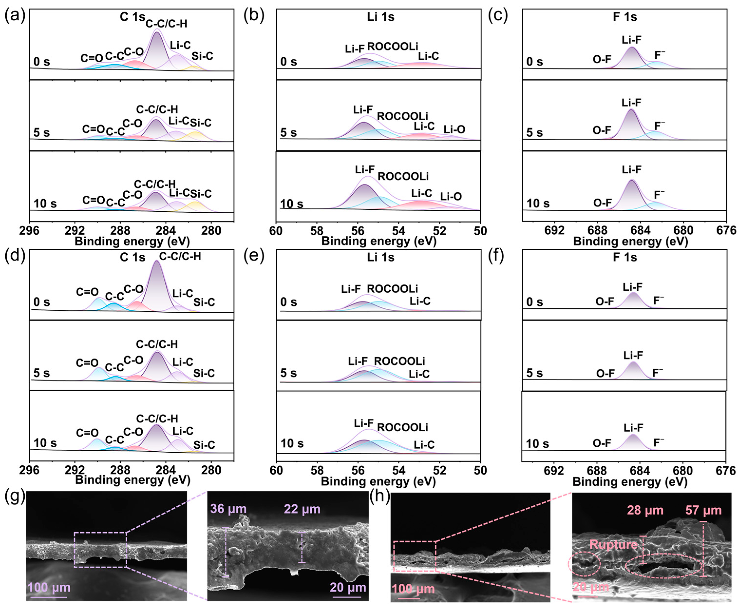
2.6. SEI Regulation of Pre-Lithiation SiO@C via Li13Si4@P-CNTs

The SEI formation evolution and volume expansion of pre-lithiated anodes after cycling are systematically investigated in this section. To further analyze the chemical components of the anode surface before and after pre-lithiation of SiO@C at different thicknesses, the electrode surface is deeply etched at 5-second intervals with etching times of 0, 5 and 10 s. As shown in the XPS C 1s spectrum of SiO@C/P-SiO@C anodes (Figure 6a,d), the peaks with binding energies of 281.5 eV, 283.2 eV, 284.8 eV, 286.5 eV, 289 eV and 290 eV correspond to characteristic peaks associated with bonds of Si-C, Li-C, C-C/C-H, C-O, C-C and C=O. As shown in Figure 6b,e, the deconvolution of XPS Li 1s peaks can be divided into Li-O (51.5 eV), Li-C (52.8 eV), ROCOOLi (55 eV) and LiF (55.7 eV) [48,49,50,51]. The intense peaks near 682.5 eV, 684.7 eV and 687 eV originate from F, LiF and LiPOFz, respectively [52,53]. These results indicate that surface components of SiO@C and P-SiO@C are composed of LixC, SiC, free fluoride ion, organic lithium salts (ROCOOLi) and inorganic lithium salts (LiF, Li2O and LiPOFz).
Furthermore, the variation in SEI components at different etching levels is clarified through the XPS data of SiO@C and P-SiO@C. As the etch deepens, there are obvious decreases in the proportion and peak intensity of C-C/C-H/C-O organics (C 1s in Figure 6a,d), while the intensity of diffraction peaks of inorganic Li salts (LiF and Li2O) increases in the P-SiO@C anode (Li 1s and F 1s in Figure 6b,c,e,f). In contrast to P-SiO@C, with the increased sputtering time, Figure 6d exhibits a decrease in organics (ROCOOLi, C-C, C-H and C-O) in SEI of SiO@C, while Figure 6e,f show no consistent trend of lithium salts (LiF and Li2O). Meanwhile, P-SiO@C has significantly fewer organic SEI components and more inorganic Li salts (e.g., LiF and Li2O) on the surface of the electrode in comparison to pristine SiO@C, illustrating that pre-lithiation may regulate components of SEI and enhance its Li+ transport kinetics. To evaluate the structural variation in the SiO@C/P-SiO@C anode during galvanostatic cycling, two anodes with equal thickness were fully lithiated in half cells and then observed via SEM. The cross-sectional SEM figures of fully lithiated P-SiO@C and SiO@C electrodes after cycling are presented in Figure 6g and Figure 6h, respectively. The cross-sectional image of the cycled P-SiO@C exhibits a basically even, stable and intact interface with thickness from 22 μm to 36 μm, whereas the cross-section of the cycled SiO@C shows an inhomogeneous electrode (28 μm to 57 μm) with many internal cracks/ruptures and active materials separation, attributed to stress failures caused by the repeated significant volume change in SiO@C during cycling. Therefore, the absence of cracks and decreasing thickness of the cross-section of cycled anodes illustrate that pre-lithiation of SiO@C via Li13Si4@P-CNTs alleviates the volume variation in SiO@C and enhances the mechanical stability of anodes.

2.7. Full Cell Model Evaluation Based on Li13Si4@PFPE/LiF Pre-Lithiation Strategy

The commercial pre-lithiation potential of Li13Si4@P-CNTs was further investigated in full-cell and pouch-cell configurations with the pristine/pre-lithiated Gr or SiO@C anodes. The ICE increases from 66.5% to 90.8% in NCM811||SiO@C full cells before and after pre-lithiation (Figure 7a). This verifies that the Li13Si4@P-CNTs powder pre-lithiation compensates for the active Li loss induced by SEI formation during the initial cycle. The cyclability of pristine/pre-lithiated full cells was further studied, as shown in Figure 7b. The specific capacity of NCM811||SiO@C battery rapidly declines from 121.2 to 90.8 mAh g −1 after 150 cycles with a low capacity retention (74.2%). On the other hand, the pre-lithiated cell exhibits a high discharge capacity of 149.1 mAh g−1 and capacity retention of 86.8% during 150 cycles. As shown in Figure 7c, the NCM811||P-SiO@C exhibits an average discharge capacity of 141.19, 129.66, 109.9 and 91.5 mAh g−1, with various rates at 0.5, 1, 2 and 3 C, respectively. Meanwhile, the NCM811||P-SiO@C can still return to a high discharge capacity of 139.8 mAh g−1 after 35 cycles. In contrast, the pristine SiO@C shows a low rate performance, only maintaining discharge capacities of 117.8, 102.6, 78.9 and 56.5 mAh g−1 at 0.5 C, 1 C, 2 C and 3 C, respectively.
To further assess the practicality of Li13Si4@P-CNTs in anode pre-lithiation, the pouch cell test was performed. The assembled LFP||P-Gr pouch cell achieves a superior ICE (93.8%), favorable capacity retention (83.2% at 2500 cycles) and ultrahigh energy density (381 Wh kg−1) in Figure 7d,e (the energy density was calculated based on the mass of the cathode). Furthermore, in SiO@C/Gr composite systems, the LFP||P-SiO@C/Gr pouch full cell delivers a superior energy density of 408 Wh kg−1 after 2000 cycles (Figure S9). These results demonstrate the outstanding potential of Li13Si4@P-CNTs additives for practical application in anode pre-lithiation of high-energy-density LIBs.

3. Materials and Methods

3.1. Preparation and Synthesis of Li13Si4 and Li13Si4@P-CNTs

The Li13Si4 microparticles (50 mesh) were purchased from Shandong Chongshan Optoelectronic Materials Co., Ltd. (Zibo, China). To synthesize the Li13Si4 precursors, 1 g of pristine Li13Si4 particles and 3 g of Zirconia balls were placed inside a stainless-steel milling jar (45 mL). Ball-milling was performed in a planetary mill (P7, Fritsch, Idar-Oberstein, Germany) for 4 h at 400 rpm. Then, 1 g multi-walled carbon nanotubes (Canrd, Dongguan, China) were ball-milled with Zirconia balls at 100 rpm. The paraffin (Macklin, Shanghai, China), 1,3-Dioxolane (Dol, Aladdin, Shanghai, China), ball-milled Li13Si4 microparticles (2–10 μm) and CNTs were utilized to prepare the Li13Si4@P-CNTs. A total of 10 mL of Dol was used to dissolve 200 mg melted paraffin at 400 rpm stirring rate and 65 °C heating temperature. Then, ball-milled carbon nanotubes (5 mg) and Li13Si4 microparticles (400 mg) were mechanically ground and subsequently added to paraffin-Dol solution. The solution was stirred for 2 h and further cooled to room temperature for 1 h. The well-mixed solution was vacuum-filtered, followed by vacuum drying to obtain the uniformly coated Li13Si4@P-CNTs.

3.2. Materials Characterization

SEM (Zeiss, Zigma, Oberkochen, Germany) was utilized to study the morphology and microstructure of the pristine Li13Si4 and Li13Si4@P-CNTs. The crystal structures of the pristine Li13Si4 and Li13Si4@P-CNTs were investigated through a powder XRD (Rigaku SmartLab, Tokyo, Japan) and XPS was performed using Thermo ESCALAB Xi+ XPS Microprobe (Thermo Fisher Scientific ESCALAB Xi+, Waltham, MA, USA). Based on a laser with a wavelength of 532 nm, Horiba Evolution was used to generate Raman spectra (Horiba LABHRev-UV, Kyoto, Japan). Pyrolysis-GC/MS was used to confirm the composition distribution of the long-chain alkanes in paraffin (Thermo Scientific TRACE 1310, Waltham, MA, USA, Thermo Scientific ISQ LT, Waltham, MA, USA).

3.3. Electrochemical Measurement

Using a weight ratio of 6.5:2:1.5, Li13Si4/Li13Si4@P-CNTs, Super P and PVDF were mixed with Dol solvent and stirred to obtain a homogeneous slurry. To prepare the Li13Si4/Li13Si4@P-CNTs electrodes, the slurry was casted on copper foil, dried and cut into disks of 12 mm in diameter. The mass loadings of Li13Si4/Li13Si4@P-CNTs electrodes were generally between 1.2 and 1.8 mg cm−2. Celgard 2340 Polypropylene (PP) and lithium metal were employed as the separator and anode, respectively. The electrolyte was 1.0 M LiPF6 in EC and DEC (V/V = 1:1) with a 5 wt% FEC additive. The assembled cells were measured using NEWARE battery test system. The cells for the EIS experiment were assembled identically and measured using a CHI 760 electrochemical workstation, with a frequency range spanning from 0.01 to 105 Hz. The SiO@C electrode was prepared by mixing SiO@C (M33-3, Macau Aolixin Technology Co., Ltd., Macau), Super P and polyacrylic acid (PAA) in 95% ethanol with a weight ratio of 70:20:10, followed by casting and vacuum dried. And P-SiO@C was fabricated by casting the Dol dispersion of Li13Si4@P-CNTs, Super P and PVDF (mass ratio 45:5:10) on the low-loading SiO@C electrode via the pre-lithiation layer strategy. The Gr and P-Gr electrodes were completed using a similar method for the SiO@C and P-SiO@C electrodes, respectively.
The full cells were assembled with the NCM811 cathodes and the SiO@C/P-SiO@C anodes. The pouch cells were assembled with the LFP cathodes and the Gr/P-Gr/SiO@C-Gr/P-SiO@C-Gr anodes.

3.4. DFT and Molecular Dynamics Simulation

The first principles calculations from DFT were carried out using the Vienna Ab Initio simulation package (VASP) and the Dmol3 module of Materials Studio. To further investigate their molecular electrostatic potential and interaction, the geometry optimization and electronic energy state calculation were conducted under the generalized gradient approximation (GGA) with Perdew−Burke–Ernzerhof (PBE). The convergence tolerance of energy and force was set to 1 × 10⁻⁵ eV/atom and 2 × 10⁻² eV/Å, respectively. The differential charge density distribution was post-processed using Vesta software (ver. 3.5.8). Molecular dynamics (MD) simulations were performed to analyze the difference in diffusion kinetics of H2O in the paraffin system through the Forcite module in Materials Studio. The H2O-paraffin system was constructed using the Amorphous Cell module. The COMPASS force field was used in all the calculations. Specifically, the system was subject to a 0.5 ps canonical ensemble (NVT). After the equilibration stage, the 4.5 ps unrestrained micro-canonical ensemble (NVE) simulation was performed at 298 K.
The NVE production step was sampled for analysis of the diffusion coefficient (D) and the FFV, given by Equations (1) and (2), respectively [54,55]:
D = 1 6 N a lim t d d t i N a < γ i t γ i 0 2 >
η = V f r e e V o c c u p y + V f r e e × 100 %
where Na represents the number of atoms to be tested and ri(t) and ri(0) are the coordinates of the ith particle at time t and time 0, respectively. η represents the free volume fraction, Vfree represents the volume available for detection and Voccupy is the remaining volume.

4. Conclusions

In conclusion, an effective anode pre-lithiation strategy Via protective coating additives is proposed to resolve the issue of high air sensitivity of Li–Si alloy pre-lithiation additives. We designed a composite membrane on the basis of hydrophobic paraffin and conductive CNTs to coat the Li13Si4 microparticles via liquid phase deposition, which integrates superior environmental stability and high Li+/e transport kinetics. The Li13Si4@P-CNTs shows a superior pre-lithiation capacity of 895 mAh g−1 and capacity retention of 92.2% after exposure to 45% RH air for 6 h, which is attributed to the hydrophobic paraffin protection membrane based on the weak dipole–dipole interaction between C28H58 and H2O. Furthermore, the Li13Si4@P-CNTs significantly enhances the charge transfer dynamics and SEI Li+ transport kinetics of the P-SiO@C electrode, as illustrated by EIS and XPS depth etching results. Using Li13Si4@P-CNTs pre-lithiation additives, the NCM811||P-SiO@C full cell delivers an enhanced cyclability (149.1 mAh g−1 at 150 cycles) and high rate of performance (91.5 mAh g−1 at 3C). Furthermore, the LFP||P-Gr pouch cell achieves a maximum energy density of 381 Wh kg−1 after 2500 cycles, demonstrating its potential for practical applications. This environmentally stable and scalable Li–Si alloy additive enclosed by a protective membrane is an important guideline for the industrial pre-lithiation of Si-based materials for LIBs.

Supplementary Materials

The following supporting information can be downloaded at https://www.mdpi.com/article/10.3390/inorganics13040115/s1. Figure S1. (a, b) SEM images of (a) pristine Li13Si4 and (b) Li13Si4@P–CNTs. Figure S2. (a) SEM and (b, c) EDS elemental mappings of pristine Li13Si4. Figure S3. Schematic illustration of lithium-ion transport mechanisms in paraffin–CNT layer. Figure S4. TGA curves of Li13Si4@P–CNTs, Li13Si4@CNTs and Li13Si4. Figure S5. Zeta potential of (a) Li13Si4@P–CNTs and paraffin; (b) Li13Si4@CNTs and CNTs. Figure S6. (a, b) The charge distribution of (a) water molecule and (b) paraffin (C28H58). Figure S7. (a) The pre-lithiation capacity of Li13Si4@P–CNTs before and after exposure in 45% RH air for 360 h. (b) The pre-lithiation capacity of Li13Si4@P–CNTs before and after exposure in Tetrahydrofuran solvent for 720 h. Figure S8. EIS Equivalent circuits of SiO@C electrodes and P–SiO@C electrodes pre-lithiated by Li13Si4@P–CNTs pre-lithiation additives after 200 cycles. Figure S9. Capacity and Coulombic efficiency versus cycle number of LiFePO4(LFP) ||P–SiO@C/Gr pouch full cells.

Author Contributions

Conceptualization, H.S., Y.L. and W.J.; methodology, Y.L., W.J. and J.G.; software, W.J. and J.G.; validation, Y.L., W.J. and K.Y.; formal analysis, Y.L., J.W., Y.H. and Y.Q.; investigation, J.G., Y.S. and C.Z.; resources, Y.L., W.J., L.L., Y.Z., R.C. and P.J.; data curation, W.J., J.G., P.J., Z.Z. and B.Z.; writing—original draft preparation, Y.L. and W.J.; writing—review and editing, W.J. and J.G.; visualization, Y.L. and J.G.; supervision, H.S., Y.L., J.W. and Y.Q.; project administration, Y.L.; revision, Y.L., W.J., C.Z., P.J., Z.Z., Y.Z., K.Y., J.W. and Y.Q.; funding acquisition, H.S. All authors have read and agreed to the published version of the manuscript.

Funding

This work is funded by the Shenzhen-Hong Kong-Macau Science and Technology Plan Project (Category C) (grant No. SGDX20220530111004028), the Macau Science and Technology Development Fund (FDCT) for funding FDCT No. 0013/2024/RIB1, FDCT-MOST joint project No. 0026/2022/AMJ and No. 006/2022/ALC of the Macao Centre for Research and Development in Advanced Materials (2022–2024), the Multi-Year Research Grant (MYRG) from the University of Macau (project No. MYRG-GRG2023-00140-IAPME-UMDF and No. MYRG-GRG2024-00206-IAPME), the Natural Science Foundation of Guangdong Province (grant No. 2023A1515010765) and the Science and Technology Program of Guangdong Province of China (grant No. 2023A0505030001).

Institutional Review Board Statement

Not applicable.

Informed Consent Statement

Not applicable.

Data Availability Statement

The raw data supporting the conclusions of this article will be made available by the authors upon request.

Conflicts of Interest

Author Yunxian Qian was employed by the company Shenzhen CAPCHEM Technology Co., Ltd. The remaining authors declare that the research was conducted in the absence of any commercial or financial relationships that could be construed as a potential conflict of interest.

References

  1. Xu, C.J.; Behrens, P.; Gasper, P.; Smith, K.; Hu, M.M.; Tukker, A.; Steubing, B. Electric vehicle batteries alone could satisfy short-term grid storage demand by as early as 2030. Nat. Commun. 2023, 14, 11. [Google Scholar] [CrossRef] [PubMed]
  2. Tan, D.H.S.; Banerjee, A.; Chen, Z.; Meng, Y.S. From nanoscale interface characterization to sustainable energy storage using all-solid-state batteries. Nat. Nanotechnol. 2020, 15, 170–180. [Google Scholar]
  3. Cano, Z.P.; Banham, D.; Ye, S.Y.; Hintennach, A.; Lu, J.; Fowler, M.; Chen, Z.W. Batteries and fuel cells for emerging electric vehicle markets. Nat. Energy 2018, 3, 279–289. [Google Scholar] [CrossRef]
  4. Mauger, A.; Julien, C.M. Remedies to avoid failure mechanisms of lithium-metal anode in Li-ion batteries. Inorganics 2022, 10, 5. [Google Scholar]
  5. Roy, J.J.; Phuong, D.; Verma, V.; Chaudhary, R.; Carboni, M.; Meyer, D.; Cao, B.; Srinivasan, M. Direct recycling of Li-ion batteries from cell to pack level: Challenges and prospects on technology, scalability, sustainability and economics. Carbon Energy 2024, 6, 39. [Google Scholar] [CrossRef]
  6. Klett, M.; Gilbert, J.A.; Pupek, K.Z.; Trask, S.E.; Abraham, D.P. Layered oxide, graphite and silicon-graphite electrodes for lithium-ion cells: Effect of electrolyte composition and cycling windows. J. Electrochem. Soc. 2016, 164, A6095. [Google Scholar]
  7. Qi, Y.; Harris, S.J. In situ observation of strains during lithiation of a graphite electrode. J. Electrochem. Soc. 2010, 157, A741. [Google Scholar] [CrossRef]
  8. Yin, Y.; Zheng, T.; Chen, J.; Peng, Y.; Fang, Z.; Mo, Y.; Wang, C.; Wang, Y.; Xia, Y.; Dong, X. Uncovering the function of a five-membered heterocyclic solvent-based electrolyte for graphite anode at subzero temperature. Adv. Funct. Mater. 2023, 33, 2215151. [Google Scholar] [CrossRef]
  9. Chae, C.; Noh, H.J.; Lee, J.K.; Scrosati, B.; Sun, Y.K. A high-energy Li-ion battery using a silicon-based anode and a nano-structured layered composite cathode. Adv. Funct. Mater. 2014, 24, 3036–3042. [Google Scholar] [CrossRef]
  10. Yeom, S.J.; Lee, C.; Kang, S.; Wi, T.-U.; Lee, C.; Chae, S.; Cho, J.; Shin, D.O.; Ryu, J.; Lee, H.-W. Native void space for maximum volumetric capacity in silicon-based anodes. Nano Lett. 2019, 19, 8793–8800. [Google Scholar]
  11. Yang, Y.; Ni, C.; Gao, M.; Wang, J.; Liu, Y.; Pan, H. Dispersion-strengthened microparticle silicon composite with high anti-pulverization capability for Li-ion batteries. Energy Storage Mater. 2018, 14, 279–288. [Google Scholar] [CrossRef]
  12. Yang, Y.; Qu, X.; Zhang, L.; Gao, M.; Liu, Y.; Pan, H. Reaction-ball-milling-driven surface coating strategy to suppress pulverization of microparticle Si anodes. ACS Appl. Mater. Interfaces 2018, 10, 20591–20598. [Google Scholar] [CrossRef]
  13. Qin, M.; Liu, M.; Zeng, Z.; Wu, Q.; Wu, Y.; Zhang, H.; Lei, S.; Cheng, S.; Xie, J. Rejuvenating propylene carbonate-based electrolyte through nonsolvating interactions for wide-temperature Li-ions batteries. Adv. Energy Mater. 2022, 12, 2201801. [Google Scholar] [CrossRef]
  14. Wang, Z.; Fu, Y.; Zhang, Z.; Yuan, S.; Amine, K.; Battaglia, V.; Liu, G. Application of stabilized lithium metal powder (SLMP) in graphite anode–a high efficient prelithiation method for lithium-ion batteries. J. Power Sources 2014, 260, 57–61. [Google Scholar] [CrossRef]
  15. Shen, Y.; Shen, X.; Yang, M.; Qian, J.; Cao, Y.; Yang, H.; Luo, Y.; Ai, X. Achieving desirable initial Coulombic efficiencies and full capacity utilization of Li-ion batteries by chemical prelithiation of graphite anode. Adv. Funct. Mater. 2021, 31, 2101181. [Google Scholar] [CrossRef]
  16. Li, B.; Xiao, Z.; Zai, J.; Chen, M.; Wang, H.; Liu, X.; Li, G.; Qian, X. A candidate strategy to achieve high initial Coulombic efficiency and long cycle life of Si anode materials: Exterior carbon coating on porous Si microparticles. Mater. Today Energy 2017, 5, 299–304. [Google Scholar] [CrossRef]
  17. Wang, J.; Liao, L.; Lee, H.R.; Shi, F.; Huang, W.; Zhao, J.; Pei, A.; Tang, J.; Zheng, X.; Chen, W. Surface-engineered mesoporous silicon microparticles as high-coulombic-efficiency anodes for lithium-ion batteries. Nano Energy 2019, 61, 404–410. [Google Scholar] [CrossRef]
  18. Ma, W.; Wu, H.; Long, T.; Cai, Y.; Yu, Z.; Liu, C.; Fang, G.; Zhang, Q.; Jia, X. Bamboo inspired silicon anodes with ultrahigh initial Coulombic efficiency and high capacity for the Li-ion batteries. Small 2024, 20, 2308109. [Google Scholar] [CrossRef]
  19. Kim, M.K.; Jang, B.Y.; Lee, J.S.; Kim, J.S.; Nahm, S. Microstructures and electrochemical performances of nano-sized SiOx (1.18 ≤ x ≤ 1.83) as an anode material for a lithium (Li)-ion battery. J. Power Sources 2013, 244, 115–121. [Google Scholar] [CrossRef]
  20. Zhang, J.; Zhang, C.; Liu, Z.; Zheng, J.; Zuo, Y.; Xue, C.; Li, C.; Cheng, B. High-performance ball-milled SiOx anodes for lithium ion batteries. J. Power Sources 2017, 339, 86–92. [Google Scholar] [CrossRef]
  21. Liu, Z.; Yu, Q.; Zhao, Y.; He, R.; Xu, M.; Feng, S.; Li, S.; Zhou, L.; Mai, L. Silicon oxides: A promising family of anode materials for lithium-ion batteries. Chem. Soc. Rev. 2019, 48, 285–309. [Google Scholar] [CrossRef]
  22. Zhang, Y.; Guo, G.; Chen, C.; Jiao, Y.; Li, T.; Chen, X.; Yang, Y.; Yang, D.; Dong, A. An affordable manufacturing method to boost the initial Coulombic efficiency of disproportionated SiO lithium-ion battery anodes. J. Power Sources 2019, 426, 116–123. [Google Scholar]
  23. Li, Y.; Zheng, X.; Cao, Z.; Wang, Y.; Wang, Y.; Lv, L.; Huang, W.; Huang, Y.; Zheng, H. Unveiling the mechanisms into Li-trapping induced (Ir) reversible capacity loss for silicon anode. Energy Storage Mater. 2023, 55, 660–668. [Google Scholar]
  24. Sun, L.; Liu, Y.; Wu, J.; Shao, R.; Jiang, R.; Tie, Z.; Jin, Z. A review on recent advances for boosting initial coulombic efficiency of silicon anodic lithium ion batteries. Small 2022, 18, 2102894. [Google Scholar]
  25. Zhan, R.; Wang, X.; Chen, Z.; Seh, Z.W.; Wang, L.; Sun, Y. Promises and challenges of the practical implementation of prelithiation in lithium-ion batteries. Adv. Energy Mater. 2021, 11, 2101565. [Google Scholar]
  26. Wang, R.; Li, H.; Wu, Y.; Li, H.; Zhong, B.; Sun, Y.; Wu, Z.; Guo, X. How to promote the industrial application of SiOx anode prelithiation: Capability, accuracy, stability, uniformity, cost and safety. Adv. Energy Mater. 2022, 12, 2202342. [Google Scholar] [CrossRef]
  27. Yang, Q.; Hu, J.; Meng, J.; Li, C. C–F-rich oil drop as a non-expendable fluid interface modifier with low surface energy to stabilize a Li metal anode. Energy Environ. Sci. 2021, 14, 3621–3631. [Google Scholar] [CrossRef]
  28. Kamma, N.; Kanaphan, Y.; Buakeaw, S.; Kaewmala, S.; Chaikawang, C.; Nash, J.; Srilomsak, S.; Meethong, N. A polymeric coating on prelithiated silicon-based nanoparticles for high capacity anodes used in Li-ion batteries. Suan Sunandha Sci. Technol. J. 2020, 7, 30–36. [Google Scholar]
  29. Zhao, J.; Lee, H.-W.; Sun, J.; Yan, K.; Liu, Y.; Liu, W.; Lu, Z.; Lin, D.; Zhou, G.; Cui, Y. Metallurgically Lithiated SiOx Anode with High Capacity and Ambient Air Compatibility. Proc. Natl. Acad. Sci. 2016, 113, 7408–7413. [Google Scholar]
  30. Zhao, J.; Lu, Z.; Liu, N.; Lee, H.-W.; McDowell, M.T.; Cui, Y. Dry-air-stable lithium silicide–lithium oxide core–shell nanoparticles as high-capacity prelithiation reagents. Nat. Commun. 2014, 5, 5088. [Google Scholar] [CrossRef]
  31. Zhao, J.; Lu, Z.; Wang, H.; Liu, W.; Lee, H.-W.; Yan, K.; Zhuo, D.; Lin, D.; Liu, N.; Cui, Y. Artificial solid electrolyte interphase-protected LixSi nanoparticles: An efficient and stable prelithiation reagent for lithium-ion batteries. J. Am. Chem. Soc. 2015, 137, 8372–8375. [Google Scholar] [CrossRef]
  32. Zhao, J.; Liao, L.; Shi, F.; Lei, T.; Chen, G.; Pei, A.; Sun, J.; Yan, K.; Zhou, G.; Xie, J. Surface fluorination of reactive battery anode materials for enhanced stability. J. Am. Chem. Soc. 2017, 139, 11550–11558. [Google Scholar] [CrossRef] [PubMed]
  33. Paduani, C.; Rappe, A.M. Assemblage of superalkali complexes with ever low-ionization potentials. J. Phys. Chem. A 2016, 120, 6493–6499. [Google Scholar] [CrossRef] [PubMed]
  34. Chen, L.; Shen, J.; Jia, J.; Kandasamy, T.; Bobrov, K.; Guillemot, L.; Fuhr, J.D.; Martiarena, M.L.; Esaulov, V.A. Li+-ion neutralization on metal surfaces and thin films. Phys. Rev. A At. Mol. Opt. Phys. 2011, 84, 052901. [Google Scholar] [CrossRef]
  35. Atta, A.M.; Mohamed, N.H.; Rostom, M.; Al-Lohedan, H.A.; Abdullah, M.M. New hydrophobic silica nanoparticles capped with petroleum paraffin wax embedded in epoxy networks as multifunctional steel epoxy coatings. Prog. Org. Coat. 2019, 128, 99–111. [Google Scholar] [CrossRef]
  36. Dhand, V.; Rao, M.V.; Mittal, G.; Rhee, K.Y.; Park, S.J. Synthesis of lithium–graphite nanotubes–An in-situ CVD approach using organo-lithium as a precursor in the presence of copper. Curr. Appl. Phys. 2015, 15, 265–273. [Google Scholar]
  37. Sasrimuang, S.; Chuchuen, O.; Artnaseaw, A. Synthesis, characterization and electrochemical properties of carbon nanotubes used as cathode materials for Al–air batteries from a renewable source of water hyacinth. Green Process. Synth. 2020, 9, 340–348. [Google Scholar] [CrossRef]
  38. Stearns, L.A.; Gryko, J.; Diefenbacher, J.; Ramachandran, G.K.; McMillan, P.F. Lithium monosilicide (LiSi), a low-dimensional silicon-based material prepared by high pressure synthesis: NMR and vibrational spectroscopy and electrical properties characterization. J. Solid State Chem. 2003, 173, 251–258. [Google Scholar] [CrossRef]
  39. Qin, Z.; Xie, Y.; Meng, X.; Qian, D.; Shan, C.; Mao, D.; He, G.; Zheng, Z.; Wan, L.; Huang, Y. Interface engineering for garnet-type electrolyte enables low interfacial resistance in solid-state lithium batteries. Chem. Eng. J. 2022, 447, 137538. [Google Scholar] [CrossRef]
  40. Watcharinyanon, S.; Johansson, L.; Zakharov, A.; Virojanadara, C. Studies of Li intercalation of hydrogenated graphene on SiC (0001). Surf. Sci. 2012, 606, 401–406. [Google Scholar] [CrossRef]
  41. Wang, H.; Shao, A.; Pan, R.; Tian, W.; Jia, Q.; Zhang, M.; Bai, M.; Wang, Z.; Liu, F.; Liu, T. Unleashing the potential of high-capacity anodes through an interfacial prelithiation strategy. ACS Nano 2023, 17, 21850–21864. [Google Scholar] [CrossRef] [PubMed]
  42. Zhu, Y.; Zhang, L.; Zhao, H.; Fu, Y. Significantly improved electrochemical performance of CFxpromoted by SiO2 modification for primary lithium batteries. J. Mater. Chem. A 2017, 5, 796–803. [Google Scholar] [CrossRef]
  43. Chenakin, S.P.; Kruse, N. Surface composition and electronic properties of Co-Cu mixed oxalates: A detailed XPS analysis. Appl. Surf. Sci. 2024, 669, 160460. [Google Scholar] [CrossRef]
  44. Cussler, E.L. Diffusion: Mass Transfer in Fluid Systems; Cambridge University Press: Cambridge, UK, 2009. [Google Scholar]
  45. Dobyns, B.M.; Kim, J.M.; Beckingham, B.S. Multicomponent transport of methanol and sodium acetate in poly (ethylene glycol) diacrylate membranes of varied fractional free volume. Eur. Polym. J. 2020, 134, 109809. [Google Scholar] [CrossRef]
  46. Kashinath, L.; Byrappa, K. Ceria boosting on in situ nitrogen-doped graphene oxide for efficient bifunctional ORR/OER activity. Front. Chem. 2022, 10, 889579. [Google Scholar] [CrossRef]
  47. Li, X.; Liu, J.; He, J.; Qi, S.; Wu, M.; Wang, H.; Jiang, G.; Huang, J.; Wu, D.; Li, F. Separator-wetted, acid-and water-scavenged electrolyte with optimized Li-ion solvation to form dual efficient electrode electrolyte interphases via hexa-functional additive. Adv. Sci. 2022, 9, 2201297. [Google Scholar] [CrossRef]
  48. Xia, S.; Zhang, X.; Luo, L.; Pang, Y.; Yang, J.; Huang, Y.; Zheng, S. Highly stable and ultrahigh-rate Li metal anode enabled by fluorinated carbon fibers. Small 2021, 17, 2006002. [Google Scholar] [CrossRef]
  49. Lou, P.; Li, C.; Cui, Z.; Guo, X. Job-sharing cathode design for Li–O2 batteries with high energy efficiency enabled by in situ ionic liquid bonding to cover carbon surface defects. J. Mater. Chem. A 2016, 4, 241–249. [Google Scholar] [CrossRef]
  50. Zhu, M.; Zhao, H.; Quan, K.; Chen, H.; Zhang, S.; Yi, H.; Zhang, J. Chemical anchor of lithium polysulfide through sulfur copolymers for high-performance lithium-sulfur batteries. Electrochim. Acta 2024, 474, 143503. [Google Scholar] [CrossRef]
  51. Guo, J.; Jin, S.; Sui, X.; Huang, X.; Xu, Y.; Li, Y.; Kristensen, P.K.; Wang, D.; Pedersen, K.; Gurevich, L. Unravelling and quantifying the aging processes of commercial Li(Ni0.5Co0.2Mn0.3)O2/graphite lithium-ion batteries under constant current cycling. J. Mater. Chem. A 2023, 11, 41–52. [Google Scholar] [CrossRef]
  52. Choi, J.; Park, J.H.; Roh, K.C. Functionalized interfacial cover design toward pure silicon anode for high power density lithium–ion capacitor. Chem. Eng. J. 2024, 490, 151635. [Google Scholar]
  53. Zhao, W.; Wei, Z.; Lu, C.; Tong, Y.; Huang, J.; Cao, X.; Shi, D.; Li, R.K.; Wu, W. Construction of all-organic low dielectric polyimide hybrids via synergistic effect between covalent organic framework and cross-linking structure. Nano Mater. Sci. 2023, 5, 429–438. [Google Scholar]
  54. Bai, R.; Wang, H.; Zhang, P.; Xiao, B.; Jiang, B.; Zhou, G. Molecular dynamics simulation of the diffusion behavior of water in poly (vinylidene fluoride)/silica hybrid membranes. RSC Adv. 2015, 5, 57147–57154. [Google Scholar]
  55. Allaire, R.H.; Dhakane, A.; Emery, R.; Ganesh, P.; Rack, P.D.; Kondic, L.; Cummings, L.; Fuentes-Cabrera, M. Surface, interface and temperature effects on the phase separation and nanoparticle self assembly of Bi-metallic Ni0.5Ag0.5: A molecular dynamics study. Nanomaterials 2019, 9, 1040. [Google Scholar] [CrossRef]
Figure 1. (a) Schematic illustration for the synthesis of the Li13Si4@P-CNTs pre-lithiation additives. (bd) SEM images of (b) pristine Li13Si4, (c) paraffin and (d) Li13Si4@P-CNTs. (eg) SEM and EDS elemental mappings of (e) pristine Li13Si4, (f) paraffin and (g) Li13Si4@P-CNTs.
Inorganics 13 00115 g001
Figure 2. (a) XRD and (b) Raman spectrum of pristine Li13Si4 and Li13Si4@P–CNTs. (c) Py–GCMS of paraffin. (df) XPS spectrum of (d) Li 1s, (e) Si 2p and (f) C 1s of pristine Li13Si4 and Li13Si4@P-CNTs.
Inorganics 13 00115 g002
Figure 3. (a,b) In situ XRD of (a) Li13Si4@P-CNTs and (b) pristine Li13Si4 exposed in 45% RH air for 120 min.
Inorganics 13 00115 g003
Figure 4. (a,b) The corresponding electrostatic potential mappings of (a) H2O and (b) paraffin (C28H58). (c) A 3D image and (d) 2D heat maps of differential charge density of H2O−C28H58. (e) Molecular dynamics models of H2O in C28H58. (f) Mean square displacement (MSD) curves and diffusion coefficients of H2O in C28H58. (g) Fractional free volume (FFV) of H2O in C28H58.
Inorganics 13 00115 g004
Figure 5. (a) The initial pre-lithiation capacity of Li13Si4@P-CNTs electrodes before and after exposure in 45% RH humid air for 6 h. (b,c) The initial charge/discharge profiles of (b) SiO@C and (c) Gr electrodes with various amounts of Li13Si4@P-CNTs. (d) Comparison of the reversible capacities for SiO@C electrodes with various amounts of Li13Si4@P-CNTs. (e) Rate performance and (f) electrochemical impedance spectroscopy (EIS) of P-SiO@C and SiO@C electrodes after 200 cycles.
Inorganics 13 00115 g005
Figure 6. (ac) High-resolution XPS spectrum of (a) C 1s, (b) Li 1s and (c) F 1s of P–SiO@C after cycling with sputtering time for 0, 5 and 10 s, respectively. (df) High–resolution XPS spectrum of (d) C 1s, (e) Li 1s and (f) F 1s of SiO@C after cycling with sputtering time for 0, 5 and 10 s, respectively. (g,h) SEM images of cross-section and enlarged view of P–SiO@C and SiO@C anodes after cycling.
Inorganics 13 00115 g006
Figure 7. (a) Initial galvanostatic charge–discharge profiles for LiNi0.8Co0.1Mn0.1O2(NCM811)||SiO@C and NCM811||P–SiO@C full cells. (b) Specific capacity and (c) rate performance versus cycle number of NCM811||SiO@C and NCM811||P–SiO@C. (d) Initial galvanostatic charge–discharge profiles and (e) Capacity and Coulombic efficiency versus cycle number of LiFePO4(LFP)||Gr and LFP||P–Gr pouch cells.
Inorganics 13 00115 g007
Disclaimer/Publisher’s Note: The statements, opinions and data contained in all publications are solely those of the individual author(s) and contributor(s) and not of MDPI and/or the editor(s). MDPI and/or the editor(s) disclaim responsibility for any injury to people or property resulting from any ideas, methods, instructions or products referred to in the content.

