Article

Mg-Doped Li2FeTiO4 as a High-Performance Cathode Material Enabling Fast and Stable Li-ion Storage

1
School of Materials Science and Engineering, Shenyang University of Technology, Shenyang 110870, China
2
School of Resources and Materials, Northeastern University at Qinhuangdao, Qinhuangdao 066004, China
*
Authors to whom correspondence should be addressed.
Inorganics 2025, 13(3), 76; https://doi.org/10.3390/inorganics13030076
Submission received: 18 February 2025 / Revised: 3 March 2025 / Accepted: 5 March 2025 / Published: 6 March 2025
(This article belongs to the Special Issue Novel Research on Electrochemical Energy Storage Materials)

Abstract

As a multi-electron system material, the excellent capacity and environmentally benign properties of Li2FeTiO4 cathodes make them attractive for lithium-ion batteries. Nevertheless, their electrochemical performance has been hampered by poor conductivity and limited ion transport. In this work, the synthesis of Mg-doped Li2MgxFe1−xTiO4 (LiFT-Mgx, x = 0, 0.01, 0.03, 0.05) cathode materials was successfully achieved. We observed significant gains in interlayer spacing, ionic conductivity, and kinetics. Hence, the sample of the LiFT-Mg0.03 cathode demonstrated charming initial capacity (112.1 mAh g−1, 0.05 C), stability (85.0%, 30 cycles), and rate capability (96.5 mAh g−1, 85.9%). This research provided precious insights into lithium storage with exceptional long-term stability and has the potential to drive the development of next-generation energy storage technologies.

1. Introduction

With the development of society, people’s demand for fast charging has increased significantly [1,2,3,4]. Recently, research on lithium-ion battery cathode materials has shown the advanced nature of keeping pace with the times, and many new materials have slowly entered people’s field of vision [5,6]. Li2FeTiO4 is typically characterized by high capacity, low cost, non-toxicity and environmental friendliness [7]. In addition, Li2FeTiO4 belongs to a multi-electron system, which can realize the transfer of multiple electrons, thus significantly increasing the specific capacity and the energy density of the battery. Based on the advantages of these products, in this era full of environmental awareness, Li2FeTiO4 has good appeal. Especially in the field of lithium-ion batteries, this kind of new green and pollution-free material has attracted more and more attention. However, its lack of electrical conductivity and slow dynamic migration seriously damage its practical application value [8]. Carbon coatings are often constructed to improve the dynamics of Li2FeTiO4 [9,10]. However, these strategies have been focused on the realization of the surface angle of the material, neglecting to change the internal electric field angle to optimize intrinsic conductivity and ion transport mechanics. Ion doping introduces impurity ions outside the material, causes internal defects, and thus changes the internal electric field distribution or internal carrier concentration of the material, which will improve its intrinsic conductivity and dynamic mobility [11]. Therefore, the study of bulk phase doping design has important practical value and significance for improving the electrochemical properties of Li2FeTiO4 materials.
In this work, MgCl2 was used as raw material to achieve bulk-phase doping of Mg at the Fe site of Li2FeTiO4. Due to the nature of Mg’s large ion radius, the extended lithium-ion channel effect was triggered, which ultimately optimized ion migration dynamics. Innovative design of a novel Li2MgxFe1−xTiO4 (LiFT-Mgx, x = 0, 0.01, 0.03, 0.05) cathode material for efficient and stable lithium storage. The mechanism of Mg doping was further discussed. The addition of Mg2+ could enlarge the interlayer spacing, promote ion transport, optimize electrode/electrolyte interface conduction, and improve electrochemical kinetics. Electrochemical analysis proved that LiFT-Mg0.03 had a relatively wide ion migration channel and the best charge migration behavior. As a result, the LiFT-Mg0.03 cathode possessed outstanding capacity (112.1 mAh g−1, 0.05 C), stability (85.0%, 30 cycles), and rate performance (96.5 mAh g−1, 85.9%). This research opens up new possibilities for advancing Li2FeTiO4 cathode materials aimed at rapid and efficient lithium storage.

2. Results and Discussion

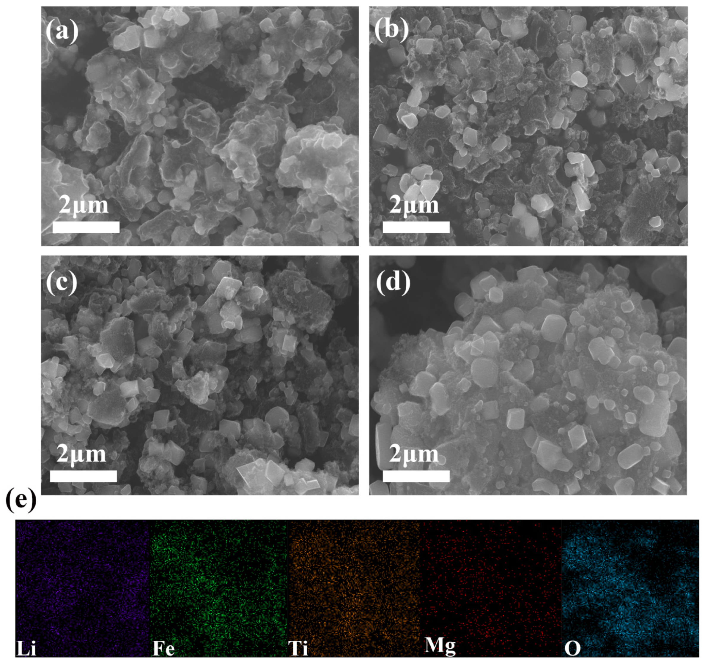
2.1. SEM Analysis of Li2MgxFe1−xTiO4 Samples

SEM was employed to explore the microscopic morphology of the LiFT-Mgx samples. There were no significant changes in the structure (Figure 1a–d). They exhibited a clear calcined body structure, and this was formed by the aggregation of numerous tiny and irregular particles with obvious agglomeration phenomena, and the size of the particles forming the agglomerates ranged from 200 nm to 500 nm. It was declared that Mg doping had little effect on the microscopic morphology of the materials. This phenomenon might be due to the fact that the dopant ions were able to effectively occupy the lattice positions without destroying the symmetry and integrity of the original crystals [12]. Therefore, even if the doped samples showed morphological changes, such as the appearance of new agglomerates or a slight increase or decrease in grain size, these changes were usually localised, controllable and not sufficient to change the overall properties of the material. In addition, these elements (Li, Fe, Ti, Mg, and O) were evenly distributed (Figure 1e). The results confirmed the uniformity and consistent particle size of the synthesized samples, which was crucial for the materials’ properties and applications [13].

2.2. XRD Analysis of Li2MgxFe1−xTiO4 Samples

In order to further analyse the microstructural morphology as well as the difference in phase species of Li2MgxFe1−xTiO4 materials under different doping levels, XRD plots were compared with each other. According to Figure 2a, it could be seen that the main phase of the sample after Mg doping was still a heterogeneous phase of Li2FeTiO4 and Fe3O4 [14,15]. Meanwhile, when the doping content reached X = 0.05, the characteristic peaks of Li2FeTiO4 gradually became shorter and wider. This might be due to the fact that excessive Mg doping amounts could lead to a decrease in the crystallinity of the sample, ultimately leading to a weakening of the characteristic peak strength [16]. In addition, impurity peaks (Fe3O4) existed in the X = 0.05 system. The possible explanation was that excessive doping of Mg2+ ions might cause lattice distortion, altering the local charge distribution. This change might prompt the redistribution of Fe2+ and Fe3+ to form a more stable Fe3O4 structure. It was worth noting that LiFT-Mg0.03 was relatively significant in both crystallinity and purity, which meant the most significant ion dynamics. Moreover, it could be seen that with the increase of doping amount, the position of the diffraction peaks shifted towards the direction of small angle corresponding to the arrow (Figure 2b). The (200) peaks exhibited a shift towards higher angles, moving from 43.7° to 43.4°. This suggested that the incorporation of Mg elements led to changes in the interlayer spacing, lattice parameters, and cell volume. This could be due to the larger ionic radius of Mg2+ [17]. The increased interlayer spacing in LiFT-Mg0.03 was anticipated to enhance the structure for lithium storage, facilitating faster ion movement and boosting kinetic behavior.

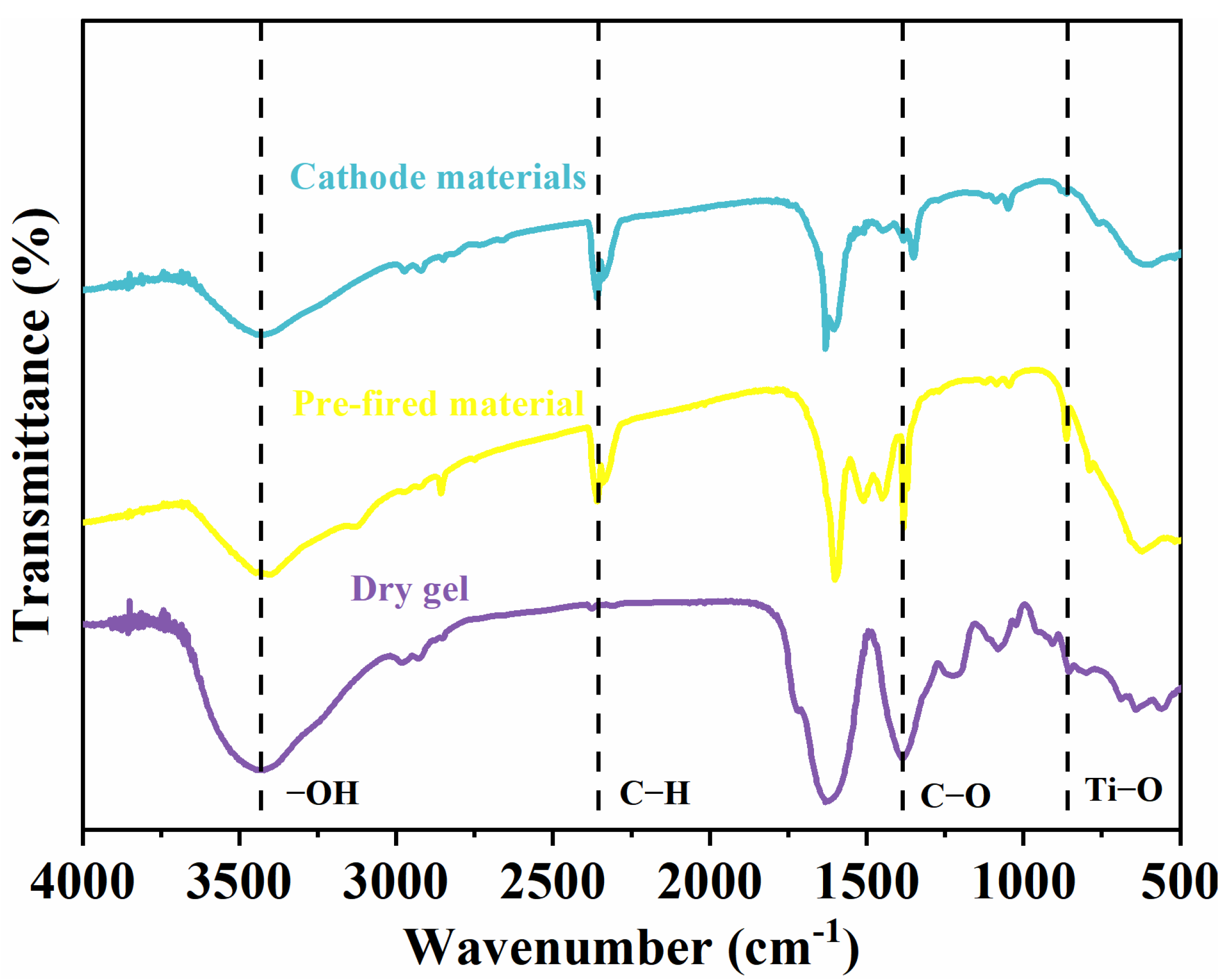
2.3. FTIR Analysis of Li2MgxFe1−xTiO4 Samples

In order to investigate the structure changes of different samples, FTIR was used, as shown in Figure 3. FTIR was performed on the dry gel, pre-fired material, and cathode materials obtained from LiFT-Mg0.03. Peak regions were observed at 860 cm−1, 1000–1600 cm−1, and 3430 cm−1, corresponding to Ti−O, C−O, C−H, and −OH groups, respectively [18]. It could be found that the samples of the three stages were basically similar in terms of peak position, which indicated that the chemical bond had not changed much. However, the strength of the pre-fired samples and the cathode materials in the 1000–1600 cm−1 region was weakened because of the decomposition of esters caused by high-temperature calcination.

2.4. TG-DSC Analysis of Li2MgxFe1−xTiO4 Samples

In order to study the thermal stability of the dry gel of LiFT-Mg0.03 material and its crystallisation process, we decided to carry out TG-DSC analysis (Figure 4). From the figure it can be seen that the whole heating process can be divided into four stages: (1) 25–200 °C; (2) 200–460 °C; (3) 460–680 °C; and (4) 680–1000 °C. In the first stage, about 1.4% of the mass was lost, corresponding to the DSC curve with two absorbing peaks and two exothermic peaks, of which the more obvious absorbing peak at 100 °C corresponded to the loss of water of crystallisation of the compounds; in the second stage, more mass was lost, about 45%, corresponding to the DSC curve with one exothermic peak and two absorbing peaks. One of the absorbing peaks indicated that the thermal decomposition of citric acid occurs to trigger a large amount of weight loss. And the other absorbing peak indicated that the metal salts (e.g., FeCl2, Ti(OC4H9)4, CH3COOLi) had begun to decompose thermally. In the third stage, there was no obvious loss of mass, and the corresponding DSC curve had no obvious heat-absorbing and exothermic peaks. This might be the initial generation of LiFT-Mg0.03 crystals. There was an 8% loss of mass in the fourth stage, and the corresponding DSC curve was relatively flat with no obvious heat-absorbing and exothermic peaks. This stage was the further generation of LiFT-Mg0.03 crystals.

2.5. Valence Analysis of Li2MgxFe1−xTiO4 Samples

For further analysis of the elemental valence states of LiFT and the LiFT-Mg0.03 samples, XAS was organized. Standard Fe2O3 and FeO reference spectra were used to compare with the K-edge of Fe. Both LiFT and the LiFT-Mg0.03 samples displayed signs of Fe existing in a mixed valence state, with valence states of +2.53 for LiFT and +2.61 for LiFT-Mg0.03 (Figure 5a). This phenomenon indicated that the introduction of Mg2+ slightly increased the valence state of the Fe layer, which was conducive to the enhancement of the Fe-O effect and facilitated the rapid migration of lithium ions [19,20,21,22,23]. Additionally, the Ti K-edge XANES spectra revealed that Li2FeTiO4 exhibited no notable changes, suggesting that the Ti valence remained consistently at +4 (Figure 5b).

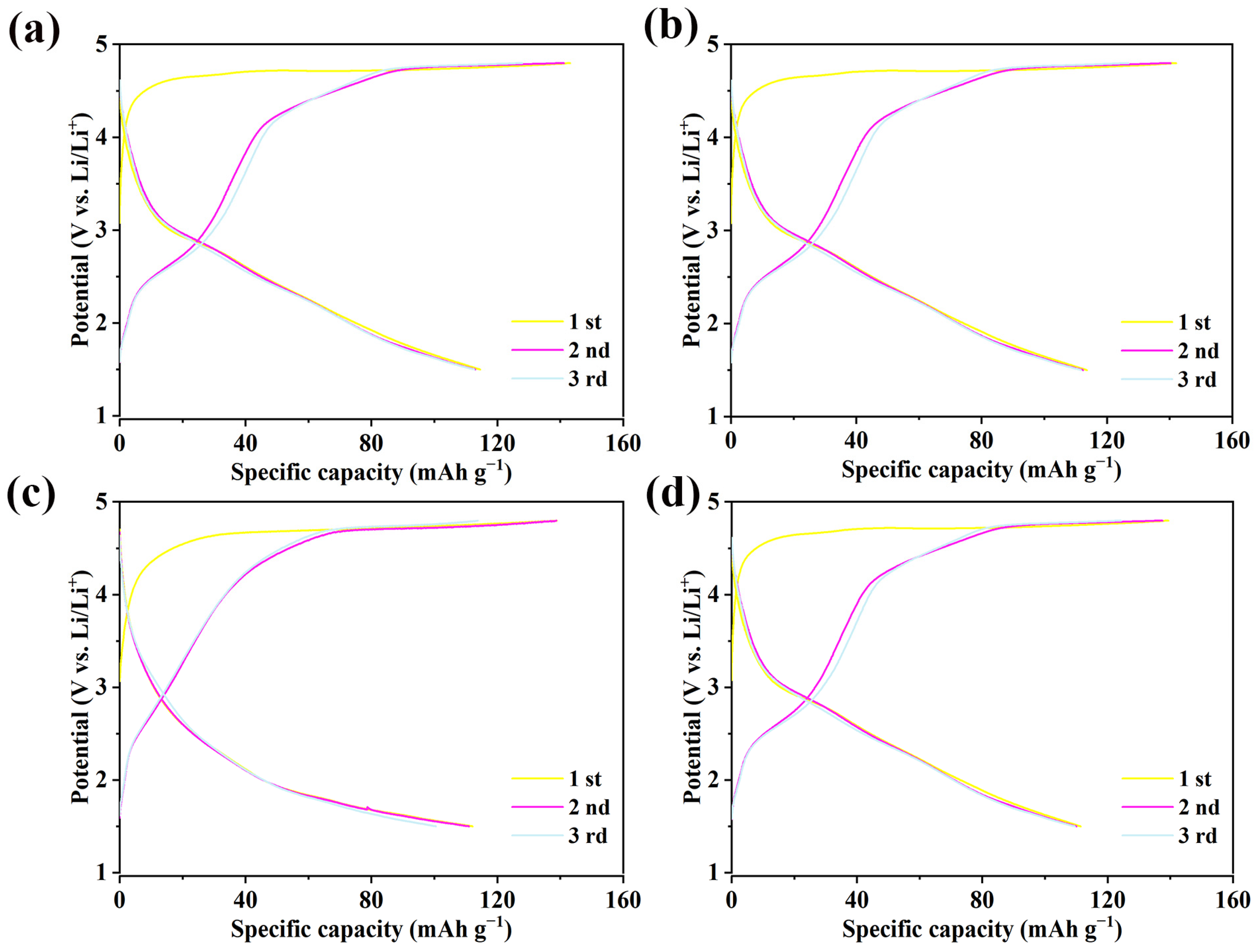
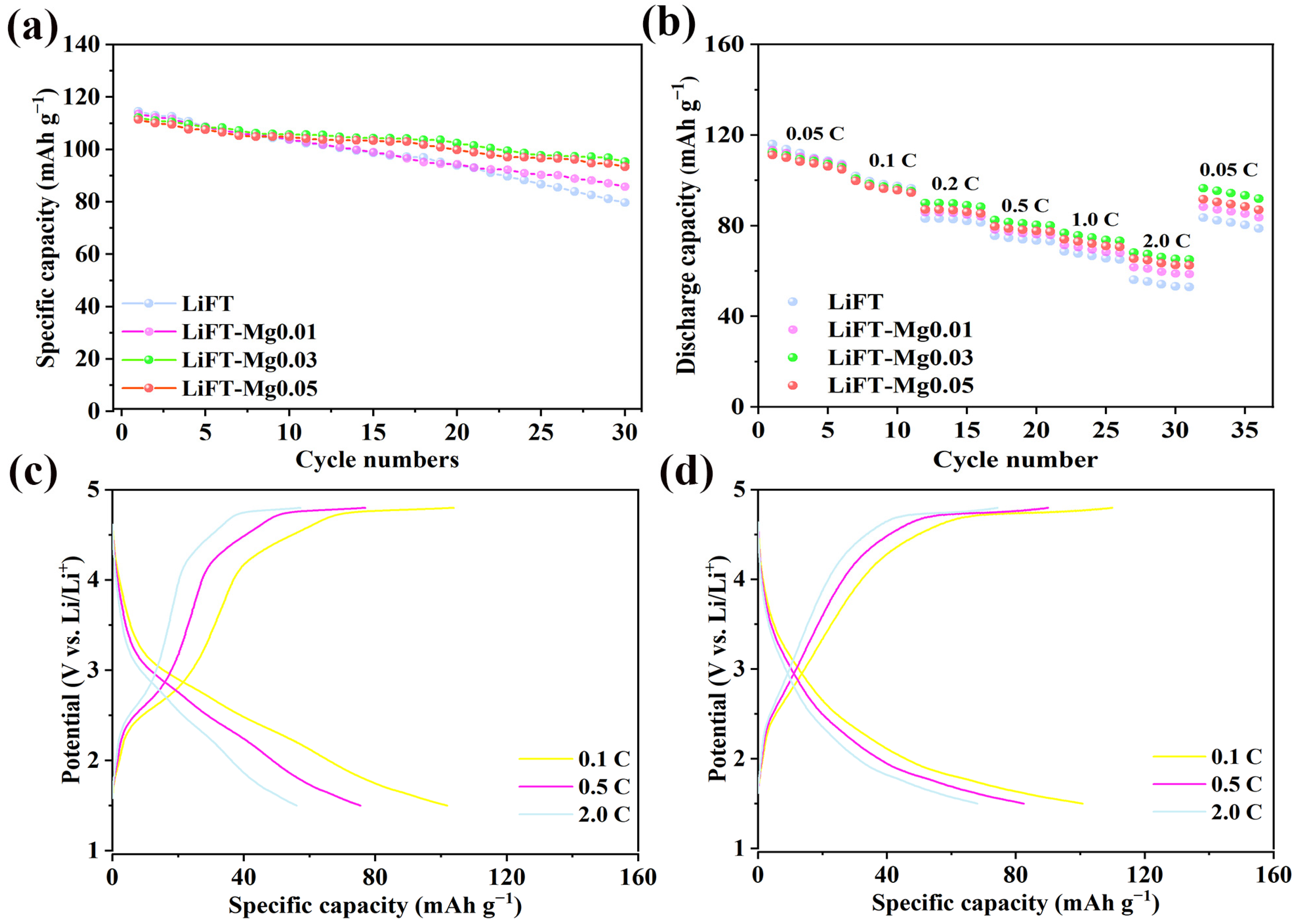
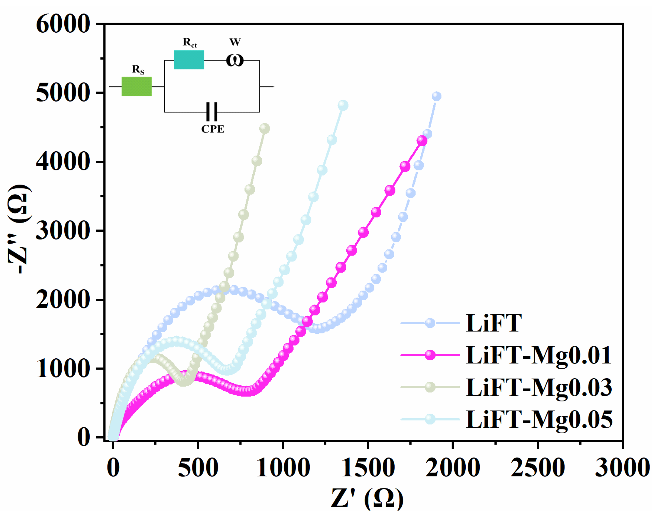
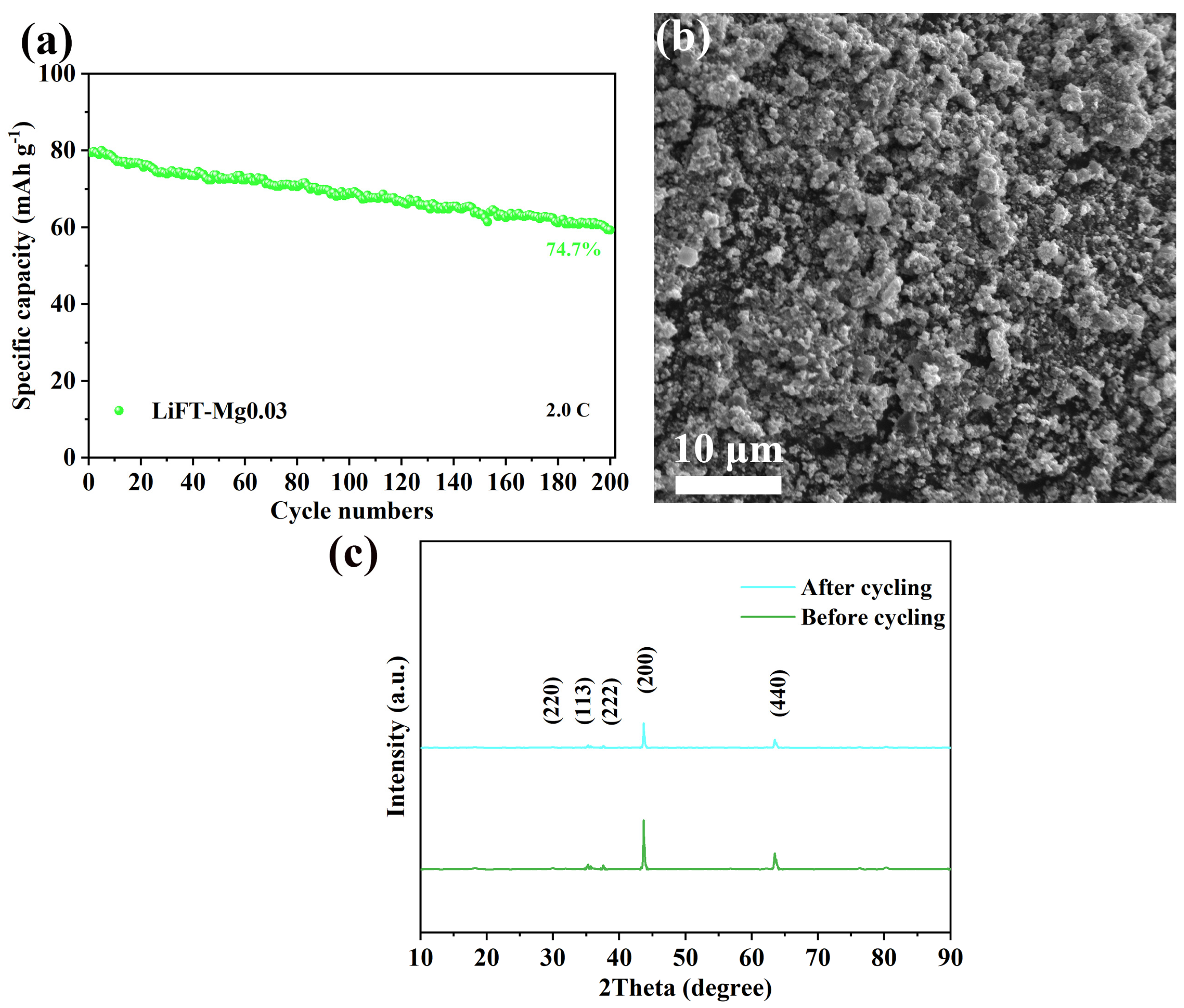
2.6. Electrochemical Properties of Li2MgxFe1−xTiO4 Samples

A series of experiments were carried out to examine how Mg doping influences the electrochemical performance of LiFT, including LiFT-Mg0.01, LiFT-Mg0.03, and LiFT-Mg0.05. The initial capacities were measured at 114.5, 113.6, 112.1, and 111.4 mAh g−1, respectively (Figure 6a–d). Because magnesium is chemically inert, its capacity tends to decay as the magnesium content increases. In addition, the repeatability of the charge curves of doped cathode materials was better than that of undoped materials. As a result, Mg doping helped improve structural stability and promoted the fast transport of lithium ions.
In addition, the samples underwent further testing to evaluate their cycling performance at 0.05 C. At the 30th cycle, the capacities of LiFT, LiFT-Mg0.01, LiFT-Mg0.03, and LiFT-Mg0.05 were measured at 79.7, 85.8, 95.3 and 93.4 mAh g−1, representing 69.6%, 75.5%, 85.0% and 83.8% of their initial capacities, respectively (Figure 7a). The LiFT-Mg0.03 cathode material showed the greatest stability across the charge/discharge cycles. Finally, rate performance was evaluated across various current densities (0.05–2.0 C) (Figure 7b). It was observed that as the current density increased, the capacity of all the samples declined. At 2.0 C, the capacities were 56.1, 61.7, 68.1 and 65.4 mAh g−1, which accounted for 48.4%, 54.4%, 60.6% and 58.1% of their initial values, respectively. After cycling the samples back to 0.05 C, the reversible capacities were recorded at 83.5, 88.4, 96.5 and 91.6 mAh g−1, representing 72.0%, 78.0%, 85.9% and 82.4% of the original capacities. Clearly, the LiFT-Mg0.03 cathode material demonstrated the best rate performance, which could be attributed to its wider layer spacing and improved ion transmission characteristics. This finding was further confirmed by XRD and EIS. Moreover, compared with LiFT, LiFT-Mg0.03 had better charge–discharge characteristics at different current densities (Figure 7c,d). The coulomb efficiency of the two samples was greatly improved compared with Figure 6. Because of the pre-activation, the growth of the CEI film was conducive to a more stable charge and discharge.
In order to investigate the relationship between impedance and Mg doping, the EIS of different doped materials were compared, as shown in Figure 8. The main features of the curves were a semicircle and a straight line [24,25]. The high-frequency semicircle was said to be closely related to charge transfer resistance (Rct) and ion migration dynamics [26]. With the increase in doping amount, the impedance of electrode material decreased first and then increased further. The Rct values for LiFT, LiFT-Mg0.01, LiFT-Mg0.03, and LiFT-Mg0.05 were recorded at 1200.8 Ω, 802.5 Ω, 408.8 Ω and 671.9 Ω (Table 1). These results convincingly expounded that Mg doping upgraded the sodium ion movement, and further supported the optimization design of LiFT-Mg0.03.
In order to better evaluate the effect of a high current environment on LiFT-Mg0.03, we conducted a high current cycle test again. After the study, it was found that LiFT-Mg0.03 still retained 74.4% of the initial value after 200 cycles at 2.0 C (Figure 9a). Then, the morphology and structure of the recycled materials were tested again. After a long cycle, LiFT-Mg0.03 could still maintain its original morphology and crystal structure while the crystallinity decreased after cycling, possibly due to lattice damage caused by long-term charge and discharge (Figure 9b,c). In general, the sample still had the potential for long-term operation with a certain high current.
In order to study the basic history and thermodynamic characteristics of the electrochemical reaction of LiFT-Mg0.03, CV curves were performed at 1.5–4.8 V. It could be noticed that there were still three sets of oxidation peaks and three sets of reduction peaks in Figure 10. And the locations of the peaks in both cycles were strikingly similar, suggesting its favourable electrochemical reversibility. A notable peak appeared in the potential range around 3.0 V, corresponding to the oxidation of Fe2+ to Fe3+, a typical reaction observed during cycling [27]. As the voltage increased to 3.8 V, Fe3+ was further oxidized to Fe4+ [28,29]. These indicated that the battery could store energy reliably while maintaining stability and a long lifespan.

3. Materials and Methods

3.1. Material Preparation

The sol–gel technique was employed for creating Li2MgxFe1−xTiO4 (LiFT-Mgx, x = 0, 0.01, 0.03, 0.05). Li, Fe, Ti, and Mg came from CH3COOLi·2H2O, FeCl2·4H2O, tetrabutyl titanate (Ti(OC4H9)4), and MgCl2·6H2O, respectively. And citric acid was the chelating agent. The raw materials were initially mixed in ethanol at their stoichiometric ratio. Taking LiFT-Mg0.03 as an example, the molar ratio of CH3COOLi·2H2O, Ti(OC4H9)4, FeCl2·4H2O, and MgCl2·6H2O was 2:1:0.07:0.03. So the amount of CH3COOLi·2H2O, Ti(OC4H9)4, FeCl2·4H2O, and MgCl2·6H2O were 0.2040 g, 0.3403 g, 0.0139 g, and 0.0061 g. And the amount of ethanol was 30 mL. Treating the solution with a water bath (65 °C, 5 h) formed a yellow gel. The gel was then further dried to produce a dry gel (120 °C, 12 h). Next, the high-temperature pretreatment (500 °C, 8 h) in argon was performed on the dry ground gel for the first time. This was the pre-fired sample. Finally, the secondary calcination of the pre-fired sample was performed at 650 °C for 8 h. Among them, the calcination rate was 5 °C/min, and it was cooled with the furnace.

3.2. Characterization

A scanning electron microscope (SEM Hitachi S-4800, Hitachi, Japan) was suitable for microstructure analysis. The crystal structure was determined using X-ray diffractometry (XRD, Cu-Kα, 5° min−1 scan rate, 2θ mode, X/Pert Pro 3040/60), Fourier transform infrared spectroscopy (FTIR, 8400S, Shimadzu, Kyoto, Japan), and Mössbauer spectroscopy (MS, 57Co, Shimadzu). Using X-ray absorption spectroscopy (XAS) at the Beijing Synchrotron Radiation Facility (BSRF)’s beamline 4B9A XRD station, we measured the Ti and Fe K-edges to determine elemental valences.

3.3. Electrochemical Measurements

Synthesized materials, acetylene black, and polyvinylidene fluoride (PVDF) were combined in N-methyl-2-pyrrolidinone (NMP) at an 8:1:1 weight ratio to create the cathode slurry. Subsequently, the cathode slurry was coated on an Al foil, wherein the Al foil was a collector. Following this, it underwent overnight drying at 80 °C. Inside a glovebox, the negative shell, Na sheet, separator, cathode material, gasket, shrapnel and positive shell were assembled in order to obtain the 2032 coin battery. In this group, the electrolyte was lithium iron phosphate (KLD-LFP01), and Celgard 2400 was the separator. Using a LAND system, electrochemical properties were evaluated from 1.5 to 4.8 V.

4. Conclusions

In conclusion, Mg-doped Li2MgxFe1−xTiO4 (LiFT-Mgx, x = 0, 0.01, 0.03, 0.05) cathode materials were synthesized using the sol–gel method. The LiFT-Mg0.03 sample exhibited smaller Rct, indicating superior electrochemical kinetics. As a result, the LiFT-Mg0.03 cathode realized impressive specific capacities (112.1 mAh g−1, 0.05 C) and stability (85.0%, 30 cycles). This could be attributed to the improvement in electrochemical kinetics. This study provided fresh insights into the relationship between structural features and performance, which could open new avenues for the development of advanced Li2FeTiO4 cathode materials in future research.

Author Contributions

Conceptualization, P.H. and Y.Q.; methodology, R.H.; software, X.T.; validation, G.L., S.L. and Y.Q.; formal analysis, R.H.; investigation, X.T.; resources, G.L.; data curation, Y.Q.; writing—original draft preparation, P.H.; writing—review and editing, P.H.; visualization, R.H.; supervision, Y.Q.; project administration, S.L.; funding acquisition, Y.Q. All authors have read and agreed to the published version of the manuscript.

Funding

This work was financially supported by the Natural Science Foundation of Hebei Province (E2021501029), and the National Natural Science Foundation of China (52204394).

Data Availability Statement

The original contributions presented in this study are included in the article. Further inquiries can be directed to the corresponding authors.

Conflicts of Interest

The authors declare no competing financial interest.

References

  1. Zhang, G.; Zhu, J.; Dai, H.; Wei, X. Multi-level intelligence empowering lithium-ion batteries. J. Energy Chem. 2024, 97, 535–552. [Google Scholar] [CrossRef]
  2. Wang, J.; Ghosh, T.; Ju, Z.; Ng, M.F.; Wu, G.; Yang, G.; Zhang, X.; Zhang, L.; Handoko, A.D.; Kumar, S.; et al. Heterojunction structure of cobalt sulfide cathodes for high-performance magnesium-ion batteries. Matter 2024, 7, 1833–1847. [Google Scholar] [CrossRef]
  3. Olutogun, M.; Vanderbruggen, A.; Frey, C.; Rudolph, M.; Bresser, D.; Passerini, S. Recycled graphite for more sustainable lithium-ion batteries. Carbon Energy 2024, 6, e483. [Google Scholar] [CrossRef]
  4. Ma, H.; Wang, F.; Shen, M.; Tong, Y.; Wang, H.; Hu, H. Advances of LiCoO2 in cathode of aqueous lithium-ion batteries. Small Methods 2024, 8, 2300820. [Google Scholar] [CrossRef]
  5. Zhao, K.; Yang, Y.; Liu, X.; Wang, Z.L. Triboelectrification-enabled self-charging lithium-ion batteries. Adv. Energy Mater. 2017, 7, 1700103. [Google Scholar] [CrossRef]
  6. Wu, X.; Liu, Y.; Wang, J.; Tan, Y.; Liang, Z.; Zhou, G. Toward circular energy: Exploring direct regeneration for lithium-ion battery sustainability. Adv. Mater. 2024, 36, 2403818. [Google Scholar] [CrossRef]
  7. Bruno, S.R.; Blakely, C.K.; Clapham, J.B.; Davis, J.D.; Bi, W.; Alp, E.E.; Poltavets, V.V. Synthesis and electrochemical properties of novel LiFeTiO4 and Li2FeTiO4 polymorphs with the CaFe2O4-type structures. J. Power Sources 2015, 273, 396–403. [Google Scholar] [CrossRef]
  8. Ma, W.; Tang, Y.; Zhang, Y.; Liu, L.; Tang, B.; Jia, D.; Cao, Y. Cation-disordered Li2FeTiO4 nanoparticles with multiple cation and anion redox for symmetric lithium-ion batteries. Chin. Chem. Lett. 2024, 110346, in press. [Google Scholar]
  9. Tang, Y.; Liu, L.; Zhao, H.; Zhang, Y.; Kong, L.B.; Gao, S.; Li, X.; Wang, L.; Jia, D. Pseudocapacitive behaviors of Li2FeTiO4/C hybrid porous nanotubes for novel lithium-ion battery anodes with superior performances. ACS Appl. Mater. Interfaces 2018, 10, 20225–20230. [Google Scholar] [CrossRef]
  10. Yang, M.; Zhao, X.; Yao, C.; Kong, Y.; Ma, L.; Shen, X. Nanostructured cation disordered Li2FeTiO4/graphene composite as high capacity cathode for lithium-ion batteries. Mater. Technol. 2016, 31, 537–543. [Google Scholar] [CrossRef]
  11. Wu, Z.; Zhang, C.; Yuan, F.; Lyu, M.; Yang, P.; Zhang, L.; Zhou, M.; Wang, L.; Zhang, S.; Wang, L. Ni-rich cathode materials for stable high-energy lithium-ion batteries. Nano Energy 2024, 126, 109620. [Google Scholar] [CrossRef]
  12. Liu, Y.; Li, S.; Gu, Z.Y.; Heng, Y.L.; Lu, H.Y.; Yang, J.L.; Du, M.; Wang, X.T.; Guo, J.Z.; Dong, F.; et al. P/S-orbital hybridization induced by Mg-doping to active Na sites in Na2FePO4F cathode for long-life and high-rate sodium-ion batteries. Energy Storage Mater. 2024, 68, 103319. [Google Scholar] [CrossRef]
  13. Kuzma, M.; Dominko, R.; Meden, A.; Makovec, D.; Bele, M.; Jamnik, J.; Gaberšček, M. Electrochemical activity of Li2FeTiO4 and Li2MnTiO4 as potential active materials for Li ion batteries: A comparison with Li2NiTiO4. J. Power Sources 2009, 189, 81–88. [Google Scholar] [CrossRef]
  14. Chen, R.; Knapp, M.; Yavuz, M.; Ren, S.; Witte, R.; Heinzmann, R.; Hahn, H.; Ehrenberg, H.; Indris, S. Nanoscale spinel LiFeTiO4 for intercalation pseudocapacitive Li+ storage. Phys. Chem. Chem. Phys. 2015, 17, 1482–1488. [Google Scholar] [CrossRef]
  15. Ma, W.; Tang, Y.; Zhang, Y.; Li, X.; Liu, L.; Wang, X.; Cao, Y. Synergistic enhancement of ion/electron transport by ultrafine nanoparticles and graphene in Li2FeTiO4/C/G nanofibers for symmetric Li-ion batteries. J. Energy Chem. 2025, 101, 42–51. [Google Scholar] [CrossRef]
  16. Zhao, S.; Yan, K.; Zhang, J.; Sun, B.; Wang, G. Reaction mechanisms of layered lithium-rich cathode materials for high-energy lithium-ion batteries. Angew. Chem. Int. Ed. 2021, 60, 2208–2220. [Google Scholar] [CrossRef]
  17. Duan, Y.; Ma, Z.H.; Li, L.; Su, G.; Bao, S.; Lu, J.I. Research on sodium storage performance of Cu and Mg doped P2 type layered oxide cathode materials. J. Electrochem. Soc. 2024, 171, 030502. [Google Scholar] [CrossRef]
  18. Chakrabarti, S.; Thakur, A.K.; Biswas, K. Raman and FTIR spectroscopy study of LiFeTiO4 and Li2FeTiO4. Ionics 2016, 22, 2045–2057. [Google Scholar] [CrossRef]
  19. Dang, R.; Qu, Y.; Ma, Z.; Yu, L.; Duan, L.; Lu, W. The effect of elemental doping on nickel-rich NCM cathode materials of lithium ion batteries. J. Phys. Chem. C 2022, 126, 151–159. [Google Scholar] [CrossRef]
  20. Qi, M.; Wang, L.; Huang, X.; Ma, M.; He, X. Surface engineering of cathode materials: Enhancing the high performance of lithium-ion batteries. Small 2024, 20, 2402443. [Google Scholar] [CrossRef]
  21. Chakrabarti, S.; Thakur, A.K.; Biswas, K. Density functional theory study of LiFeTiO4. J. Power Sources 2016, 313, 81–90. [Google Scholar] [CrossRef]
  22. Cao, Q.; Li, Z.; Cai, L.; Liu, S.; Bu, Z.; Yang, T.; Meng, X.; Xie, R.; Wang, X.; Li, Q.; et al. Voltage control of multiple electrochemical processes during lithium ion migration in NiFe2O4 ferrite. ACS Nano 2024, 18, 15261–15269. [Google Scholar] [CrossRef] [PubMed]
  23. Liu, Y.; Chang, C.; Zheng, J. Revealing the role of Mg doping in LiFe0.39Mg0.01Mn0.6PO4/C cathode: Enhanced electrochemical performance from improved electrical conductivity and promoted lithium diffusion kinetics. J. Energy Storage 2024, 91, 112108. [Google Scholar] [CrossRef]
  24. Chen, S.P.; Lv, D.; Chen, J.; Zhang, Y.H.; Shi, F.N. Review on defects and modification methods of LiFePO4 cathode material for lithium-ion batteries. Energy Fuels 2022, 36, 1232–1251. [Google Scholar] [CrossRef]
  25. Yang, L.; Luo, S.; Wang, Y.; Zhan, Y.; Wang, Q.; Zhang, Y.; Liu, X.; Mu, W.; Teng, F. Excess capacity on compound phases of Li2FeTiO4 composite cathode materials synthesized by hydrothermal reaction using optional titanium sources to boost battery performance. Chin. Chem. Lett. 2020, 31, 3200–3204. [Google Scholar] [CrossRef]
  26. Dupre, N.; Cuisinier, M.; Zheng, Y.; Fernandez, V.; Hamon, J.; Hirayama, M.; Kanno, R.; Guyomard, D. Evolution of LiFePO4 thin films interphase with electrolyte. J. Power Sources 2018, 382, 45–55. [Google Scholar] [CrossRef]
  27. Hou, P.; Yang, L.; Wang, Y.; Wang, L.; Li, S.; Luo, S.H. Optimize hydrothermal synthesis and electrochemical performance of Li2FeTiO4 composite cathode materials by using orthogonal experimental design method. Ionics 2020, 26, 1657–1662. [Google Scholar] [CrossRef]
  28. Xu, W.; Zhou, Y.; Ji, X. Lithium-ion-transfer kinetics of single LiFePO4 particles. J. Phys. Chem. Lett. 2018, 9, 4976–4980. [Google Scholar] [CrossRef]
  29. Yue, J.; Xiong, F.; Shadike, Z.; Gao, X.; Chen, J.; Pi, L.; Yuan, Y.; Qu, B.; Adamson, P.; Ma, L.; et al. A layer-structured high entropy oxide with highly reversible Fe3+/Fe4+ redox as advanced cathode material for sodium ion batteries. J. Power Sources 2025, 627, 235735. [Google Scholar]
Figure 1. SEM images of: (a) LiFT; (b) LiFT-Mg0.01; (c) LiFT-Mg0.03; (d) LiFT-Mg0.05; (e) element mapping of LiFT-Mg0.03.
Inorganics 13 00076 g001
Figure 2. (a) XRD images of different samples; (b) enlarged images of different samples.
Inorganics 13 00076 g002
Figure 3. FTIR of LiFT-Mg0.03 at dry gel, pre-fired sample and the cathode material.
Inorganics 13 00076 g003
Figure 4. TG-DSC of LiFT-Mg0.03 at dry gel.
Inorganics 13 00076 g004
Figure 5. Normalized XAS spectra of: (a) Fe K-edge and (b) Ti K-edge of LiFT and LiFT-Mg0.03 samples.
Inorganics 13 00076 g005
Figure 6. Charge/discharge curves of: (a) LiFT; (b) LiFT-Mg0.01; (c) LiFT-Mg0.03; and (d) LiFT-Mg0.05.
Inorganics 13 00076 g006
Figure 7. (a) Cycle performance; (b) rate performance of LiFT, LiFT-Mg0.01, LiFT-Mg0.03, and LiFT-Mg0.05 samples; charge–discharge profiles of (c) LiFT and (d) LiFT-Mg0.03 samples at varied current densities.
Inorganics 13 00076 g007
Figure 8. EIS of LiFT, LiFT-Mg0.01, LiFT-Mg0.03, and LiFT-Mg0.05 samples.
Inorganics 13 00076 g008
Figure 9. (a) Cycle performance at 2.0 C; (b,c) SEM and XRD of LiFT-Mg0.03 after 200 cycles.
Inorganics 13 00076 g009
Figure 10. CV curves of LiFT−Mg0.03 material.
Inorganics 13 00076 g010
Table 1. The fitted impedance (Rs and Rct) for the samples.
LiFTLiFT-Mg0.01LiFT-Mg0.03LiFT-Mg0.04
Rs (Ω)8.3 7.45.86.9
Rct (Ω)1200.8802.5408.8671.9
Disclaimer/Publisher’s Note: The statements, opinions and data contained in all publications are solely those of the individual author(s) and contributor(s) and not of MDPI and/or the editor(s). MDPI and/or the editor(s) disclaim responsibility for any injury to people or property resulting from any ideas, methods, instructions or products referred to in the content.

