Abstract
Nanoparticles of iron and iron oxides, as well as their composites, are of great scientific and technological interest. However, their properties and sustainability strongly depend on the preparation methods. Here, we present an original approach to synthesizing Fe and FeNix metal nanoparticles by exsolution, in a reducing environment at elevated temperatures from perovskite ferrites (La1−xCaxFeO3−γ, CaFeO2.5, etc.). This approach is made possible by the auxiliary reactions of non-reducible A-site cations (in ABO3 notation) with the constituents of reducing compounds (h-BN etc.). The nanoparticles exsolved by our process are embedded in oxide matrices in individual voids formed in situ. They readily undergo redox cycling at moderate temperatures, while maintaining their localization. Fe nanoparticles can be obtained initially and after redox cycling in the high-temperature γ-form at temperatures below equilibrium. Using their redox properties, a new route to producing hollow and layered oxide magnetic nanoparticles (Fe3O4, Fe3O4/La1−xCaxFeO3−γ), by separating the oxidized exsolved particles, was developed. Our approach provides greater flexibility in controlling exsolution reactions and matrix compositions, with a variety of possible starting compounds and exsolution degrees, from minimal up to ~100% (in some cases). The described strategy is highly important for the development of a wide range of new functional materials.
1. Introduction
Nanomaterials based on nanoparticles of transition metals and/or their oxides are of great interest from both scientific and practical viewpoints. Their applications are very diverse and include catalytic, magnetic, electronic, sorption, and pharmaceutical functional materials, utilizing various types of nanoparticles (supported, embedded, individual nanoparticles of various shapes) [1,2,3]. Many transition metal nanoparticles are chemically active and, therefore, suffer from a lack of stability, which is further exacerbated by their tendency for recrystallization, agglomeration, and growth, etc., especially at elevated temperatures. Supported/embedded nanocomposite materials have the potential to combine useful properties of both nanoparticles and matrices and maintain long-term stability and durability [1,3,4]. Moreover, those materials can develop new features due to the synergy between nanoparticles and the support, which is attributed to the intrinsic properties of the components and the strength of their interaction [4,5,6,7].
There are a wide variety of ways to produce these diverse nanoparticle-based nanomaterials [5,8,9]. One of the actively developing strategies for the synthesis of nanocomposite materials with stronger metal nanoparticle–substrate interactions (and, therefore, enhanced functionality and stability) is based on the thermal decomposition of complex oxides under reducing conditions. This kind of decomposition can be complete or partial and, especially the latter, is termed metal exsolution. In this approach, the complex oxides must contain both reducible and non-reducible metals under conditions of synthesis [10,11,12,13]. The main progress in this field is associated with the use of perovskite-related oxides of transition metals. It is a vast family of oxides with various stoichiometry (ABO3, An+1BnO3n+1 Ruddlesden–Popper (RP) phases, etc.), whose crystal structures are based on [AO3] close-packed layers, where the main constituents of A-sites are non-reducible rare-earth or alkaline-earth cations, while B-sites, in the interstices, can contain reducible cations of transition metals (Fe, Co, Ni, Cu, etc.) [14,15]. A series of Ln2O3/M nanocomposites, obtained by complete redox decomposition of the perovskite precursors of easily reducible transition metals (M = Ni, Co, etc.), were reported as metal nanoparticle-supported catalytic materials with enhanced productivity and stability [16,17]. However, the synthesis of nanocomposites by partial redox decomposition of perovskites requires methods to control the processes of metal nanoparticle exsolution and matrix transformations. Several approaches are proposed in the literature to facilitate metal exsolution in this manner [10,11,12,18]. One approach includes modification of the initial oxides, such as introducing an A-site deficiency [19,20], doping of B-sites with easily reduced cations [19,21,22], and promoting the formation of RP phases by adjusting the composition of A-sites [13], as well as others. Another approach is to use special reduction conditions, such as lattice strains, voltage biasing, and plasma assistance, as well as varying the temperature and pO2 [13,18].
Metal reduction and exsolution is accompanied by changes in the parent perovskite matrices, which can occur in different ways. One such change is that the starting A-site-deficient perovskites are converted into stoichiometric ones, with minimal topotactical changes [21,23]. Another possible change is the formation of the corresponding oxides of non-reducible metals (La2O3, etc.) [17]. Yet another change is that the initial ABO3-based perovskites can be transformed into RP phases, with different A to B ratios for some A-site compositions (containing Sr2+, etc.) [13].
Although the metal exsolution process is widely employed to enhance surface properties, it can also be used to modify the bulk properties of functional nanocomposites [24,25,26]. The exsolution at the interior grain and phase boundaries, together with the simultaneous transformation of host oxide matrices, provide a new pathway for the modification of a wide range of electrical, optical, and magnetic properties [25,26].
Overall, metal exsolution is a smart and effective strategy, with great potential for the preparation of new functional materials, with enhanced and unique properties. Its implementation, however, largely depends on the specific parent perovskite oxides and the appropriate reaction conditions [10,13,25]. Consequently, further development of methods for tuning the properties of the resulting nanocomposites, by controlling the exsolution process, is needed.
Herein, we present a novel approach to metal exsolution using perovskite-related ferrites, where B-metal exsolution is promoted by the additional auxiliary reactions involving non-reducible A-site cations. We have explored the behavior of a number of La and Ca-based ferrites in this new type of reaction, resulting in the formation of nanocomposites with nanoparticles embedded in individual voids, which are significantly different from the exsolved materials reported previously. The unique properties of the nanoparticles obtained in this manner, as well as the transformation of oxide matrices, will be discussed. It was shown that exsolved metal nanoparticles can be reversibly transformed into oxides in redox cycling, while maintaining their location inside the matrices. Moreover, the use of the chemical properties of nanocomposite matrices derived from alkaline earth-based ferrites makes it possible to separate and investigate the oxide nanoparticles obtained by the oxidation of exsolved metal nanoparticles.
2. Results and Discussion
2.1. The Main Concept of Metal Exsolution Promoted by Auxiliary Reactions
In this study, the synthesis of Fe-containing nanoparticles and nanocomposites is based on a specially developed process for metal exsolution from complex perovskite-related oxides of reducible transition metals (Fe, Ni, etc.). Our new strategy is to facilitate B-site reducible metal exsolution through additional auxiliary reactions (ARs) of non-reducible A-site (in the ABO3 notation) cations with the constituents of reducing compounds, resulting in new complex oxides. This strategy, in a general simplified form, is described by schematic reaction (1):
ABO3−γ + [Rn] + {H2} → B + AR1ηOy + {H2O} + {R2}
Here, [Rn] is a reducing compound that reduces B cations, and at the same time, some (or all) of its constituents (R1) form new complex oxides with non-reducible A-site cations that do not contain reducible B cations. In general, [Rn] (R1R2, etc.) compounds can have a different chemical nature and aggregate states. For clarity of the explanation, the overall reaction can be nominally split into two consecutive pseudo-reactions, (2) and (3):
ABO3−γ + [Rn] + {H2} → B + AOy1 + ηR1Oy2 + {H2O} + {R2}
AOy1 + ηR1Oy2 → AR1ηOy
Chemical reactions for the formation of complex oxides containing R1 and non-reducible A-site cations (1b type) are designated here as auxiliary reactions. Curly brackets {} denote possible compounds. The reaction proceeds at elevated temperatures and under low pO2 conditions, which are required for the formation and preservation of the B components in metal form. An important feature of reaction (1) is that the main source of oxygen for the formation of the resulting oxides is the initial oxides. This imposes limitations on the possible ratios of R1 and A cations in the resulting complex oxides. If the initial oxides include two or more different B cations, then reaction (1) will be more complex depending on the B cation properties, as shown schematically below:
AB’χB″ψO3−γ + [Rn] + {H2} → B’ + {B″} + AR1ηOy + AB’χ−ξB″ψ+ϕO3−β + {H2O} + {R2}
Reaction (4) illustrates that all the different B cations can be exsolved to various degrees, or that the irreducible or less reducible ones can remain in perovskite oxides. The exsolved metals can also form alloys.
2.2. LaFeO3 and Ca2Fe2O5-Based Nanocomposites
For LaFeO3 as a starting material and hexagonal BN as a reducing compound, the A-site cation AR (ACAR)-promoted exsolution can be written as reaction (5) (for clarity purposes, along with the nominal pseudo-reactions (6) and (7)):
LaFeO3 + BN → Fe + LaBO3 + 1/2N2
{2LaFeO3+ 2BN → 2Fe + La2O3+ B2O3 + N2}
{La2O3 + B2O3 → 2LaBO3}
Herein, the processes involving reaction (5) were carried out at elevated temperatures of 700–750 °C, in a reducing atmosphere, provided by a 10% H2/Ar flow. Although hydrogen is not formally involved in the reaction, its role here is to maintain low pO2 conditions, essential for the existence of metal Fe nanoparticles. The formation of lanthanum borate LaBO3 provides an additional driving force for the reduction of LaFeO3 and decreases the reaction temperature compared to a reduction with hydrogen. The specified temperatures of reaction (5) are below the decomposition temperature of LaFeO3 in a hydrogen-containing atmosphere, which is reported to be >850 °C [27,28]. Thus, its decomposition, described by reaction (3), does not occur under these conditions.
LaFeO3 + 3/2H2 → Fe + 1/2La2O3 + 3/2H2O
It is important to maintain reaction (5) as a main process. It should be noted that the higher temperature stability under reducing conditions makes ferrites more preferable starting materials compared to other perovskite-like compounds of reducible transition metals (cobaltites, nickelates, cuprates, etc.) [27].
Moreover, h-BN has a number of properties making it suitable for reactions of type (1, 5). First of all, it has decent reactivity in reactions of type (1, 4) with rare-earth (La, Y, etc.) and alkali-earth (Ca, Sr, etc.) perovskite-related ferrites. At the same time, it is exceptionally stable in inert and reducing atmospheres, and is also quite resistant to oxidation at moderate temperatures in air.
Figure 1 shows the powder XRD patterns of the LaFeO3 ferrite-based samples after interaction with h-BN at ~750 °C with different amounts of exsolved Fe, depending on the LaFeO3/h-BN ratio. As the reaction proceeds, the peaks corresponding to LaBO3 and metal Fe appear in patterns, which are consistent with reaction (5) (Figure 1(a1)). The metal Fe peaks are distinguishable, but they strongly overlap with the LaBO3 ones. The corresponding Mössbauer spectra are shown in Figure 1(b1,b2). Each of the spectra consist of two magnetically split sextet components and a paramagnetic singlet component. All the components are well resolved and do not broaden. According to their hyperfine parameters (Table 1), the first of two sextets with an isomer shift (δ) of 0.37 mm s−1 and a hyperfine magnetic field (Hhf) of 52.4 T correspond to LaFeO3 and the second, with δ ~0 mm s−1 and Hhf = 33 T, correspond to αFe. The paramagnetic singlet, according to its hyperfine parameters (δ~−0.1 mm s−1 at 298 K), corresponds to metal γFe. Moreover, γFe is a high-temperature paramagnetic form, with a close-packed fcc crystal structure. It is important to note that γFe is metastable at temperatures below 910 °C [29], while the synthesis temperature was ~750 °C. The metal γFe nanoparticles, however, may be undetectable in the XRD patterns (Figure 1(a2,b3)). The SEM images of LaFeO3 after the ACAR exsolution display smooth surfaces, without distinguishable metal Fe nanoparticles distributed on them (Figure 2a). Figure 2b,c shows typical TEM images of such samples. For the samples at the low or moderate extent of reaction (Figure 2b,c), the images reveal agglomerated grains of different contrast, probably due to variations in thickness, but exsolved metal Fe particles are not clearly distinguishable. For the samples at the high extent of reaction >40%, obtained after prolonged heating for more than 15 h, the metal Fe particles are also largely undistinguishable, but some whisker-like metal Fe agglomerates are visible (Figure 2d) in small amounts with respect to the reaction extent. Additionally, the EDX analysis revealed numerous La-rich oxide grains, which, according to the XRD analysis, are actually LaBO3, since boron is undetectable. Therefore, the metal Fe particles are embedded in the oxide matrix after the ACAR-promoted exsolution, which makes them hard to distinguish, except for the formation of whiskers, if any.
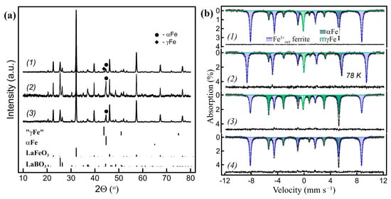
Figure 1.
(a) Powder XRD patterns of the LaFeO3/h-BN-derived nanocomposites: (a1) 29% of the total Fe amount exsolved, where 11% is in γ form; (a2) 54% of Fe exsolved (8% γFe); (a3) sample (a1) oxidized at 300 °C and subsequently reduced at 700 °C, all 29% of Fe exsolved is in α form (all the Fe contributions were evaluated by Mössbauer spectroscopy). (b) Corresponding Mössbauer spectra: (b1,b2) of sample (a1) at RT and 78 K, respectively; (b3) of sample (a2); (b4) of sample (a3) at RT.

Table 1.
Hyperfine parameters of Mössbauer spectra of the LaFeO3/h-BN-derived nanocomposites measured at RT (except Figure 1(b2) at 78 K): δ—isomer shift, ΔEQ—quadrupole splitting, H—hyperfine magnetic field, A—relative area, Γ—linewidth.
Table 1.
Hyperfine parameters of Mössbauer spectra of the LaFeO3/h-BN-derived nanocomposites measured at RT (except Figure 1(b2) at 78 K): δ—isomer shift, ΔEQ—quadrupole splitting, H—hyperfine magnetic field, A—relative area, Γ—linewidth.
| Sample | Component | δ (mm s−1) ±0.01 | ΔEQ (mm s−1) ±0.01 | H (T) ±0.1 | A (%) ±0.5 | Γ (mm s−1) ±0.01 | Comments |
|---|---|---|---|---|---|---|---|
| In Figure 1(b1) | s11 | 0.37 | −0.07 | 52.4 | 71 | 0.26 | Fe3+ oct. in LaFeO3 |
| s21 | −0.01 | −0.01 | 33.0 | 18 | 0.24 | αFe | |
| d11 | −0.10 | 0.00 | - | 11 | 0.25 | γFe | |
| In Figure 1(b2) 78 K | s12 | 0.48 | −0.07 | 56.2 | 71 | 0.25 | Fe3+ oct. in LaFeO3 |
| s22 | 0.11 | 0.01 | 33.8 | 18 | 0.25 | αFe | |
| d12 | 0.01 | 0.00 | - | 11 | 0.25 | γFe | |
| In Figure 1(b3) | s13 | 0.37 | −0.07 | 52.4 | 46 | 0.27 | Fe3+ oct. in LaFeO3 |
| s23 | 0.00 | 0.00 | 33.0 | 45 | 0.24 | αFe | |
| d13 | −0.10 | 0.00 | - | 8 | 0.25 | γFe | |
| In Figure 1(b4) | s15 | 0.37 | −0.07 | 52.3 | 72 | 0.25 | Fe3+ oct. in LaFeO3 |
| s25 | 0.00 | 0.00 | 33.0 | 28 | 0.24 | αFe | |
| In Figure 3(1) | s123 | 0.37 | −0.06 | 52.4 | 68 | 0.27 | Fe3+ oct. in LaFeO3 |
| s223 | 0.00 | 0.01 | 33.1 | 23 | 0.23 | αFe | |
| d123 | −0.10 | 0.00 | - | 9 | 0.26 | γFe | |
| In Figure 3(2) | s124 | 0.37 | −0.07 | 52.2 | 70 | 0.26 | Fe3+ oct. in LaFeO3 |
| s224 | −0.01 | 0.01 | 33.0 | 17 | 0.21 | αFe | |
| d124 | −0.10 | 0.00 | - | 13 | 0.23 | γFe | |
| In Figure 3(3) | s125 | 0.37 | −0.07 | 52.2 | 71 | 0.25 | Fe3+ oct. in LaFeO3 |
| s225 | 0.35 | −0.17 | 51.0 | 5 | 0.33 | Fe3+ oct. in αFe2O3 | |
| s325 | 0.00 | 0.01 | 33.0 | 23 | 0.23 | αFe | |
| d125 | −0.10 | 0.00 | - | 1 | 0.26 | γFe | |
| In Figure 3(4) | s126 | 0.37 | −0.07 | 52.2 | 69 | 0.26 | Fe3+ oct. in LaFeO3 |
| s226 | 0.00 | 0.00 | 33.0 | 30 | 0.22 | αFe | |
| d126 | −0.12 | 0.00 | - | 1 | 0.25 | γFe | |
| In Figure 3(5) | s127 | 0.37 | −0.08 | 52.3 | 70 | 0.25 | Fe3+ oct. in LaFeO3 |
| s227 | 0.38 | −0.18 | 51.4 | 30 | 0.25 | Fe3+ oct. in αFe2O3 | |
| In Figure 3(6) | s128 | 0.37 | −0.06 | 52.2 | 70 | 0.26 | Fe3+ oct. in LaFeO3 |
| s228 | 0.00 | 0.00 | 33.0 | 14 | 0.21 | αFe | |
| d128 | −0.10 | 0.00 | - | 16 | 0.24 | γFe |

Figure 2.
SEM and TEM images of the LaFeO3/h-BN-derived nanocomposites: (a,b) SEM and bright field (BF) TEM images of the nanocomposites with ~45% of Fe total exsolved; (c,d) high-angle annular dark-field scanning TEM (HAADF-STEM) image and energy-dispersive X-ray (EDX) elemental analysis in selected locations of the nanocomposites with ~12% of Fe total (~10% γFe); (d) formation of the Fe whisker (w) in sample (a,b).
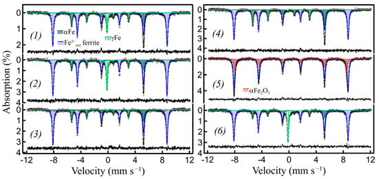
Figure 3.
RT Mössbauer spectra of the LaFeO3/h-BN-derived nanocomposites during redox cycling: (1) as prepared with 32% of Fe exsolved (~9% γFe); (2) sample (1) after consecutive oxidation (air, 500 °C) and reduction (10% H2/Ar, 700 °C) (~30% of Fe total, ~13% γFe); (3) sample (2) after oxidation at 300 °C in air (~23% αFe, ~1% γFe, ~5% αFe2O3); (4) after reduction of sample (3) (10% H2/Ar, 700 °C) (~30% αFe); (5) after oxidation of sample (4) (air, 500 °C) (~30% αFe2O3); (6) after reduction (10% H2/Ar, 700 °C) of sample (5) (~30% of Fe total, ~16% γFe).
This is rather different from the metal exsolution from the A-site-deficient perovskites or the high-temperature hydrogen reduction of stoichiometric perovskite oxides reported previously, where the exsolved metal nanoparticles are typically clearly visible on the surfaces of oxide matrixes [10,11,12,13]. In these processes, the reducible metal cations migrate toward the outer and inner grain surfaces, which are exposed to the reducing environment, and reduce to metal, with subsequent agglomeration, grain growth, etc. The oxide matrices, in turn, undergo shrinkage because of a loss of oxygen and metal constituents, promoting socketing of the exsolved nanoparticles [5,10,12,23]. In our ACAR-promoted exsolution process, metal reduction/exsolution is accompanied by the formation of other complex oxides of two or more elements instead of the initial perovskite oxide, even those of lower density, i.e., LaBO3 vs. LaFeO3. Their formation begins in the contact areas between the initial ferrite grains and the reducing reagents. These newly formed Fe-free oxides (viz. LaBO3) on the top of the initial perovskite grains presumably create a diffusion barrier for the Fe species. Consequently, the exsolved metal Fe nanoparticles do not appear on top of the oxide grain surfaces, but instead localize underneath their surfaces in generated in situ voids.
Perovskite-like ferrites of alkaline-earth elements, such as Ca2Fe2O5 and Sr2Fe2O5, can also be used in reaction (1, 4) to produce metal nanoparticle-bearing composites. Because Ca is lighter than La and Sr, it may be more favorable for microscopic investigations in terms of the nanoparticle–matrix contrast. As stated above, the starting ferrite is the main source of oxygen for the formation of the resulting oxides in ACAR-promoted exsolution processes involving reaction (1, 4). Consequently, in the case of La ferrite, other La borates, such as LaB3O6, cannot be formed from the LaFeO3 precursor due to a lack of oxygen. For Ca2Fe2O5 and h-BN as starting materials, the formation of several Ca borates is possible, viz. Ca2B2O5 and Ca3B2O6 (without/with CaB2O4). The powder XRD patterns of Ca2Fe2O5 after the ACAR-promoted exsolution reactions with h-BN and the corresponding Mössbauer spectra are shown in Figure 4. According to Figure 4(a2), the main complex oxide product is Ca3B2O6 and, therefore, the primary reaction can be written as follow:
3Ca2Fe2O5 + 4BN + 3H2 → 6Fe + 2Ca3B2O6 + 2N2 + 3H2O
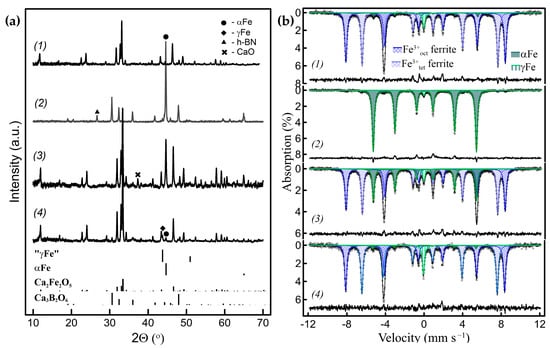
Figure 4.
(a) Powder XRD patterns and, (b), corresponding Mössbauer spectra of the Ca2Fe2O5/h-BN-derived nanocomposites with different amounts of metal Fe exsolved: (1) 7% of the total Fe amount exsolved, where 4% is in γ form; (2) 97% of Fe exsolved (2% γFe); (3) 28% of Fe exsolved (3% γFe); (4) after oxidation–reduction of sample (3), 10% of Fe exsolved (7% γFe).
Hydrogen, in addition to maintaining the low pO2, reacts with excessive oxygen in this case. It is worth noting that no diffraction peaks corresponding to Ca3B2O6 and/or other possible resulting oxides were observed at the low extent of reaction, indicating that the oxide products were X-ray amorphous (Figure 4(a1)). Ca2Fe2O5 is more active in this type of reaction compared to LaFeO3 and is less stable in reducing conditions as well, so minor additional peaks of CaO can be observed in the patterns of some samples depending on the preparation and reduction conditions (Figure 4(a3)). The Mössbauer spectra of the Ca2Fe2O5-derived samples are shown in Figure 4b. The spectra are comprised of three magnetically split sextet components and a paramagnetic singlet component. The Ca2Fe2O5 (=CaFeO2.5) has a brownmillerite structure, which is oxygen deficient compared to ABO3 perovskites with fully ordered oxygen vacancies at room temperature, where Fe3+ cations equally occupy distorted octahedral and tetrahedral oxygen polyhedra. Consequently, two of the sextets of nearly equal spectral contributions, according to their hyperfine parameters, correspond to the brownmillerite subspectrum, i.e., Fe3+tet (δ~0.19 mm s−1 and Hhf = 43.4 T) and Fe3+oct (δ~0.37 mm s−1 and Hhf = 51.2 T) in Ca2Fe2O5. The third sextet (δ~0 mm s−1 and Hhf = 33 T) and a singlet (δ~−0.1 mm s−1) correspond to metal Fe in α and γ forms, respectively, i.e., to the metal Fe subspectrum (Table S2). Like in the LaFeO3 case, at ~650–730 °C, the temperatures during the ACAR-promoted exsolution process were much lower than 910 °C. Both the Fe forms can be distinguished in the powder XRD patterns (Figure 4a). Similar to the previous case, the SEM images of the Ca2Fe2O5-derived samples display smooth surfaces, without distinguishable metal Fe particles (Figure 5a). The TEM images (Figure 5b,c) show agglomerates of different contrasts, without metal Fe particles being clearly visible on the surfaces. At the same time, a small number of Fe whiskers can be observed in some samples (Figure 5d). However, as it follows from Figure 5c, the EDX mapping in several locations shows areas of Fe segregation, which, taking into account the distributions of other elements, can be identified as Fe-embedded nanoparticles. These exsolved, embedded Fe nanoparticles, identified by the EDX analysis, were about 15–25 nm in size. The EDX analysis also displays Ca-rich O-containing agglomerates (i.e., Ca3B2O6, etc.).
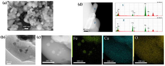
Figure 5.
SEM and TEM images of the Ca2Fe2O5/h-BN-derived nanocomposites with ~23% of metal Fe exsolved (~9% γFe): (a) SEM image; (b,c) BF TEM and HAADF-STEM images with the corresponding EDX compositional map; (d) HAADF-STEM image, with EDX analysis of the Fe whisker.
The data show that the Ca2Fe2O5/h-BN system demonstrates similar behavior to the LaFeO3/h-BN system in the exsolution reactions facilitated by ACARs. In both the systems, the exsolved metal Fe nanoparticles, which can be determined by EDX analysis, are mostly located within oxide matrices, consisting of initial ferrites and newly formed iron-free borates, in the generated in situ voids. Presumably, the reaction zones and, hence, the adjacent voids are somehow connected to the low pO2 environment, otherwise, in most cases, the metal reduction reaction will not proceed to any significant extent. Metal Fe in the exsolved nanoparticles can exist in two forms, namely metastable at temperatures <910 °C γFe and stable αFe, the latter can also form whiskers in some cases. The interior particle growth in a confined space in voids appears to be a key factor, along with a nanosized dimension, for the γFe formation at temperatures well below 910 °C. The fcc close-packed crystal structure of γFe is denser than the bcc structure of α(δ)Fe [30,31], so that the compressive strain developed when the particles of nano-scale dimensions grow under confined conditions is conducive to the formation of γFe nanoparticles and their subsequent stabilization upon cooling. The strain-induced formation of γFe nanoparticles, smaller than ~20 Å, under confined conditions in oxide matrices (Al2O3, MgO), which are stable at an ambient temperature, has been reported previously [32,33]. The stabilization of γFe was also observed in iron coatings produced by arc plasma deposition on porous alumina substrates, when Fe was localized inside pores with a diameter <160 nm [34]. Note that in this case, the deposited Fe layers only covered the inner walls of the pores and did not completely fill their interior space, leaving central gaps.
The γFe/αFe ratio depends on the reaction conditions and extent: the contributions of γFe are larger in the initial stages and at the low extent of reactions. However, the nanocomposites containing only γFe have not been obtained using individual Ca2Fe2O5 or LaFeO3 ferrites. Ca2Fe2O5 is more active during the described process than LaFeO3 and reacts at lower temperatures, and the reaction can proceed almost completely, whereas for LaFeO3, its extent is limited to ~50–60% (based on the Fe content in coexisting phases obtained from the Mössbauer spectra).
2.3. ACAR-Promoted Metal Exsolution Using the Substituted Ferrites
The properties of Ca2Fe2O5 or LaFeO3 ferrites can be significantly modified by substitutions. Accordingly, the effect of cation substitution on ACAR-promoted metal exsolution and γFe formation was investigated. Rare-earth and alkaline-earth ABO3−γ perovskite ferrites allow substitution in both A- and B-sites and a wide variation in oxygen content of 0 ≤ γ ≤ 0.5 [14,15]. Figure 6b shows the powder XRD patterns of A and B double-substituted compounds, Ca1.4Y0.6Fe1.8Zn0.2O5.2 (=Ca0.7Y0.3Fe0.9Zn0.1O2.6), after ACAR-promoted exsolution using h-BN. Y was chosen as the lightest rare-earth 3+ cation. The Ca1-xYxFeO3−γ solid solutions have not been studied in detail in the literature, but for our process it is important that they belong to a pseudobinary system, i.e., no additional phases other than the perovskite solid solutions coexist. The solubility ranges from both the Ca side (the brownmillerite type solid solutions with oxygen excess) and the Y side (the LaFeO3−γ type ones with mainly disordered oxygen vacancies) are not well defined and, presumably, depend on the temperature [35]. Similar to the case of unsubstituted Ca ferrite, the resulting borates can only be correctly identified at relatively large reaction extents, such as in the sample in Figure 6(b2), with ~29% of Fe exsolved, according to the Mössbauer spectrum shown in Figure 6(a2). The XRD phase analysis revealed that substitution with Y increases the number of oxide products formed, and the ACAR-promoted exsolution process in this case can be written in a simplified form as follows:
Ca0.7Y0.3Fe0.9Zn0.1O2.6 + BN + H2 → Fe + Ca3B2O6 + Y2O3 + Ca0.7−zY0.3+zFe0.8−βZn0.1+βO2.6+γ + {Zn5B4O11} + N2 + H2O
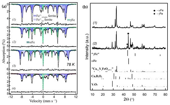
Figure 6.
(a) RT Mössbauer spectra of the Ca0.7Y0.3Fe0.9Zn0.1O2.6/h-BN-derived nanocomposites with different amounts of metal Fe exsolved: (a1) 3.5% of γFe exsolved; (a2) 29% of Fe exsolved (~9% γFe); (a3) the same sample (a2) measured at 78 K; (a4) after oxidation–reduction of sample (a2), 18.5% of Fe exsolved (14% γFe). (b) Powder XRD patterns, (b1) of the initial Ca0.7Y0.3Fe0.9Zn0.1O2.6 ferrite and, (b2) of sample (a2).
The main oxide products are Ca3B2O6 and Y2O3 (Zn5B4O11 could be a minor phase). The Mössbauer spectra (Figure 6(a2,a3)) show that 29% of the Fe total content was exsolved in this sample, where γFe accounted for ~9% and αFe for 20%. The substitution manifests itself in a significant broadening of lines in the Mössbauer spectra, due to the introduction of local distortions and the disruption of the magnetic superexchange interactions. Consequently, the components of the brownmillerite subspectrum that correspond to the tetrahedral and octahedral plus pentagonal positions in the ferrite structures were fitted with combinations of several Zeeman sextets. Sextets with δ~0.34–0.37 mm s−1 and Hhf~49–51 T correspond to Fe3+ cations in octahedral and pentagonal positions (poorly resolved at RT), while those with δ~0.18–0.20 mm s−1 and Hhf ~40–43 T correspond to the tetrahedral ones. The two other components with narrow lines correspond to the metal Fe subspectrum, comprising of the αFe sextet with δ~0 mm s−1 and Hhf ~33 T and the γFe singlet with δ~−0.1 mm s−1. The Mössbauer measurements at 78 K result in the narrower lines of the components, but the spectral contributions of the subspectra remain about the same. At a lower exsolution level of ~3–6%, all metal Fe was in the γ form (Figure 6(a1), Table S3). The TEM images of the latter samples are shown in Figure 7. Similar to the unsubstituted Ca2Fe2O5-derived samples, it was difficult to differentiate the Fe particles among the agglomerates with different contrasts. However, the Fe nanoparticles <50 nm in size embedded in the oxide matrix were clearly identified by the EDX analysis and mapping (Figure 7a,c). The HAADF-STEM images, together with the Fourier transform imaging, confirmed that the exsolved nanoparticles are metallic γFe (Figure 7b). The EDX mapping also shows some degree of Y and O segregation on the scale of tens of nanometers, which is consistent with the XRD phase analysis.
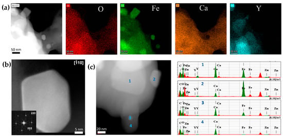
Figure 7.
(a) HAADF-STEM images with the corresponding EDX compositional maps of the Ca0.7Y0.3Fe0.9Zn0.1O2.6/h-BN-derived nanocomposites with 3.5% of γFe exsolved (Figure 6(a1)). (b) [] HAADF-STEM image of the γFe nanoparticle, along with the Fourier transform. (c) HAADF-STEM image with EDX analysis of other Ca0.7Y0.3Fe0.9Zn0.1O2.6/h-BN-derived nanocomposites with 6% of γFe exsolved.
Since Ca is more active in the exsolution reactions than Y, the remaining Ca–Y ferrite can also be enriched in Y despite the formation of Y2O3. This can be seen from the spectra of the samples with high degrees of exsolution, as shown in Figure S1 and Table S4. They reveal that the contributions of spectral components corresponding to Fe3+ in tetrahedral coordination decrease significantly because of the transformation of Ca ferrite-based Ca1−xYxFeO3−γ solid solutions with x = 0.3 to Y ferrite-based solid solutions (presumably with x > 0.6 [35]).
Preferable formation of Ca-rich borates was similarly observed for the La-substituted Ca1−xLaxFeO3−γ starting ferrites. This system is also pseudobinary. Within this system, the Ca2LaFe3O8 Grenier phase, with a crystal structure intermediate between brownmillerite and perovskite types, was reported. In addition, the formation of microdomains of close compositions is possible at different values of x and γ [36,37,38]. The main oxide product in ACAR-promoted exsolution reactions of Ca–La ferrites with h-BN is Ca3B2O6, like for Ca0.7La0.3FeO2.65 in Figure 8(a2,a3)), while the formation of La2O3 was not observed. At higher exsolution degrees, double borate Ca3La3(BO3)5 was additionally formed (Figure 8(a3)). Since La is retained more in the Ca0.7-zLa0.3+zFeO2.65+δ solid solution, its content increases, as does the oxygen index value. At some level of La content, the resulting ferrite solid solution loses oxygen vacancy ordering, i.e., it becomes the La0.3+zCa0.7−zFeO3−γ type perovskite-like solid solution. This is reflected in the Mössbauer spectra as the disappearance of Fe3+ tetrahedral spectral components (Figure 8(b2), Table S5). A simplified reaction is shown in (11):
Ca0.7La0.3FeO2.65 + BN + H2 → Fe + Ca3B2O6 + La0.3+zCa0.7–zFeO3−γ + {Ca3La3(BO3)5} + N2 + H2O
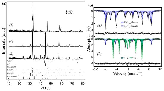
Figure 8.
(a) Powder XRD patterns of the Ca0.a0.3FeO2.65/h-BN-derived nanocomposites with different amounts of metal Fe exsolved: (a1) the initial Ca0.7La0.3FeO2.65 ferrite; (a2) 66% of Fe exsolved (2% γFe); (a3) 76% of Fe exsolved (8% γFe). (All Fe contributions were evaluated by Mössbauer spectroscopy). (b) Mössbauer spectra (b1) of the initial Ca0.7La0.3FeO2.65 ferrite; (b2) of sample (a3).
In the case of LaFeO3-based compounds, the substitution of Fe3+ cations by non-reducible cations can also lead to the formation of γFe exclusively. Figure 9 shows that the Zn-substituted solid solution, LaFe0.8Zn0.2O2.9, reacts with h-BN, according to the simplified reaction:
LaFe0.8Zn0.2O2.9 + BN → Fe + LaBO3 + LaFe0.8−βZn0.2+βO3−γ + N2 + {ZnO}
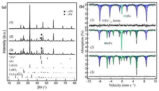
Figure 9.
(a) Powder XRD patterns and (b) corresponding RT Mössbauer spectra of the nanocomposites obtained by the ACAR exsolution from Zn-substituted LaFeO3: (1) from LaFe0.8Zn0.2O2.9/h-BN with ~8% of γFe exsolved; (2) from La0.8Ca0.2Fe0.8Zn0.2O2.8/h-BN with ~50% of Fe exsolved, where ~20%—γFe; (3) sample (2) after grinding in a mortar.
At ~8% of the total metal Fe content, all of the exsolved Fe is in the γ form (Figure 9(b1), Table S5). The TEM EDX mapping of this LaFe0.8Zn0.2O2.9-derived sample with ~8% of γFe exsolved, allowed for the identification of the embedded Fe metal nanoparticles (Figure 10a). The HAADF-STEM images, together with the Fourier transform imaging, confirmed that the exsolved nanoparticles are highly twinned metal γFe nanocrystals (Figure 10b,c).
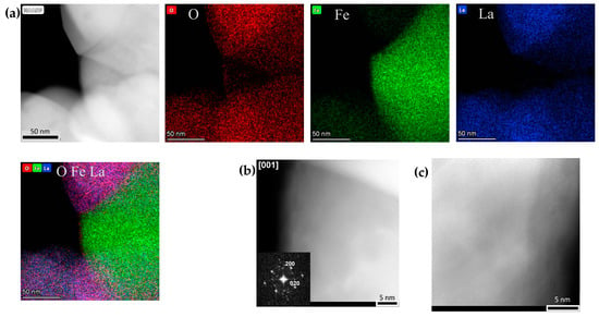
Figure 10.
(a) HAADF-STEM image and corresponding EDX compositional maps of the γ-Fe nanoparticles of the LaFe0.8Zn0.2O2.9/h-BN-derived nanocomposites with ~8% of γFe exsolved (Figure 9(a1,b1)). (b) [001] HAADF-STEM image of the γ-Fe nanoparticles, along with the Fourier transform. (c) HAADF-STEM image of highly twinned γ-Fe nanoparticle.
In the case of double substitution by Ca and Zn, the ACAR exsolution with h-BN will proceed as follows (Figure S2(a2,a3,b2,b3)):
La0.8Ca0.2Fe0.8Zn0.2O2.8 + BN + H2 → Fe + LaBO3 + Ca3La3(BO3)5 + La0.8+zCa0.2−zFe0.8−βZn0.2+βO3−γ + {ZnO} + N2 + H2O
At low reaction extents only γFe will be exsolved (Figure S2(b2)). In both cases, Zn-containing phases may precipitate at high reaction extents, presumably in oxide (ZnO) or borate forms, but in most of our samples they did not appear in the XRD patterns.
The lattice parameters of the cubic fcc cell of the exsolved γFe nanocrystals can be estimated from the room-temperature powder XRD patterns, in the range of 0.357–0.358 nm. These values correspond to those calculated for austenite solid solutions at room temperature when extrapolated to pure iron [39,40]. Since the γFe nanoparticles synthesized here at 650–750 °C are crystalline and are confined in oxide/borate matrices, they are not pyrophoric in air at room temperature. Moreover, they persist during heating/cooling cycles in a reducing atmosphere. However, a mild mechanical impact on the nanocomposites with high γFe content, by gently grinding in a mortar and pestle for 1–2 min, leads to the transformation of most of the γFe into αFe, and irreversibly so (Figure 9(a2,a3,b2,b3) and Figure S2(a3,a4,b3,b4), Table S6). This transition is, to some extent, analogous to transformations of retained austenite caused by mechanical deformation at low temperatures [41,42].
Note that for all the substituted ferrites investigated, the formation of Fe whiskers, which is considered undesirable during the described processes, was not observed.
2.4. Redox Behavior of the Exsolved Nanoparticles
The exsolved metal nanoparticles can be oxidized in air to iron oxides at elevated temperatures. The oxidation of metal nanoparticles is generally associated with a decrease in density and an increase in volume. As it was shown in [23], for CoNi exsolved, socketed nanoparticles, these volume changes lead to their migration from the initial sites under redox cycling conditions. In addition, redox cycling can cause the growth and coarsening of oxidized metal nanoparticles or their reintegration into perovskite matrices during oxidation [10,43,44]. For all the nanocomposites obtained herein, the embedded nanoparticles are also completely oxidized to αFe2O3 at 500 °C and above, in air. The γFe nanoparticles are oxidized first, and at lower temperatures of 200–300 °C, and their oxidation is accompanied by the transition of residual γFe into the α form (Figure 3(3,5), Table 1). However, the nanocomposites produced by ACAR-promoted exsolution exhibited peculiar behavior during redox cycling, or at least at the temperatures investigated. In these nanocomposites, the initial metal nanoparticles, after complete oxidation into αFe2O3 at 500 °C and above, can revert back to the metallic state by subsequent reduction in 10% H2/Ar at 650–750 °C and, remarkably, the metal γFe nanoparticles can be reinstated in the γ form through such a reduction of αFe2O3. Moreover, the γFe fractions may increase compared to the initial content, especially when Ca2Fe2O5 and its solid solutions have been used (Figure 3(1,2) and Figure 4(a3,a4,b3,b4)). To our knowledge, the formation of γFe nanoparticles from Fe oxides by hydrogen reduction at temperatures below 910 °C has not been reported previously. Like the formation of the initial γFe nanoparticles, this is presumably a compressive strain-driven behavior, which can be attributed to the preservation of the localization of all the nanoparticles, i.e., initially exsolved metallic-derived oxide and restored metallic oxide, within the voids, along with their strong binding to the void walls during the redox cycles. The γFe formation can, thus, be considered as a kind of indicator of the localization of nanoparticles inside the voids during these processes. Note that at the same time, there should also be free space inside the voids close to nanoparticles, sufficient to compensate for the metal/oxide volume difference, otherwise the matrix may be destroyed.
Using the above assumption on the nanoparticle redox behavior, the reversible transformation of γFe into αFe, and vice versa, through redox cycling at different oxidation temperatures can be realized (Figure 3, Table 1). The sample of the LaFeO3/h-BN based nanocomposite with ~30% of Fe exsolved was subjected to a preliminary oxidation (at 500 °C)/reduction cycle to maximize the γFe contribution (Figure 3(1,2), Table 1 (d123, d124)). To convert most of the Fe into the α form, the first stage involved oxidation at a low temperature of ~300 °C, where more chemically active γFe nanoparticles were partially oxidized/partially converted into αFe (Figure 3(3)), but the resulting oxides did not sufficiently sinter with the matrix. In the second stage, subsequent reduction at 700 °C yields αFe (Figure 3(4), see also Figure 1(a3,b4)). To regenerate γFe, the obtained αFe nanoparticles were first completely oxidized at 500 °C (Figure 3(5)), which provides sufficient sintering of the formed αFe2O3 particles and the matrix. Subsequent reduction, at the same temperature of 700 °C, regenerated the γFe nanoparticles (Figure 3(6)). According to the Mössbauer spectra, the Fe0 (metal)/Fe3+ (in matrix) ratio remained approximately the same during redox cycling (Table 1).
The TEM images of the reduced sample with ~11% of γFe and ~6% of αFe, obtained by the ACAR-promoted exsolution reaction of Ca0.7Y03(Fe0.9Zn0.1)O2.6 with h-BN, after an oxidation–reduction cycle demonstrate features similar to uncycled (only exsolved) nanocomposites: using EDX analysis, the Fe nanoparticles can be identified in some locations, embedded in the oxide matrix, along with some Y segregation (Figure S3).
2.5. ACAR-Promoted Exsolution of FeNix Alloys
It is well-established that the existence of a region of the γ form can be significantly extended to lower temperatures by creating an Fe alloy with certain elements, such as Ni [29]. The exsolution of NiFe alloy nanoparticles from Ni and Fe-containing perovskite-like oxides has also been reported [10,16,21], so the formation of FeNix alloys was expected during our process as well. Ni is less chemically active and more reducible compared to Fe, so Ni additions to La, and especially Ca, ferrites significantly decrease their stability in a reducing H2-containing atmosphere [27]. For this reason, the starting ferrites with low Ni content were used herein, to avoid decomposition. According to the XRD patterns shown in Figure 11a, the ACAR-promoted exsolution with h-BN from LaFe0.8Ni0.2O2.9, La0.8Ca0.2Fe0.8Ni0.2O2.8, and La0.5Ca0.5Fe0.9Ni0.1O2.7 can be written as follows:
LaFe0.8Ni0.2O2.9 + BN → FeNix + LaBO3 + LaFe0.8+βNi0.2−βO2.9+δ + N2
La0.8Ca0.2Fe0.8Ni0.2O2.8 + BN + H2 → FeNix + LaBO3 + Ca3La3(BO3)5 + La0.8+zCa0.2−zFe0.8+βNi0.2−βO2.8+δ + N2 + H2O
La0.5Ca0.5Fe0.9Ni0.1O2.7+ BN + H2 → FeNix + Ca3La3(BO3)5 + Ca3B2O6 + La0.5+zCa0.5−zFe0.9+βNi0.9−βO2.7+δ + N2 + H2O
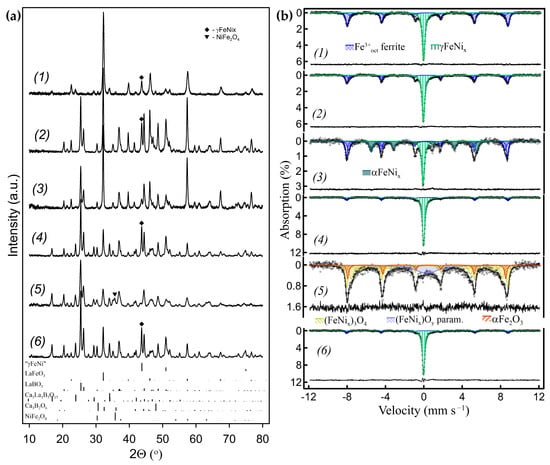
Figure 11.
(a) Powder XRD patterns and (b) corresponding RT Mössbauer spectra of the nanocomposites obtained by the ACAR-promoted exsolution from Ni-substituted ferrites: (1) La0.5Ca0.5Fe0.9Ni0.1O2.7/h-BN with ~41% of γFeNi exsolved; (2) from LaFe0.8Ni0.2O2.9/h-BN with ~53% of γFeNi exsolved; (3) sample (2) after grinding in a hand mortar (~25% γFeNi, ~29% αFeNi); (4) from La0.8Ca0.2Fe0.8Ni0.2O2.8/h-BN with ~82% of γFeNi exsolved; (5) sample (4) oxidized at 500 °C (~44%—NiFe2O4, ~16% αFe2O3, ~13% superparamagnetic phase); (6) after reduction of sample (5) (10% H2/Ar, 700 °C) (~83% γFeNi).
In these reactions, the resulting borates are the same as for the Ni-free ferrites described before (Figure 11(a1,a2,a4)). Note that while it is difficult to achieve exsolution levels of more than ~50% using metal Fe for the Ni-free ferrites due to cation mobility limitations, the reaction extent can be significantly higher for Ni-containing ferrites. As follows from the Mössbauer spectra shown in Figure 11(b1,b2,b4) and Table S7, Ni additions effectively stabilize the fcc structure of the exsolved nanoparticles. Their spectra are mainly comprised of two subspectra. The first, magnetically split with broad lines, correspond to Fe3+ cations in ferrites. It was fitted as a set of sextets, with δ~0.37 mm s−1 and Hhf~49–53 T. The second subspectrum, which was fitted as a paramagnetic singlet with δ~−0.07 mm s−1, corresponds to Fe in γFeNix alloys. According to the Fe–Ni phase diagram, at temperatures close to ambient, the αFe-based bcc phase αFeNix coexists with intermetallic compounds of Fe3Ni and FeNi fcc types in the Fe-rich region; although, the phase boundaries at these temperatures are difficult to determine [29]. The thermodynamically stable phases of FeNix alloys, viz. the Fe-rich bcc and the Ni-rich fcc alloys, are magnetically ordered at room temperature [45]. At elevated temperatures, there is a continuous solid solution of γFeNix with the eutectoid temperature of ~345–400 °C at ~50 at% of Ni. At ~10–20 at% of Ni, which matches the initial ferrite stoichiometry, the transition temperature is about ~650–700 °C. Since Ni is more reducible than Fe, the alloys at low degrees of exsolution will be enriched in Ni and their transition temperatures will be even lower. These temperatures are below the temperatures of 700–750 °C at which reactions (14, 15, and 16) were carried out. When cooled to room temperature, the XRD patterns show that all the exsolved FeNix nanoparticles retained their γ structure at room temperature (Figure 11(a1,a2,a4)). The Mössbauer subspectra corresponding to the FeNix nanoparticles consist of singlets with δ~−0.1 mm s−1 (Figure 11(b1,b2,b4)), evidencing that they are paramagnetic. It is consistent with their γ form, since paramagnetic behavior at room temperature has been reported for metastable γFeNix alloys with high Fe content [46,47]. The stabilization of the most exsolved γFeNix nanoparticles in γ form upon cooling, which can be explained by the strain developed due to their localization in voids, suggests that this is the main type of localization. Similar to γFe exsolved nanoparticles, a large part of γFeNix nanoparticles can be transformed into ferromagnetic αFeNix (Figure 11(b3)) by gently grinding in a mortar and pestle for 1–2 min. This treatment significantly reduced the FeNix reflections visually, in the XRD pattern of those samples (Figure 11(a3)). The mechanical stress-induced martensite γ to α transformation in Fe-rich Fe-Ni bulk alloys at room temperature has been previously reported in the literature [48,49].
The exsolved γFeNix nanoparticles can be completely oxidized at 500 °C and above, to the spinel solid solution Ni1±xFe2±xO4 (Figure 11(a5,b5)). Subsequent reduction in 10% H2/Ar atmosphere at 650–700 °C will restore the γFeNix metal nanoparticles (Figure 11(a6,b6)). It is noteworthy that the exsolution level for this sample was >80% (Table S7).
The TEM images of Ni-containing samples after the ACAR exsolution from La0.5Ca0.5Fe0.9Ni0.1O2.7 ferrite, with ~41% of Fe exsolved (Figure 11(a1,b1)), are shown in Figure 12a–d. Similar to other samples, the images show agglomerates of different contrast (Figure 12a–c). The embedded FeNix nanoparticles <30 nm in size, however, can be identified by EDX analysis, e.g., like in locations 2, 3, and 4 in Figure 12d. The alloy nanoparticles contained approximately about ~30 at% of Ni at this exsolution degree. Figure 12e shows the TEM images of this sample after gently grinding in a mortar with a pestle. There is not much difference compared to the unground ones, except for some rounded agglomerates of <25–30 nm located on the grain surfaces enriched in Fe and Ni, which can be identified as alloy nanoparticles (Figure 12e, loc. 2). Figure 12f shows the TEM images of the same unground sample after the oxidation (at 500 °C, air)/reduction (700 °C, 10% H2/Ar) cycle. Here again, it looks similar to the original sample with embedded FeNix nanoparticles, which were identified by EDX analysis (Figure 12f, loc. 2).
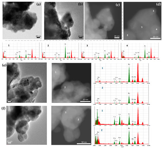
Figure 12.
(a,b) BF TEM, (c) HAADF-STEM images, and (d) EDX elemental analysis in the selected locations of the La0.5Ca0.5Fe0.9Ni0.1O2.7/h-BN nanocomposite with ~41% of γFeNi exsolved (Figure 11(1)) at different locations; (e) BF TEM and HAADF-STEM images and EDX elemental analysis in the selected locations after mortar grinding; (f) BF TEM and HAADF-STEM images and EDX elemental analysis of the same sample (a–d) in the selected locations of the sample after the oxidation/reduction cycle.
2.6. Separation of the Individual Nanoparticles
The reversible oxidation/reduction of metallic nanoparticles, while maintaining their localization within the in situ-created individual voids, is a remarkable feature of the nanocomposites produced by ACAR-promoted exsolution. It makes it possible to transform the initial metallic nanoparticles into various oxides, viz. Fe1−xO, Fe3O4, α/γFe2O3 etc., while preventing their agglomeration. The components of matrices, viz. the starting and resulting ferrites, resulting borates, etc., in turn, have very diverse chemical properties depending on their composition. In particular, unsubstituted, and certain substituted, Ca ferrites are susceptible to hydrolysis and dissolve in dilute mineral acids like HCl. Ca3B2O6 is also soluble in dilute acids. Since Fe3O4 (and γFe2O3) particles can dissolve reasonably slowly in dilute acidic aqueous solutions at RT, the crystallized and sintered Fe oxide nanoparticles, produced by the oxidation of the exsolved metal nanoparticles, can be separated from such oxide matrices by acid hydrolysis.
The TEM and SEM images of the nanoparticles separated from the Ca2Fe2O5/h-BN and Ca2FeAlO5/h-BN-derived nanocomposites (~30–35% of Fe exsolved) are shown in Figure 13 and Figure S5. Ca2Fe2−xAlxO5 ferrites of the brownmillerite type, including Ca2FeAlO5, obtained by the isovalent substitution of Fe3+ cations with Al3+, are also prone to hydrolysis as unsubstituted Ca2Fe2O5. They react with h-BN, similar to Ca2Fe2O5, according to the simplified reaction (17), where Al is mainly retained in the ferrite phase (Figure S4):
Ca2Fe2−xAlxO5 + BN + H2 → yFe + Ca3B2O6 + Ca2Fe2−x−yAlx+yO5 + N2 + H2O
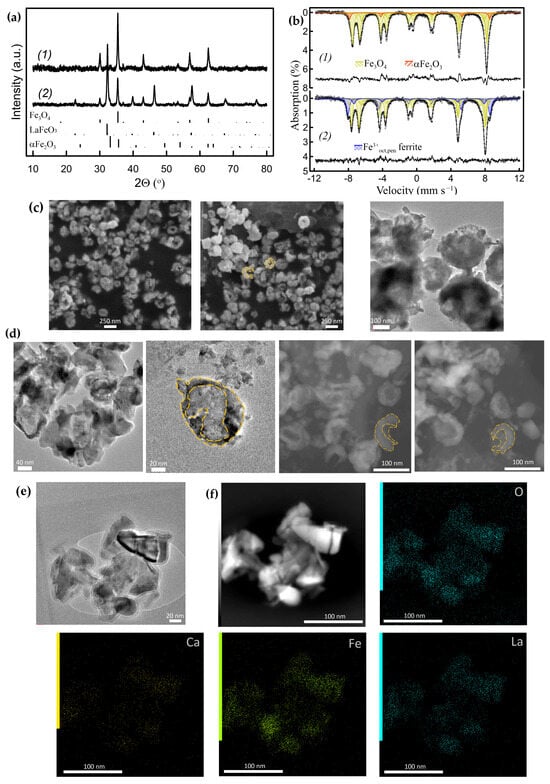
Figure 13.
Separated nanoparticles: (a) powder XRD patterns and (b) corresponding RT Mössbauer spectra of the nanoparticles obtained from the Ca2FeAlO5/h-BN-derived nanocomposite (a1,b1) and from the Ca0.8La0.2FeO2.6/h-BN derived nanocomposite (a2,b2). (c) SEM and BF TEM images of the Fe3O4 nanoparticles obtained from the Ca2Fe2O5/h-BN-derived nanocomposite. (d) BF TEM and HAADF-STEM images of the Fe3O4 nanoparticles obtained from sample (a1,b1) (dashed lines indicate the cup shape of the particles). (e) BF TEM and (f) HAADF-STEM images with corresponding EDX compositional map of the Fe3O4/La0.2+zCa0.8−zFeO3−γ nanoparticles obtained from sample (a2,b2).
The RT Mössbauer spectrum of the Ca2FeAlO5/h-BN-derived nanocomposite is shown in Figure S4(1). The subspectrum corresponding to Ca2Fe2−xAlxO5 is significantly broadened and unresolved due to the magnetic dilution by diamagnetic Al3+ cations. Therefore, the spectral contribution of exsolved Fe, which totaled ~35% (~5% γFe), was evaluated from the 78K Mössbauer spectra (Figure S4(2)).
Figure 13(a1,b1) shows the powder XRD patterns and Mössbauer spectra (Table S8) of the Fe3O4 nanoparticles separated from the Ca2FeAlO5/h-BN-derived nanocomposite. The transformation of metal Fe nanoparticles into Fe3O4 nanoparticles was carried out by their oxidation to αFe2O3 at 500 °C, followed by their reduction in 10% H2/Ar flow at 460–480 °C. The matrices were dissolved in 0.5–1.5% HCl aqueous solutions at RT. The Fe3O4 nanoparticles were magnetically separated and washed thoroughly with distilled water. It is worth noting that the leaching process of Fe3O4 can be carried out with high yields. This is facilitated by the fact that the particles were produced at relatively high temperatures at both stages of synthesis, viz. at oxidation of the metallic particles to Fe2O3 and at their subsequent reduction to Fe3O4 and were, therefore, crystallized and sintered well, which should reduce their solubility in diluted acids. Similar acid leaching in diluted aqueous HCl solutions has previously been successfully utilized to extract SrFe12O19-based nanoparticles, during high-temperature glass–ceramic synthesis [50].
The HAADF-STEM and SEM images of the separated nanoparticles obtained from the Ca2Fe2O5/h-BN and Ca2FeAlO5/h-BN-derived nanocomposites (~30–35% of Fe exsolved) reveal that most of them are cap-shaped (hemispherical) hollow nanostructures with sizes below ~200 nm and ~100 nm, respectively (Figure 13c,d and Figure S5). According to Figure 13 and Figure S5, the wall thickness of the oxide nanoparticles is of the order of a few nm, thus the wall thickness of the parent metallic nanoparticles should be of the same scale.
The separated nanoparticles provide insight into the shape and size of the parent metal nanoparticles within the matrices. These hollow cap-shaped oxide nanoparticles indicate that the exsolved metal nanoparticles are formed as an inner layer in individual voids generated in situ within the matrices. This particle shape can potentially provide free space sufficient to accommodate the volume increase during oxidation, if the hollow particles are not completely filled with other reaction products. At the same time, these shapes and locations appear to play an important role in creating the conditions necessary for the development of compressive strain in metal nanoparticles sufficient to stabilize γFe, which is somewhat analogous to the γFe formation in cylindrical pores [34].
The extracted nanoparticles were different when La-substituted Ca1−xLaxFeO2.5+δ ferrite was used as the starting material in the ACAR-promoted exsolution process. Figure 13e,f and Figure S6 show the TEM images of the oxide nanoparticles extracted from the nanocomposite obtained by the reaction of Ca0.8La0.2FeO2.6 with h-BN (~35% of Fe exsolved). Metallic Fe nanoparticles were converted into Fe3O4 nanoparticles in a similar manner as described above. According to reaction (14), the La content in the remaining perovskite oxide Ca0.8−zLa0.2+zFeO2.6+δ increases and, thus, its solubility in the dilute HCl aqueous solution decreases.
Using Mössbauer spectroscopy and XRD analyses, it was found that the extracted nanoparticles consisted mainly of spinel Fe3O4 and perovskite La0.2+zCa0.8−zFeO3−γ phases (Figure 13(a2,b2), Table S8). The TEM with EDX analysis revealed that the La0.2+zCa0.8−zFeO3-γ crystallites were segregated around Fe3O4 nanoparticles (Figure 13e,f and Figure S6). Most of them were almost completely covered by the resulting La–Ca ferrite, forming open shells. The size of the Fe3O4 nanoparticles was estimated to be smaller (<40–50 nm) than in the previous case. The composition and microstructure of the extracted nanoparticles reflect the relative arrangement of the metal/resulting ferrite phases in the parent nanocomposites. They show that the growth of exsolved metal nanoparticles in matrices is accompanied by the formation of shells, consisting of the resulting La-rich ferrites.
2.7. Variety of ACAR-Promoted Metal Exsolution Reactions
The new approach we have developed is not limited to the aforementioned ferrites and h-BN as starting compounds. The range of suitable compounds is wider and includes, but is not limited to, for example, Sr-containing ferrites and some other nitrides like Si3N4, etc. In particular, Figure S7 (Table S9) illustrates the ACAR-promoted exsolution of metal Fe nanoparticles from Sr2Fe2O5, with Si3N4 as a reducing agent, according to the simplified reaction (18):
Sr2Fe2O5 + 1/3Si3N4 + H2 → 2Fe + Sr2SiO4 + H2O + 2/3N2
Even CO gas can be utilized in reactions of this type with Ca and Sr ferrites, when it is added to 10%H2/Ar flow at ~650 °C, according to reaction (19):
(Sr,Ca)2Fe2O5 + 2CO + H2 → 2Fe + 2(Sr,Ca)CO3 + H2O
This reaction also leads to embedded metal α and γ Fe nanoparticles, as shown in Figure S8 [51].
The chemical activity of reducing reagents in ACAR processes is different, so that Si3N4 and CO are active with Ca and Sr-based ferrites, forming the corresponding silicates or carbonates, but are inactive towards La-based ferrites.
2.8. In Situ Reactions of Exsolved Nanoparticles
The exsolved metallic nanoparticles and their oxides can also be converted into other functional compounds, directly inside the matrices. For instance, embedded αFe2O3 nanoparticles obtained by the oxidation of exsolved metallic nanoparticles inside (La-based ferrite La0.8Ca0.2Fe0.8Zn0.2O2.8)/h-BN-derived nanocomposites (Figure 14(1)) can be converted into embedded χ-Fe5C2 (Hagg carbide) nanoparticles by the reaction with gaseous CO at 300–350 °C (Figure 14(2), Table S10), according to the scheme in Figure S9. This carbide is considered to be an active phase in Fischer–Tropsch synthesis [52,53,54]. Its Mössbauer subspectrum at RT consists of three broad Zeeman sextets, with δ of 0.18–0.25 mm s−1 and Hhf of 10–22 T, providing reliable identification [52]. The matrix, consisting of La ferrites and La borates, does not react with CO under the above conditions and remains unchanged. The α and, more significantly, γ Fe metallic nanoparticles can then be regenerated by the oxidation of carbide to αFe2O3 at 500 °C, followed by reduction to metal (Figure 14(3)), indicating that the metal/oxide/carbide nanoparticles retain their localization in the voids.
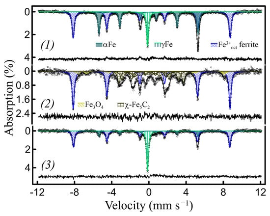
Figure 14.
RT Mössbauer spectra of the La0.8Ca0.2Fe0.8Zn0.2O2.8/h-BN-derived nanocomposites during redox cycling involving CO: (1) as prepared with ~51% of Fe exsolved (~14% γFe); (2) sample (1) after oxidation (air, 500 °C) following by the reaction with CO at 350 °C (~46% of Fe in χ-Fe5C2 carbide); (3) the same sample after the oxidation (air, 500 °C)–reduction (10%H2/Ar, 700 °C) cycle (~47% of metal Fe total, ~30% γFe).
3. Materials and Methods
3.1. Materials Preparation
The initial perovskite-like compounds used for the nanocomposite syntheses were prepared using a sol–gel routine from the respective nitrate precursors and citric acid as a complexing agent. All the chemicals were of reagent grade, from commercial sources (AO Reachem, Moscow, Russia). The aqueous solution of metal nitrates in the calculated amounts were mixed with concentrated citric acid solutions in the molar ratio of citric acid to metals at ~1.1. The pH of the solution was adjusted by a dilute ammonia solution to values of ~5–7. Several samples, mostly Sr-containing ones, were synthesized using ethylenediaminetetraacetic acid (EDTA) as a complexing agent. In this case, the respective nitrate solution was dropwise added to an EDTA solution in diluted aqueous ammonia and then the pH was adjusted to ~8. The water was evaporated from the mixed solution and the resulting viscous gels were heated to ~200 °C to yield porous brownish materials. The materials were ground and then calcined in air at 500 °C (heating rate was 5 °C/min) for 4 h. The samples were then calcined in air for 8–10 h at 700–900 °C. The substituted perovskites, usually containing Fe4+ and/or Fe(3+δ)+ cations in mixed oxidation states, were additionally treated in 10% H2/Ar gas flow at 600 °C for 1 h to reduce them to Fe3+.
The nanocomposites with exsolved particles were synthesized through the solid-state method. The required amounts of perovskite powders and h-BN (Plasmotherm, Moscow, Russia) or other reducing reagents were dry grounded in an agate mortar until homogeneous for 20–30 min. The mixture powders were placed into a silica reactor in alumina crucibles and heated in 10% H2/Ar gas flow of ~1–4 mL/min. The synthesis temperatures were ~650–700 °C and ~700–780 °C for the Ca- and La-based ferrites, respectively. For most of the samples used in this work, the exsolution reactions were carried out in a single step over ~10–16 h to reach completeness or a steady state. The experimental conditions for the synthesis of the nanocomposites are summarized in Table S1. The different extents of the exsolution reactions in this work were mainly predetermined by the ferrite/(h-BN, etc.) ratio, and the final amounts of exsolved Fe were quantified experimentally using Mössbauer spectroscopy.
3.2. Materials Characterization
The phase composition of the nanocomposites was characterized by X-ray powder diffraction (XRD), with a Huber G670 Image Plate Guinier diffractometer (CuKα1 radiation, curved Ge monochromator, image plate detector) (Huber Diffraktionstechnik GmbH & Co., Ltd., Rimsting, Germany).
The 57Fe Mössbauer spectra were recorded in terms of the transmission geometry on a commercial MS-1104EM spectrometer, using a 57Co(Rh) source (13.5 mCi), equipped with a custom liquid nitrogen bath cryostat (77–320 K) (ZAO, Kordon, Russia). The fitting procedure was performed with a special original least-squares fitting software developed at Lomonosov MSU. All the isomer shift values refer to αFe at room temperature (RT).
Scanning electron microscopy (SEM) analysis was performed using a Quattro S scanning electron microscope (LaB6 field emission cathode, Thermo Fisher Scientific, Bleiswijk, The Netherlands). Transmission electron microscopy (TEM) images and energy-dispersive X-ray (EDX) spectra were obtained with a JEOL 2100 F/Cs, operated at 200 kV and equipped with a JEOL system for EDX analysis (JEOL Ltd., Tokyo, Japan), and using an aberration-corrected Titan Themis Z transmission electron microscope at 200 kV (Thermo Fisher Scientific, The Netherlands), equipped with a Super-X system for EDX analysis. For the TEM studies, the powder samples of the nanocomposites were prepared by dispersing in ethanol or heptane without additional grounding to avoid sample destruction, and then depositing a few drops of the suspension on special grids.
4. Conclusions
The novel approach to metal exsolution using ABO3−γ (B = Fe, Ni, etc.) complex perovskite oxides of reducible transition metals has been developed to produce Fe-containing metal and metal oxide nanoparticles and nanocomposites. Our strategy is based on the additional auxiliary reactions of irreducible alkaline-earth and/or rare-earth A-site cations of the parent perovskite oxides with the constituents of reducing compounds resulting in the formation of complex oxides, which facilitate the exsolution of reducible transition metals from the B-sites of perovskites. The approach was applied mainly to Ca- and La-based unsubstituted and substituted ferrites as starting compounds and h-BN as a reducing compound. The metal nanoparticles exsolved by the described approach are largely localized within oxide matrices, in individual voids generated in situ. Moreover, the metal nanoparticles of Fe and FeNix alloys can be formed and stabilized in γ form, presumably due to induced compressive strain that develops in such locations.
The redox behavior of the exsolved nanoparticles was investigated. It was shown that they readily undergo redox cycling at moderate temperatures, where they maintain localization in the voids. The latter allows, under certain conditions, the regeneration of γFe and γFeNix from oxides during redox cycling. The nanoparticles can be chemically modified by reagents inside the matrices, while maintaining their localization.
The oxide matrices consist of unreacted initial perovskites and reaction products (borates, silicates, resulting perovskites, etc.) in various combinations and exhibit a wide variety of chemical and physical properties. They undergo significant transformation during the exsolution process, and their phase and chemical compositions depend on various factors, such as the composition of the initial ferrites and reducing reagents, the extent of reactions, and the reaction conditions, etc.
For certain Ca and Sr ferrite-based nanocomposites, a method has been developed for the separation oxide nanoparticles produced by the oxidation of the initially exsolved metal nanoparticles. The separated Fe3O4 nanoparticles (which can also be γFe2O3, etc.), obtained using Ca ferrites as starting materials, had a cup-shaped hollow shape. The separated nanoparticles obtained using La-substituted Ca ferrites were composite Fe3O4/(La-based resulting ferrite) layered particles. The separated nanoparticles provide insight into the shape, size, and relative arrangement of the phases of the parent metal nanoparticles within the matrices. This approach provides a new high-temperature templateless route for the synthesis of hollow and layered nanoparticles of Fe oxides and related compounds.
Our proposed strategy is applicable to a wide range of both perovskite-like oxides and reducing compounds. The developed approach provides greater flexibility in controlling the reaction extent, as well as the composition and properties of the resulting nanocomposites and nanoparticles. The approach can also be applied to the surface modification of perovskite oxide ceramics, since the starting perovskite compounds are considered stable under the reaction conditions. Our novel strategy is expected to be viable for the development of various new functional materials.
Supplementary Materials
The following supporting information can be downloaded at: https://www.mdpi.com/article/10.3390/inorganics12080223/s1, Figure S1. RT Mössbauer spectra of the Ca0.7Y0.3Fe0.9Zn0.1O2.6/h-BN-derived nanocomposites with 57% of Fe exsolved (~11% γFe); Figure S2. (a) Powders XRD patterns of the nanocomposites obtained by the ACAR exsolution from Zn-substituted LaFeO3: (a1) from LaFe0.8Zn0.2O2.9/h-BN with ~8% of γFe exsolved; (a2) from La0.8Ca0.2Fe0.8Zn0.2O2.8/h-BN with ~5% of γFe exsolved; (a3) from La0.8Ca0.2Fe0.8Zn0.2O2.8/h-BN with ~50% of Fe exsolved, where ~20%—γFe; (a4) sample (a3) after grinding in a mortar; (a5) sample (a3) oxidized at 500 °C (all Fe contributions are evaluated by Mössbauer spectroscopy) and (b) corresponding RT Mössbauer spectra: (b1) of sample (a1); (b2) of sample (a2); (b3) of sample (a3); (b4) of sample (a4); (b5,6) of sample (a5) at RT and 78K, respectively; Figure S3. (a) BF TEM image of the Ca0.7Y0.3Fe0.9Zn0.1O2.6/h-BN-derived nanocomposites (~18% of Fe) after the oxidation–reduction cycle; (b) HAADF-STEM images with corresponding EDX compositional maps of the sample in (a); Figure S4. The powder XRD pattern (a) and the corresponding RT Mossbauer spectrum (b) of the Ca2FeAlO5/h-BN-derived nanocomposite with ~35% of Fe exsolved (~5% of γFe); Figure S5. TEM images of the separated Fe3O4 nanoparticles obtained from the Ca2FeAlO5/h-BN-derived nanocomposites: (a) BF TEM; (b) HAADF-STEM images and EDX elemental analysis in the selected locations; Figure S6. TEM images of the separated Fe3O4/La1−yCayFeO2.5+ő nanoparticles obtained from the Ca0.8La0.2FeO2.6/h-BN-derived nanocomposite: (a) HAADF-STEM images with the corresponding EDX compositional map; (b) HAADF-STEM images and EDX elemental analysis in the selected locations; Figure S7. The powder XRD pattern (a) and the corresponding RT Mössbauer spectrum (b) of the Sr2Fe2O5/Si3N4-derived nanocomposite with ~60% of Fe exsolved (~9% of γFe); Figure S8. The RT Mossbauer spectrum of nanocomposites by ACAR-promoted by CO exsolution reactions: (1) from Sr2Fe2O5/CO with ~16% of Fe exsolved (~5% γFe); (2) from Ca2Fe2O5/CO with ~12% of Fe exsolved (~3% γFe); Figure S9. Scheme of transformations of the exsolved Fe nanoparticles during the redox cycle involving CO treatment; Table S1. Experimental conditions for the synthesis of nanocomposites by ACAR-promoted metal exsolution; Table S2. Hyperfine parameters of the RT Mössbauer spectra of the samples in Figure 4b; Table S3. Hyperfine parameters of the RT Mössbauer spectra of the Ca0.7Y0.3Fe0.9Zn0.1O2.6-derived nanocomposites in Figure 6a; Table S4. Hyperfine parameters of the RT Mössbauer spectra of the Ca0.7Y0.3Fe0.9Zn0.1O2.6-derived nanocomposites in Figure S1; Table S5. Hyperfine parameters of the RT Mössbauer spectra of the samples in Figure 9b; Table S6. Hyperfine parameters of the RT Mössbauer spectra of the samples in Figure S2b; Table S7. Hyperfine parameters of the RT Mössbauer spectra of the samples in Figure 11b; Table S8. Hyperfine parameters of the RT Mössbauer spectra of the samples in Figure 13d; Table S9. Hyperfine parameters of the RT Mössbauer spectra of the samples in Figure S7b; Table S10. Hyperfine parameters of the RT Mössbauer spectra of the samples in Figure 14.
Author Contributions
Conceptualization, D.F.; Methodology D.F.; Investigation, D.F., M.R., S.M. and D.P.; Formal analysis, D.F. and D.P.; Visualization, D.F.; Writing—original draft D.F.; Writing—review and editing, D.F. and D.P. All authors have read and agreed to the published version of the manuscript.
Funding
This work was partially supported by the State Assignments of Lomonosov Moscow State University (122030200324-1).
Data Availability Statement
The data will be made available from the corresponding author on reasonable request.
Acknowledgments
The authors are grateful to Artem Abakumov for help with the TEM characterization.
Conflicts of Interest
The authors declare that there are no conflicts of interest.
References
- Yadav, S.; Rani, N.; Saini, K. A review on transition metal oxides based nanocomposites, their synthesis techniques, different morphologies and potential applications. IOP Conf. Ser. Mater. Sci. Eng. 2022, 1225, 012004. [Google Scholar] [CrossRef]
- Ndolomingo, M.J.; Bingwa, N.; Meijboom, R. Review of supported metal nanoparticles: Synthesis methodologies, advantages and application as catalysts. J. Mater. Sci. 2020, 55, 6195–6241. [Google Scholar] [CrossRef]
- Gao, C.; Lyu, F.; Yin, Y. Encapsulated Metal Nanoparticles for Catalysis. Chem. Rev. 2021, 121, 834–881. [Google Scholar] [CrossRef]
- Hong, J.; Wang, B.; Xiao, G.; Wang, N.; Zhang, Y.; Khodakov, A.Y.; Li, J. Tuning the Metal–Support Interaction and Enhancing the Stability of Titania-Supported Cobalt Fischer–Tropsch Catalysts via Carbon Nitride Coating. ACS Catal. 2020, 10, 5554–5566. [Google Scholar] [CrossRef]
- Chen, A.; Su, Q.; Han, H.; Enriquez, E.; Jia, Q. Metal Oxide Nanocomposites: A Perspective from Strain, Defect, and Interface. Adv. Mater. 2019, 31, 1803241. [Google Scholar] [CrossRef]
- Přech, J.; Strossi Pedrolo, D.R.; Marcilio, N.R.; Gu, B.; Peregudova, A.S.; Mazur, M.; Ordomsky, V.V.; Valtchev, V.; Khodakov, A.Y. Core–Shell Metal Zeolite Composite Catalysts for In Situ Processing of Fischer–Tropsch Hydrocarbons to Gasoline Type Fuels. ACS Catal. 2020, 10, 2544–2555. [Google Scholar] [CrossRef]
- Yang, Q.; Liu, G.; Liu, Y. Perovskite-Type Oxides as the Catalyst Precursors for Preparing Supported Metallic Nanocatalysts: A Review. Ind. Eng. Chem. Res. 2018, 57, 1–17. [Google Scholar] [CrossRef]
- Rane, A.V.; Kanny, K.; Abitha, V.K.; Thomas, S. Chapter 5-Methods for Synthesis of Nanoparticles and Fabrication of Nanocomposites. In Synthesis of Inorganic Nanomaterials; Mohan Bhagyaraj, S., Oluwafemi, O.S., Kalarikkal, N., Thomas, S., Eds.; Woodhead Publishing: Sawston, UK, 2018; pp. 121–139. [Google Scholar]
- Kumar, A.; Dutta, S.; Kim, S.; Kwon, T.; Patil, S.S.; Kumari, N.; Jeevanandham, S.; Lee, I.S. Solid-State Reaction Synthesis of Nanoscale Materials: Strategies and Applications. Chem. Rev. 2022, 122, 12748–12863. [Google Scholar] [CrossRef]
- Kousi, K.; Tang, C.Y.; Metcalfe, I.S.; Neagu, D. Emergence and Future of Exsolved Materials. Small 2021, 17, 27. [Google Scholar] [CrossRef]
- Kim, J.H.; Kim, J.K.; Liu, J.; Curcio, A.; Jang, J.-S.; Kim, I.-D.; Ciucci, F.; Jung, W. Nanoparticle Ex-solution for Supported Catalysts: Materials Design, Mechanism and Future Perspectives. ACS Nano 2021, 15, 81–110. [Google Scholar] [CrossRef]
- Sun, Z.; Hao, C.; Toan, S.; Zhang, R.; Li, H.; Wu, Y.; Liu, H.; Sun, Z. Recent advances in exsolved perovskite oxide construction: Exsolution theory, modulation, challenges, and prospects. J. Mater. Chem. A 2023, 11, 17961–17976. [Google Scholar] [CrossRef]
- Neagu, D.; Irvine, J.T.S.; Wang, J.; Yildiz, B.; Opitz, A.K.; Fleig, J.; Wang, Y.; Liu, J.; Shen, L.; Ciucci, F.; et al. Roadmap on exsolution for energy applications. J. Phys. Energy 2023, 5, 031501. [Google Scholar] [CrossRef]
- Tilley, R.J.D. The ABX3 Perovskite Structure. In Perovskites; Tilley, R.J.D., Ed.; John Wiley & Sons, Ltd.: Chichester, UK, 2016; pp. 1–41. [Google Scholar]
- Peña, M.A.; Fierro, J.L.G. Chemical Structures and Performance of Perovskite Oxides. Chem. Rev. 2001, 101, 1981–2018. [Google Scholar] [CrossRef] [PubMed]
- Shah, S.; Xu, M.; Pan, X.; Gilliard-Abdulaziz, K.L. Exsolution of Embedded Ni–Fe–Co Nanoparticles: Implications for Dry Reforming of Methane. ACS Appl. Nano Mater. 2021, 4, 8626–8636. [Google Scholar] [CrossRef]
- Chen, H.; Yu, H.; Peng, F.; Yang, G.; Wang, H.; Yang, J.; Tang, Y. Autothermal reforming of ethanol for hydrogen production over perovskite LaNiO3. Chem. Eng. J. 2010, 160, 333–339. [Google Scholar] [CrossRef]
- Wang, J.; Woller, K.B.; Kumar, A.; Zhang, Z.; Zhou, H.; Waluyo, I.; Hunt, A.; LeBeau, J.M.; Yildiz, B. Ion irradiation to control size, composition and dispersion of metal nanoparticle exsolution. Energy Environ. Sci. 2023, 16, 5464–5478. [Google Scholar] [CrossRef]
- Santaya, M.; Jiménez, C.E.; Arce, M.D.; Carbonio, E.A.; Toscani, L.M.; Garcia-Diez, R.; Knop-Gericke, A.; Mogni, L.V.; Bär, M.; Troiani, H.E. Exsolution versus particle segregation on (Ni,Co)-doped and undoped SrTi0.3Fe0.7O3−δ perovskites: Differences and influence of the reduction path on the final system nanostructure. Int. J. Hydrogen Energy 2023, 48, 38842–38853. [Google Scholar] [CrossRef]
- Amaya-Duenas, D.M.; Chen, G.X.; Weidenkaff, A.; Sata, N.; Han, F.; Biswas, I.; Costa, R.; Friedrich, K.A. A-site deficient chromite with in situ Ni exsolution as a fuel electrode for solid oxide cells (SOCs). J. Mater. Chem. A 2021, 9, 5685–5701. [Google Scholar] [CrossRef]
- Santaya, M.; Jiménez, C.E.; Troiani, H.E.; Carbonio, E.A.; Arce, M.D.; Toscani, L.M.; Garcia-Diez, R.; Wilks, R.G.; Knop-Gericke, A.; Bär, M.; et al. Tracking the nanoparticle exsolution/reoxidation processes of Ni-doped SrTi0.3Fe0.7O3−δ electrodes for intermediate temperature symmetric solid oxide fuel cells. J. Mater. Chem. A 2022, 10, 15554–15568. [Google Scholar] [CrossRef]
- Oh, D.; Colombo, F.; Nodari, L.; Kim, J.H.; Kim, J.K.; Lee, S.; Kim, S.; Kim, S.; Lim, D.-K.; Seo, J.; et al. Rocking chair-like movement of ex-solved nanoparticles on the Ni-Co doped La0.6Ca0.4FeO3−δ oxygen carrier during chemical looping reforming coupled with CO2 splitting. Appl. Catal. B 2023, 332, 122745. [Google Scholar] [CrossRef]
- Neagu, D.; Papaioannou, E.I.; Ramli, W.K.W.; Miller, D.N.; Murdoch, B.J.; Ménard, H.; Umar, A.; Barlow, A.J.; Cumpson, P.J.; Irvine, J.T.S.; et al. Demonstration of chemistry at a point through restructuring and catalytic activation at anchored nanoparticles. Nat. Commun. 2017, 8, 1855. [Google Scholar] [CrossRef] [PubMed]
- Weber, M.L.; Wilhelm, M.; Jin, L.; Breuer, U.; Dittmann, R.; Waser, R.; Guillon, O.; Lenser, C.; Gunkel, F. Exsolution of Embedded Nanoparticles in Defect Engineered Perovskite Layers. ACS Nano 2021, 15, 4546–4560. [Google Scholar] [CrossRef] [PubMed]
- Wang, J.; Syed, K.; Ning, S.; Waluyo, I.; Hunt, A.; Crumlin, E.J.; Opitz, A.K.; Ross, C.A.; Bowman, W.J.; Yildiz, B. Exsolution Synthesis of Nanocomposite Perovskites with Tunable Electrical and Magnetic Properties. Adv. Funct. Mater. 2022, 32, 2108005. [Google Scholar] [CrossRef]
- Syed, K.; Wang, J.; Yildiz, B.; Bowman, W.J. Bulk and surface exsolution produces a variety of Fe-rich and Fe-depleted ellipsoidal nanostructures in La0.6Sr0.4FeO3 thin films. Nanoscale 2022, 14, 663–674. [Google Scholar] [CrossRef] [PubMed]
- Nakamura, T.; Petzow, G.; Gauckler, L.J. Stability of the perovskite phase LaBO3 (B = V, Cr, Mn, Fe, Co, Ni) in reducing atmosphere I. Experimental results. Mater. Res. Bull. 1979, 14, 649–659. [Google Scholar] [CrossRef]
- Dreyer, M.; Krebs, M.; Najafishirtari, S.; Rabe, A.; Friedel Ortega, K.; Behrens, M. The Effect of Co Incorporation on the CO Oxidation Activity of LaFe1−xCoxO3 Perovskites. Catalysts 2021, 11, 550. [Google Scholar] [CrossRef]
- Ohnuma, I.; Shimenouchi, S.; Omori, T.; Ishida, K.; Kainuma, R. Experimental determination and thermodynamic evaluation of low-temperature phase equilibria in the Fe–Ni binary system. Calphad 2019, 67, 101677. [Google Scholar] [CrossRef]
- Bundy, F.P. Pressure—Temperature Phase Diagram of Iron to 200 kbar, 900 °C. J. Appl. Phys. 2004, 36, 616–620. [Google Scholar] [CrossRef]
- Bhadeshia, H.; Honeycombe, R. (Eds.) Chapter 1-Iron and Its Interstitial Solutions. In Steels: Microstructure and Properties, 4th ed.; Butterworth-Heinemann: Oxford, UK, 2017; pp. 1–22. [Google Scholar]
- Shalimov, A.; Potzger, K.; Geiger, D.; Lichte, H.; Talut, G.; Misiuk, A.; Reuther, H.; Stromberg, F.; Zhou, S.; Baehtz, C.; et al. Fe nanoparticles embedded in MgO crystals. J. Appl. Phys. 2009, 105, 064906. [Google Scholar] [CrossRef]
- Yuan, C.L.; Hu, C.; Mei, Y.X.; Hong, A.J.; Yang, Y.; Xu, K.; Yu, T.; Luo, X.F. Strain-induced FCC Fe nanocrystals confined in Al2O3 matrix. J. Alloys Compd. 2017, 727, 1100–1104. [Google Scholar] [CrossRef]
- Yamada, Y.; Tanabe, K.; Nishida, N.; Kobayashi, Y. Iron films deposited on porous alumina substrates. Hyperfine Interact. 2016, 237, 9. [Google Scholar] [CrossRef]
- Fu, B.; Huebner, W.; Trubelja, M.F.; Stubican, V.S. (Y1−xCax)FeO3: A Potential Cathode Material for Solid Oxide Fuel Cells. ECS Proc. Vol. 1993, 1993, 276. [Google Scholar] [CrossRef]
- Grenier, J.-C.; Fournès, L.; Pouchard, M.; Hagenmuller, P.; Komornicki, S. Mössbauer resonance studies on the Ca2Fe2O5-LaFeO3 system. Mater. Res. Bull. 1982, 17, 55–61. [Google Scholar] [CrossRef]
- Vallet-Regí, M.; González-Calbet, J.; Alario-Franco, M.A.; Grenier, J.-C.; Hagenmuller, P. Structural intergrowth in the CaxLa1−xFeO3−x2 system (0 ≤ x ≤ 1): An electron microscopy study. J. Solid State Chem. 1984, 55, 251–261. [Google Scholar] [CrossRef]
- Price, P.M.; Browning, N.D.; Butt, D.P. Microdomain Formation, Oxidation, and Cation Ordering in LaCa2Fe3O8+y. J. Am. Ceram. Soc. 2015, 98, 2248–2254. [Google Scholar] [CrossRef][Green Version]
- Rammo, N.N.; Abdulah, O.G. A model for the prediction of lattice parameters of iron–carbon austenite and martensite. J. Alloys Compd. 2006, 420, 117–120. [Google Scholar] [CrossRef]
- Reed, R.P.; Schramm, R.E. Lattice Parameters of Martensite and Austenite in Fe–Ni Alloys. J. Appl. Phys. 2003, 40, 3453–3458. [Google Scholar] [CrossRef]
- Tavares, S.S.M.; Pardal, J.M.; da Silva, M.J.G.; Abreu, H.F.G.; da Silva, M.R. Deformation induced martensitic transformation in a 201 modified austenitic stainless steel. Mater. Charact. 2009, 60, 907–911. [Google Scholar] [CrossRef]
- Sohrabi, M.J.; Naghizadeh, M.; Mirzadeh, H. Deformation-induced martensite in austenitic stainless steels: A review. Arch. Civ. Mech. Eng. 2020, 20, 124. [Google Scholar] [CrossRef]
- Lai, K.-Y.; Manthiram, A. Evolution of Exsolved Nanoparticles on a Perovskite Oxide Surface during a Redox Process. Chem. Mater. 2018, 30, 2838–2847. [Google Scholar] [CrossRef]
- Weber, M.L.; Sohn, Y.J.; Dittmann, R.; Waser, R.; Menzler, N.H.; Guillon, O.; Lenser, C.; Nems, S.; Gunkel, F. Reversibility limitations of metal exsolution reactions in niobium and nickel co-doped strontium titanate. J. Mater. Chem. A 2023, 11, 17718–17727. [Google Scholar] [CrossRef]
- Xiong, W.; Zhang, H.; Vitos, L.; Selleby, M. Magnetic phase diagram of the Fe–Ni system. Acta Mater. 2011, 59, 521–530. [Google Scholar] [CrossRef]
- Cherdyntsev, V.V.; Pustov, L.Y.; Kaloshkin, S.D.; Tomilin, I.A.; Shelekhov, E.V.; Estrin, E.I.; Baldokhin, Y.V. Phase transformations in powder iron-nickel alloys produced by mechanical alloying. Phys. Met. Metallogr. 2009, 107, 466–477. [Google Scholar] [CrossRef]
- Kumar, S.; Roy, K.; Maity, K.; Sinha, T.P.; Banerjee, D.; Das, K.C.; Bhattacharya, R. Superparamagnetic Behavior of Fe–Ni Alloys at Low Ni Concentration. Phys. Status Solidi 1998, 167, 175–181. [Google Scholar] [CrossRef]
- Sato, H.; Nishiura, T.; Moritani, T.; Watanabe, Y. Atypical phase transformation behavior of Fe-33%Ni alloys induced by shot peening. Surf. Coat. Technol. 2023, 462, 129470. [Google Scholar] [CrossRef]
- Guimarães, J.R.C.; Rios, P.R. The mechanical-induced martensite transformation in Fe–Ni–C alloys. Acta Mater. 2015, 84, 436–442. [Google Scholar] [CrossRef]
- Trusov, L.A.; Sleptsova, A.E.; Duan, J.; Gorbachev, E.A.; Kozlyakova, E.S.; Anokhin, E.O.; Eliseev, A.A.; Karpov, M.A.; Vasiliev, A.V.; Brylev, O.A.; et al. Glass-Ceramic Synthesis of Cr-Substituted Strontium Hexaferrite Nanoparticles with Enhanced Coercivity. Nanomaterials 2021, 11, 924. [Google Scholar] [CrossRef] [PubMed]
- Filimonov, D.S.; Pokholok, K.V.; Rozova, M.G. Fe/perovskite nanocomposites as a result of partial decompositon of substituted strontium ferrites. In Proceedings of the 22th International Meeting Order, Disorder and Properties of Oxides, Rostov-on-Don, Russia, 4–9 September 2019; pp. 185–187. [Google Scholar]
- Gu, B.; Ordomsky, V.V.; Bahri, M.; Ersen, O.; Chernavskii, P.A.; Filimonov, D.; Khodakov, A.Y. Effects of the promotion with bismuth and lead on direct synthesis of light olefins from syngas over carbon nanotube supported iron catalysts. Appl. Catal. B 2018, 234, 153–166. [Google Scholar] [CrossRef]
- Chernavskii, P.A.; Kazantsev, R.V.; Pankina, G.V.; Pankratov, D.A.; Maksimov, S.V.; Eliseev, O.L. Unusual Effect of Support Carbonization on the Structure and Performance of Fe/MgAl2O4 Fischer–Tropsch Catalyst. Energy Technol. 2021, 9, 2000877. [Google Scholar] [CrossRef]
- Opeyemi Otun, K.; Yao, Y.; Liu, X.; Hildebrandt, D. Synthesis, structure, and performance of carbide phases in Fischer-Tropsch synthesis: A critical review. Fuel 2021, 296, 120689. [Google Scholar] [CrossRef]
Disclaimer/Publisher’s Note: The statements, opinions and data contained in all publications are solely those of the individual author(s) and contributor(s) and not of MDPI and/or the editor(s). MDPI and/or the editor(s) disclaim responsibility for any injury to people or property resulting from any ideas, methods, instructions or products referred to in the content. |
© 2024 by the authors. Licensee MDPI, Basel, Switzerland. This article is an open access article distributed under the terms and conditions of the Creative Commons Attribution (CC BY) license (https://creativecommons.org/licenses/by/4.0/).