Article

Fabrication of a Laminated Actuator with Excellent Linearity Using Ground Potassium Sodium Niobate-Based Ceramic Sheets

1
School of Mechanical & Intelligent Manufacturing, Jiujiang University, Jiujiang 332005, China
2
School of Materials Engineering, Jiangsu University, Zhenjiang 212013, China
*
Authors to whom correspondence should be addressed.
Inorganics 2024, 12(1), 18; https://doi.org/10.3390/inorganics12010018
Submission received: 31 October 2023 / Revised: 7 December 2023 / Accepted: 29 December 2023 / Published: 31 December 2023

Abstract

:
Linearity is an important factor that affects actuator accuracy. However, the high nonlinearity of KNN piezoelectric ceramics restricts their application in actuators. In this study, we used grinding stress to improve the linearity of ceramic chips, and used them to fabricate a laminated actuator. The ceramic sheets were ground to a thickness of 0.5 mm. During grinding, some areas of the ceramic changed from tetragonal to orthorhombic, owing to the grinding stress. The piezoelectric constant (d33) increased from 198 to 268 pC/N. Notably, the linearity of the ceramics improved. Seven pieces of ground ceramics were bound, to fabricate a laminated multilayer actuator with a total thickness of 3.5 mm. A DC voltage was applied to the actuator, and the displacement was measured. The displacement reached 0.73 μm under a low driving voltage of 200 V. A linear regression analysis of the displacement–voltage relationship was performed, obtaining the regression equation of the actuator. The linearity correlation coefficient was approximately 0.9903, implying that the actuator exhibits a high accuracy. The grinding stress improved the linearity, together with the piezoelectric properties of the ceramic chips, thus improving the actuator accuracy. This research will promote the application of KNN piezoelectric ceramics in actuators.

1. Introduction

Lead-based piezoelectric ceramic actuators, with their advantage of high precision, have been widely used in several precise positioning applications. However, owing to amended international environmental protection requirements, in actuators, lead-based ceramics are being replaced with lead-free piezoelectric ceramics. In the field of lead-free piezoelectric ceramics, the most extensively studied systems currently include sodium bismuth titanate (BNT)-based lead-free piezoelectric ceramics [1,2], barium ferrite (BT)-based lead-free piezoelectric ceramics [3,4], and potassium sodium niobate (KNN)-based lead-free piezoelectric ceramics. These systems are all perovskite-structured piezoelectric ceramics, each with their own strengths and weaknesses. Bismuth sodium titanate (BNT) is a ferroelectric material obtained by A-site substitution of the ABO3 perovskite structure. It was first synthesized by Sateskiilz et al., and is currently one of the most studied lead-free piezoelectric ceramic systems [5]. BNT has a low sintering temperature, is easy to prepare, has good ferroelectric and piezoelectric properties, and has significant anisotropy. However, when BNT is in the ferroelectric phase, it has a higher conductivity, leading to a larger residual polarization and a larger coercive field, which are not conducive to polarization. BaTiO3 (BT) has a perovskite structure of ABO3, with a stable electrical performance at room temperature, low loss, and a high electromechanical coupling coefficient. However, its low voltage coefficient (d33) and easily saturated hysteresis loop limit its application in energy storage and piezoelectric fields, to some extent. In order to improve the piezoelectric coefficient of BT and optimize its energy storage performance, researchers have conducted many studies in recent years, finally finding that the piezoelectric coefficient of BT-based piezoelectric ceramics can be significantly enhanced at MPB and PPB. In addition, via modifications, a relaxor ferroelectric phase can be constructed in BT ceramics. The polar nanoregions (PNRs) present in the relaxor ferroelectric phase can reduce the coercive field and thin the hysteresis loop of BT ceramics. A thin hysteresis loop ensures the applicability of BT ceramics in energy storage capacitors. In recent years, there have been many studies on the applications of barium ferrite (BT)-based lead-free piezoelectric ceramics in energy storage capacitors [6,7,8,9,10]. KNN piezoelectric ceramics have a relatively high Curie temperature, a good piezoelectric performance, and good practical value in piezoelectric driving, sensing, and transducers. Saito et al. [11] studied KNN-based piezoelectric ceramics in 2004. The piezoelectric constant of (K, Na, Li) (Nb, Ta, Sb) O3 textured ceramics with <001> orientation obtained via the template method can reach 416 pC/N, and exhibits a good temperature stability. The latest literature [12,13] indicated that by simultaneously changing the rhombic orthogonal and orthogonal tetragonal phase transition temperature points (TR-O and TO-T) to room temperature, a diffuse rhombic orthogonal tetragonal (R-O-T) multiphase is introduced, significantly improving the piezoelectric performance of KNN-based ceramics, which exhibited higher d33 values and an enhanced temperature stability. The d33 of the latest non-woven texture KNN-based ceramics can reach 490–650 pC/N, while d33 values of textured KNN-based ceramics and single crystals are 700 pC/N and 1050 pC/N. The piezoelectric properties of KNN-based ceramics have been significantly improved [11,14,15,16,17,18,19]; thus, research on their application is crucial.
Actuators are an important application of KNN piezoelectric ceramics; however, actuators made of KNN-based lead-free piezoelectric ceramics have not yet been systematically studied. This has resulted in the slow development of the applications of such ceramics. To achieve a large displacement and a low driving voltage, multilayer piezoelectric actuators are primarily fabricated by increasing the number of piezoelectric ceramic layers and reducing the thickness of each layer. At present, the two main types of multilayer actuators are low-temperature co-fired ceramics (LTCC) [20,21,22] and piezoelectric stack actuators (bonded laminates of ceramic slices) [23,24,25,26]. Piezoelectric stack actuators are more suitable than LTCC for applications requiring a large displacement and thrust; however, they have not been extensively studied. The thin ceramic sheets in multilayer actuators require a relatively low driving voltage. Therefore, the preparation of thin slices of high-performance piezoelectric ceramics is crucial for high-performance laminated actuators. Grinding, as a processing method for engineering ceramics, is widely used in engineering. Bifano’s research shows that the critical depth of the brittle plastic transition in ceramic grinding is inversely proportional to the cubic hardness. The hardness of engineering ceramics is generally above 10 GPa, while that of PZT ceramics is generally around 3.6 GPa. The hardness of KNN ceramics prepared by us has been tested, and was shown to be below 3.5 GPa. Therefore, it is easier to perform ductile domain grinding on piezoelectric ceramics than engineering ceramics. Grinding has greater development potential and application prospects for piezoelectric ceramic processing; however, there are few reports on piezoelectric ceramic grinding. Studies have shown that KNN ceramics are prone to undergo a transition from the tetragonal phase (T) to the orthogonal phase (O) under compressive stress, enhancing their piezoelectric properties [27,28]. During the grinding process, normal and tangential grinding stresses and the grinding heat act jointly on ceramics. Compared to applying an equal static pressure, the impact of grinding stress on the phase structure is more complex.
In this study, a piezoelectric stack actuator was prepared for further research, based on our previous work: 0.9625(K0.48Na0.52)(Nb0.6Sb0.4)O3-0.0375Bi0.5(Na0.82K0.18)0.5ZrO3 (0.9625KNNS-0.0375BNKZ) piezoelectric ceramic plates were fabricated, using a conventional solid-state reaction method. Subsequently, the ceramics were ground to a thickness of 0.5 mm. We studied the phase transformation in addition to the piezoelectric and mechanical properties of the ceramics during grinding. Finally, the stack actuator was fabricated by bonding the ground ceramic slices. The relationship between the displacement and the driving voltage was investigated. Furthermore, a regression equation was established, a fitting curve was obtained, and the linearity of the actuator was comprehensively analyzed.

2. Results and Discussion

2.1. Phase Observation and Analysis of Piezoelectric Ceramics

Figure 1a shows the X-ray diffraction (XRD) patterns of ceramics with thicknesses of 1.5 and 0.5 mm. The 1.5 mm-thick ceramic is unground ceramic; the 0.5 mm-thick slice was ground from 1.5 mm-thick ceramic. Figure 1b depicts the amplified XRD patterns with 2θ = 43.5–46.5°. Due to the similar lattice constants of orthogonal and tetragonal phases, it is common to encounter situations where two diffraction peaks overlap. In general, we can judge the crystal structure of the (002) peak near 45° in the XRD spectrum by comparing the relative intensities of the two peaks. When the intensity of the left peak is higher than that of the right peak, the material tends to be orthogonal phase; otherwise, it is tetragonal phase [29,30]. Figure 1b shows clearly that the left peak is less intense than the right peak of the 1.5 mm-thick ceramic before ground; therefore, it is tetragonal phase. In contrast, for the 0.5 mm-thick slice, after grinding, the intensity of the left peak is higher than that of the right one. Therefore, it can be concluded that grinding transformed the phase of the piezoelectric ceramic from tetragonal into orthorhombic.
Table 1 lists the lattice constants of the ceramics. The lattice constants changed slightly, owing to grinding. After grinding, a increased while c decreased, leading to a decrease in the c/a ratio, which indicates that the grinding resulted in lattice distortion. For orthogonal phases, a ≈ c, while for tetragonal phases, the relationship between lattice parameters is c > a. This result further corroborates the above-described analysis results. For the 1.5 mm-thick ceramic, c/a > 1. However, the c/a ratio of the 0.5 mm-thick ceramic decreased, indicating that the ceramic underwent a transformation from a tetragonal phase to an orthogonal phase after grinding. This further verifies the previous analysis.
The grinding process has an apparent impact on the phase structure, confirmed by the change in the shapes of the diffraction peaks and changes in the crystal axis ratio. Due to the addition of a cutting fluid during the grinding process, the grinding temperature is generally below 100 °C, which is much lower than the phase transition temperature of the ceramic. Therefore, it can be concluded that the main factor promoting the phase transition is the grinding stress. The phase transition caused by grinding stress in this study is consistent with some previous research findings. Wu et al. [30] examined the effect of stress on the phase transition of Pb(Zr1−xTix)O3. Kakimoto et al. [28] studied the Raman spectra of Li-doped KNN ceramics under different static pressures, and found that the orthorhombic phase is more likely to appear than the tetragonal phase, under the influence of pressure.

2.2. Surface Morphology Observations and Grinding Force Analysis

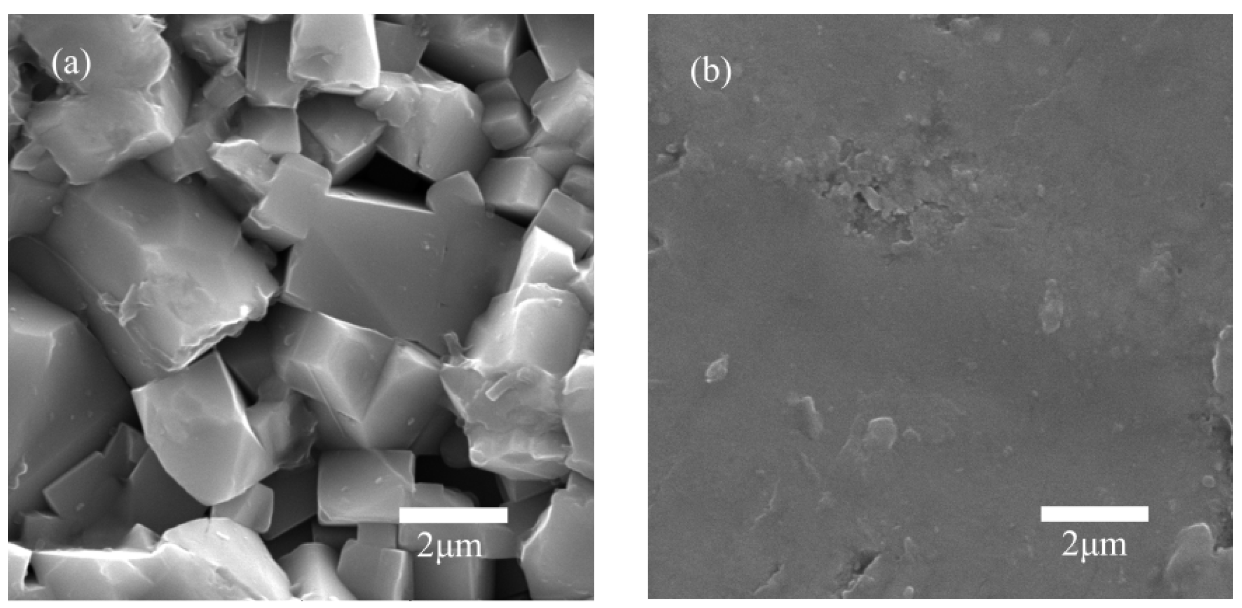
The surface morphology before and after grinding is shown in Figure 2a,b, respectively. There are apparent flat grinding marks on the surface of ceramics after grinding, and a few chippings. According to microscopic observations of the surface morphology and grinding debris [31], microplastic deformation occurs on the ceramic surface during grinding. The ground surface is under compressive stress, which improves the ceramics’ fracture strength and fracture toughness [32,33,34]. Two methods to remove ceramic surface materials are brittle fracture and plastic forming [35]. In general, the removal of materials by brittle fracture is accomplished by forming or extending, peeling, and breaking voids and cracks. The removal of plastic forming is similar to that of the cutting process in metal grinding, involving sliding, plowing, and chip formation; the materials are removed using a shear. In the grinding process, the grinding force is strongly associated with the shape, structure, hardness, particle size, abrasive, and grinding extent related to the grinding wheel. The grinding force magnitude depends on the combined effects of various factors. When the grinding force is less than the critical value P, intermediate cracks do not appear; the ceramic undergoes plastic deformation and the surface exhibits microplastic deformation [31]. The critical value P is calculated using Formula (1).
P = 54.5 ( α / η 2 γ 4 ) ( K C 4 / H 3 )
where α , η, and γ are constants (for a Vickers indenter, α = 2/π, η ≈ 1, γ ≈ 0.2); H is the material hardness; and KC is the fracture toughness.

2.3. Physical Properties of the Piezoelectric Ceramics

Table 2 lists the piezoelectric constants (d33) and dielectric constants (εr) of 1.5 and 0.5 mm-thick KNNS piezoelectric ceramics, respectively. The value of d33 increases after grinding. The transition temperature from the orthorhombic to tetragonal phase is crucial for enhancing the piezoelectric properties of KNN-based ceramics. A high piezoelectric constant was obtained in (Na0.53K0.47)0.942Li0.058NbO3 ceramics when the orthorhombic phase was increased by adjusting the cooling rate of sintering [28]. In this study, the increasing trend is attributed to the relatively easy polarization of the ceramic after being ground in the orthorhombic phase, which has twelve polarization directions. In contrast, the tetragonal phase has six polarization directions. Furthermore, Table 2 shows that the ceramic density is slightly increased, owing to extrusion on the surface during plastic deformation in the grinding process.

2.4. P−E Loops

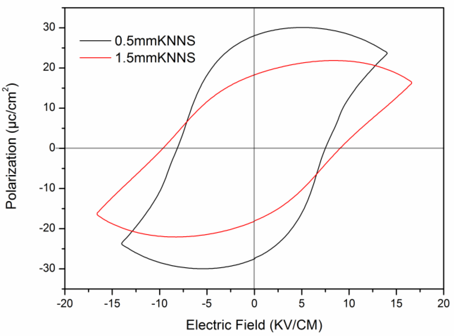
Figure 3 shows the polarization versus electric-field (PE) loops of 1.5 mm-thick unground KNNS-BNKZ and 0.5 mm-thick ground ceramics, respectively, at a frequency of 1 Hz at room temperature (18 °C). The ground 0.5 mm-thick ceramic exhibits a high remnant polarization (Pr) and a low coercive field (Ec), while the unground 1.5 mm-thick ceramic demonstrates a relatively low Pr and a high Ec. The ferroelectric phase plays an important role in hysteresis loops [36]. Li et al. [37] observed an increase in Pr and a decrease in Ec, which was linked to a phase change from tetragonal to rhombohedral in PZT ceramics. The rhombohedral phase has eight equivalent domain state directions, while the tetragonal phase only has six. According to the previous analysis, a tetragonal-to-orthorhombic phase transition occurs during the grinding process. The orthorhombic phase has twelve equivalent domain state directions, which is significantly more than those of the tetragonal phase. Therefore, the Pr value of the 0.5 mm-thick ground ceramic with the orthorhombic phase is higher, and its Ec is lower than that of the 1.5 mm-thick unground ceramic with the tetragonal phase. In addition, Pr decreases and Ec increases when the sample thickness is reduced to 0.15 mm. However, the thickness considered in our study was generally higher than 0.2 mm, which had a limited impact on the ceramics’ ferroelectric properties [37].

2.5. S−E Curves

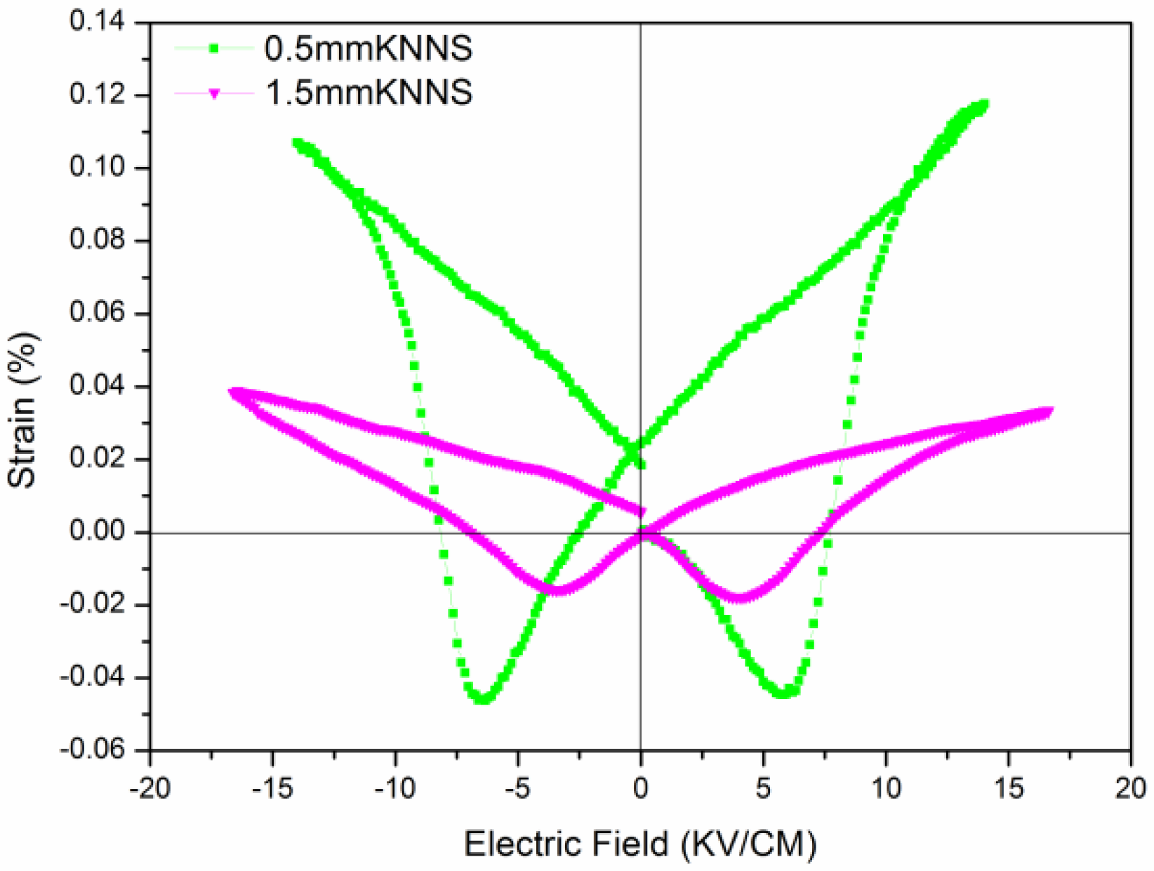
Figure 4 shows the strain versus electric-field (SE) curves of 1.5 mm-thick unground KNNS-BNKZ and 0.5 mm-thick ground ceramics, respectively. The strain of the ground ceramic is greater than that of the unground one under the same electric field, because d33 increases after grinding. In particular, the ground piezoelectric ceramic demonstrates excellent linearity. When the electric field is 10–15 kV/cm, the rising and falling voltage curves almost coincide, implying that the hysteresis is considerably smaller. The different types of strain hysteresis and nonlinearity are related to the electric fields required for domain switching. Yalin Qin [38] studied (K0.50Na0.50)l−xLix(Nb0.80Ta0.20)O3, and found that the hysteresis for the orthorhombic phase is significantly smaller than those for the tetragonal and orthorhombic–tetragonal phases at an electric field above 20 kV/cm. The c/a ratio of the tetragonal phase is larger than that of the orthorhombic phase, thereby inducing a higher stress and resulting in highly clamped conditions for domain wall reversal [39,40]. The strain of piezoelectric ceramics is attributed to the extrinsic domain wall switching and intrinsic piezoelectric effect. The former is caused by domain switching, which mainly contributes to strain and causes hysteresis. However, when the electric field exceeds a certain degree, the intrinsic piezoelectric effect related to lattice distortion becomes the main contributor, and the resultant hysteresis is considerably smaller. In our study, before grinding, the piezoelectric ceramics were composed of the tetragonal phase; thus, a high electric field was required for domain switching. After grinding, the ceramic was composed of the orthorhombic phase; consequently, the domain switching was activated by a relatively low electric field. Moreover, the PE loops in Figure 3 show that the maximum polarization electric field of the ground ceramics is lower than 15 kV/cm, while that of the unground ceramics is higher than 15 kV/cm, which may be the reason for the small hysteresis in a 10–15 kV/cm electric field. In high-precision actuator applications, by controlling the voltage, the actuator can be used in this voltage range with considerably small hysteresis. Therefore, the piezoelectric performance and the linearity are improved through grinding, and hysteresis decreases. This significantly improves the accuracy of the actuator.

2.6. Actuator Manufacture, Displacement Test, and Linear Regression

2.6.1. Manufacture of the Actuator

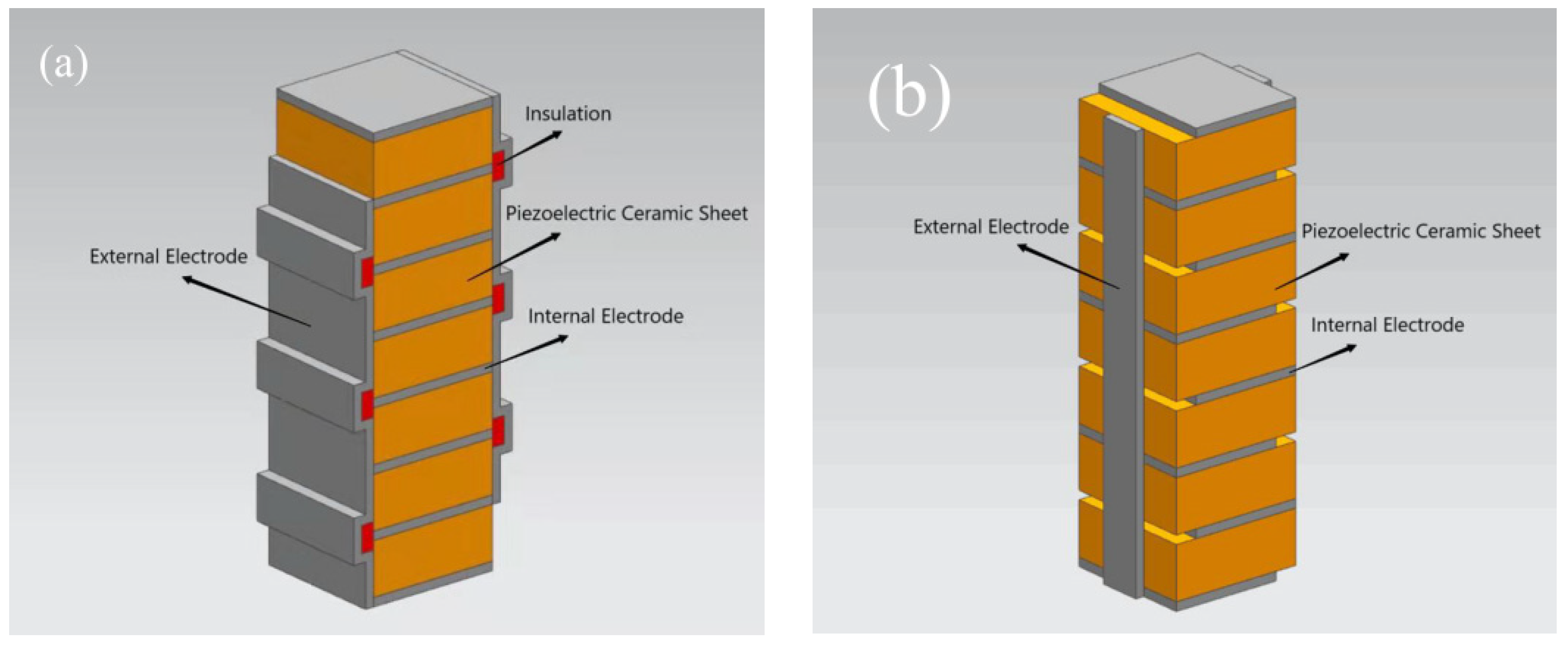
To reduce the voltage and increase the displacement of the actuator, fabrication with monolithic multilayer ceramic slices is frequently performed [41,42,43]. At present, LTCC and piezoelectric stacks are the two main types of actuators [44]. LTCC generally require a ceramic sintering temperature of approximately 900 °C [45,46]. However, the firing temperature of KNN ceramics is typically higher than 1100 °C. Therefore, LTCC are not suitable for KNN-based ceramics. As an alternative, we used the KNN slices that were ground to a 0.5 mm thickness for bonding and stacking. This is more suitable for a large displacement and thrust. The conventional method to avoid short circuiting of the electrodes in piezoelectric stack actuators involves leaving a certain margin at the edge of the ceramic slices when coating with silver, as shown in Figure 5b. However, this generates uneven stress on the ceramic sheet when the actuator is in use. Consequently, the ceramic sheet cracks, affecting the service life of the actuator. In this study, the surfaces of the ceramic sheets were uniformly coated with silver, without leaving any gaps, ensuring a uniform strain and stress on the ceramic sheets under a voltage. At the same time, insulation layers were coated on the sides of the actuator to avoid short circuits, as shown in Figure 5a.

2.6.2. Linear Regression Analysis of the Displacement–Voltage Relationship of the Actuator

The test platform consists of a combined digital display micrometer and sensor (Figure 6). A DC electric field was applied to the actuator, and the displacement value was recorded every 10 V in the range of 10–200 V. At 200 V, the maximum displacement was approximately 0.73 µm.
The theoretical formula of stack actuator displacement is shown in Formula (2), where ΔL is the total displacement of the actuator; N is the number of laminated ceramic slices; d33 is the piezoelectric constant of the ceramic sheet; and E is the applied electric field. According to this formula, when the piezoelectric constant and electric field remain the same, the total displacement is directly proportional to the number of ceramic pieces (N). In this study, only seven ceramic pieces, with a total thickness of 3.5 mm, were used. A greater displacement could be obtained by increasing the number of ceramic pieces.
Δ L = N × d 33 × E
The measured displacement and voltage data were analyzed using the least-squares method, and fitted using linear regression in the relevant software. The fitting line, regression equation, and coefficient of determination (R2) of the actuator within this voltage range were obtained. The regression equation is y = 0.0038x − 0.0757. The fitting curve has a value of R2 = 0.9903, as shown in Figure 7. It is generally believed that different types of strain nonlinearity are related to the electric field strength required for domain flipping. The electrical rotation of tetragonal phase components requires a higher electric field, while orthogonal phase components require a relatively lower electric field strength to cause domain rotation. Similar phenomena have also been reported in lead-containing perovskite systems [32,33]; therefore, the actuator in our research shows excellent linearity and high accuracy.

3. Materials and Methods

A solid-state reaction method was used to prepare 0.9625KNNS-0.0375BNKZ ceramic powders, which were then pressed into 1.5 mm-thick disks with a diameter of 15 mm, and sintered at 1140 °C. Subsequently, the piezoelectric ceramic disks were ground to thicknesses of 0.5 mm. A BLOHM Orbit 36 CNC precision flat forming grinder with a minimum resolution of 0.001 mm was used in this experiment. A water-based grinding fluid with a concentration of 3.8% and a flow rate of 80 L/min was used for cooling and lubrication. The forward grinding method was adopted. Firstly, the ceramic pieces were bound to a long glass plate using glue, and the glass plate was fixed onto the grinding machine workbench, through positioning blocks. The grinding process was carried out in three steps. The first step was to grind the ceramic pieces to 1 mm thickness with a 400 grit grinding wheel. The feed speed of the workbench was set to 200 mm/s. The grinding wheel speed was set to 50 m/s. A 0.2 mm cutting depth was used each time. The second step was to grind the ceramic pieces to 0.6 mm thickness with a 600 grit grinding wheel. The feed speed of the workbench was set to 100 mm/s and the grinding wheel speed was set to 40 m/s, with a cutting depth of 0.1 mm each time. The third step was to grind the ceramic pieces to 0.5 mm thickness using an 800 grit grinding wheel. The feed speed of the workbench was set to 50 mm/s and the grinding wheel speed was set to 30 m/s, with a cutting depth of 0.05 mm each time. After the grinding was complete, the glass plate was soaked in double-alkali water and detergent, to remove the ceramic pieces. Finally, the piezoelectric ceramic pieces were placed in boiling water and then rinsed with warm water and placed in an 80 degree oven for 24 h of annealing treatment.
The density of the samples was measured via the Archimedes method. The phase compositions of the ceramic samples were analyzed using X-ray diffraction (XRD, D8 ADVANCE, Bruker, Karlsruhe, Germany) at a scanning rate of 5°/min over the scanning range of 10–60° with a step size of 0.02°. The microstructures of the samples were identified using scanning electron microscopy (SEM, VEGA II LSU, TESCAN, Brno, Czech Republic). After the ceramic slices were cleaned using ultrasonic vibration, they were dried and painted with silver on both sides as electrodes, and fired at 650 °C for 15 min. Subsequently, poling was conducted in silicon oil at 80–100 °C under a DC field of 3 kV/mm for 20 min. Other electrical measurements were performed 24 h after poling. The piezoelectric constant (d33) was evaluated using a quasi-static instrument (ZJ-3A, JKZC Co., Ltd., Beijing, China). The samples’ dielectric performance was measured using a digital bridge tester (YY2814). A ferroelectric tester was used to obtain the PE (polarization versus electric field) loops and S–E curves, with a maximum field strength of 3 kV/mm. The displacement data were tested using a combination of a digital inductive micrometer with a precision of 0.01 µm (DGS-6C, ZHONGYUAN MEASURING, Sanmenxia, China) and an inductance sensor (DGC-8ZG/D, ZHONGYUAN MEASURING, China) at room temperature (18 °C). A linear regression analysis was carried out using Microsoft Excel(Microsoft, Redmond, WA, USA).
The ceramic slices were bonded and laminated by mechanical series and electrode parallel connections. The ceramic slices were laminated with a conductive adhesive, insulated on the corresponding side, and sealed with an epoxy resin 24 h after fixation. One end of the piezoelectric ceramic actuator was fixed to a special clamp using glue, and the other end was in a free state. A DC power supply with a voltage resolution lower than 10 V was used as the driving power; the displacement of the actuator was measured using a digital display micrometer. The entire test was conducted on a shock absorption platform. The starting voltage was 0 V, and the corresponding displacement was recorded at intervals of 10 V, until the voltage was 200 V. The average values of the measurements were considered, and the least-squares method was used to analyze the displacement versus voltage. The regression equation for the relationship between displacement and voltage was obtained, and the fitting curve was plotted. Finally, the linear characteristics of the actuator were analyzed.

4. Conclusions

KNN-based piezoelectric ceramics were prepared using a solid-state reaction method. The piezoelectric constant of the KNN piezoelectric ceramic was only 198 PC/N, but its piezoelectric properties and linearity were improved after grinding. During the grinding process, some areas of the ceramic changed from tetragonal to orthorhombic, under stress. The piezoelectric constant (d33) was improved to 268 PC/N. The value of Pr increased, whereas Ec decreased. The linearity of the displacement–voltage relationship improved. In our experiment, homemade piezoelectric ceramics with a low piezoelectric constant were used as raw materials for grinding, and an actuator with a thickness of 3.5 mm was fabricated. When the voltage was only 200 V, the displacement was 0.73 μm. More importantly, the correlation coefficient reached values of up to 0.9903, meeting the requirements of high-precision actuators. This will provide a new way for KNN piezoelectric ceramics to be used in actuators.

Author Contributions

Conceptualization, Y.Z.; investigation, F.L. and D.Z.; writing, Y.Z.; Resources, Y.Z.; Supervision, C.C.; Validation, F.L.; review and editing, Y.Z., C.C., Q.H., F.L. and D.Z. All authors have read and agreed to the published version of the manuscript.

Funding

This research was funded by Jiangxi Provincial Natural Science Foundation, No.20212BAB204047; Science and Technology Project of Jiangxi Provincial Department of Education, No. GJJ201812; and, the National Natural Science Foundation of China, No. 52175464 and No. 82360704.

Data Availability Statement

The data presented in this study are available on request from the corresponding author.

Acknowledgments

The authors acknowledge Xiaoling Peng’s support for our research team.

Conflicts of Interest

The authors declare no conflict of interest.

References

  1. Kang, W.S.; Koh, J.H. (1−x)Bi0.5Na0.5TiO3-xBaTiO3 lead-free piezoelectric ceramics for energy-harvesting applications. J. Eur. Ceram. Soc. 2015, 35, 2057–2064. [Google Scholar] [CrossRef]
  2. Mayamae, J.; Sukkha, U.; Niemchareon, S.; Muanghlua, R.; Vittayakorn, N. Ferroelectric and Piezoelectric Properties of the Lead Free 0.9BaTiO3-(0.1−x)Bi0.5Na0.5TiO3-xBi(Mg0.5Ti0.5)O3 Solid Solution. Ferroelectrics 2016, 490, 23–35. [Google Scholar] [CrossRef]
  3. Maiwa, H. Dielectric and Electromechanical Properties of BatiO3 Ceramics Prepared by HotIsostatic Pressing. Ferroelectrics 2014, 463, 15–24. [Google Scholar] [CrossRef]
  4. Fu, F.; Zhai, J.; Xu, Z.; Shen, B.; Yao, X. Grain growth kinetics of textured- Batioceramics. Bull. Mater. Sci. 2014, 37, 779–787. [Google Scholar] [CrossRef]
  5. Kimura, M.; Minamikawa, T.; Ando, A.; Sakabe, Y. Temperature characteristics of (ba1-xsrx)2nanb5o15 ceramics. J. Appl. Phys. 1997, 36, 6051–6054. [Google Scholar] [CrossRef]
  6. Kumar, N.; Ionin, A.; Ansell, T.; Kwon, S.; Hackenberger, W.; Cann, D. Multilayer ceramic capacitors based on relaxor BaTiO3-Bi(Zn1/2Ti1/2)O3 for temperature stable and high energy density capacitor applications. Appl. Phys. Lett. 2015, 106, 549. [Google Scholar] [CrossRef]
  7. Kumar, N.; Cann, D.P. Resistivity Enhancement and Transport Mechanisms in (1x)BaTiO3-xBi(Zn1/2Ti1/2)O3 and (1x)SrTiO3-xBi(Zn1/2Ti1/2)O3. J. Am. Ceram. Soc. 2015, 98, 2548–2555. [Google Scholar] [CrossRef]
  8. Huang, S.; Kim, T.; Hou, D.; Cann, D.; Jones, J.L.; Jiang, X. Flexoelectric characterization of BaTiO3-0.08Bi(Zn1/2Ti1/2)O3. Appl. Phys. Lett. 2017, 110, 1–4. [Google Scholar] [CrossRef]
  9. Hou, D.; Usher, T.M.; Zhou, H.; Raengthon, N.; Triamnak, N.; Cann, D.P.; Forrester, J.S.; Jones, J.L. Temperature-induced local and average structural changes in BaTiO3xBi(Zn1/2Ti1/2)O3 solid solutions: The origin of high temperature dielectric permittivity. J. Appl. Phys. 2017, 122, 064103. [Google Scholar] [CrossRef]
  10. Yu, L.; Deng, H.; Zhou, W.; Yang, P.; Chu, J. Structural characteristics and optical properties of lead-free Bi(Zn1/2Ti1/2)O3-BaTiO3 ceramics. Ceram. Int. 2017, 43, 6175–6179. [Google Scholar] [CrossRef]
  11. Saito, Y.; Takao, H.; Tani, T.; Nonoyama, T.; Takatori, K.; Homma, T.; Nagaya, T.; Nakamura, M. Lead-Free Piezoceramics. Nature 2004, 432, 84–87. [Google Scholar] [CrossRef] [PubMed]
  12. Liu, D.; Zhang, X.; Su, W.; Wang, X.; Yao, W.; Zhou, C.; Zhang, J. Outstanding piezoelectric properties, phase transitions and domain configurations of 0.963(K0.48Na0.52)(Nb0.955Sb0.045)O3−0.037(Bi0.50Na0.50)HfO3 ceramics. J. Alloys Compd. 2019, 779, 800–804. [Google Scholar] [CrossRef]
  13. Jiang, M.; Zhang, J.; Rao, G.; Li, D.; Randall, C.A.; Li, T.; Peng, B.; Li, L.; Gu, Z.; Liu, X.; et al. Ultrahigh piezoelectric coefficient of a lead -free K0.5Na0.5NbO3-based single crystal fabricated by a simple seed- free solid state growth method. J. Mater. Chem. C 2019, 7, 14845–14854. [Google Scholar] [CrossRef]
  14. Shrout, T.R.; Zhang, S.J. Lead-free piezoelectric ceramics: Alternatives for PZT? J. Electroceramics 2007, 19, 113–126. [Google Scholar] [CrossRef]
  15. Wu, J.; Xiao, D.; Zhu, J. Potassium-sodium niobate lead-free piezoelectric materials: Past, present, and future of phase boundaries. Chem. Rev. 2015, 115, 2559–2595. [Google Scholar] [CrossRef] [PubMed]
  16. Malič, B.; Koruza, J.; Hreščak, J.; Bernard, J.; Wang, K.; Fisher, J.G.; Benčan, A. Sintering of Lead-Free Piezoelectric Sodium Potassium Niobate Ceramics. Materials 2015, 8, 8117–8146. [Google Scholar] [CrossRef] [PubMed]
  17. Jiang, L.; Tan, Z.; Xing, J.; Wu, J.; Chen, Q.; Zhang, W.; Xiao, D.; Zhu, J. New potassium–sodium niobate ternary system with large piezoelectric coefficient and high Curie temperature. J. Mater. Sci. Mater. Electron. 2016, 27, 9812–9820. [Google Scholar] [CrossRef]
  18. Kong, Z.; Bai, W.; Zheng, P.; Zhang, J.; Wen, F.; Chen, D.; Shen, B.; Zhai, J. Enhanced electromechanical properties of CaZrO3-modified (K0.5Na0.5)NbO3-based lead-free ceramics. Ceram. Int. 2017, 43, 7237–7242. [Google Scholar] [CrossRef]
  19. Fang, X.; Jian, C.; Lu, Y.; Zhang, Q.; Qi, Z.; Zhou, T.; He, Y. Exploration on the origin of enhanced piezoelectric properties in transition-metal ion doped KNN based lead-free ceramics. Ceram. Int. 2018, 44, 16745–16750. [Google Scholar]
  20. Gongora-Rubio, M.R.; Espinoza-Vallejos, P.; Sola-Laguna, L.; Santiago-Aviles, J.J. Overview of low temperature co-fired ceramics tape technology for meso-system technology (MsST). Sens. Actuators 2001, A89, 222–241. [Google Scholar] [CrossRef]
  21. Park, H.Y.; Seo, I.T.; Choi, J.H.; Nahm, S.; Lee, H.G. Low-Temperature Sintering and Piezoelectric Properties of (Na0.5K0.5)NbO3 Lead-Free Piezoelectric Ceramics. J. Am. Ceram. Soc. 2010, 93, 36–39. [Google Scholar] [CrossRef]
  22. Liu, J.; Jia, P.; Zhang, H.; Tian, X.; Liang, H.; Hong, Y.; Liang, T.; Liu, W.; Xiong, J. Fiber-optic Fabry-Perot pressure sensor based on low-temperature co-fired ceramic technology for high-temperature applications. Appl. Opt. 2018, 57, 4211. [Google Scholar] [CrossRef] [PubMed]
  23. Qu, Z.Q. An efficient modelling method for laminated composite plates with piezoelectric sensors and actuators. Smart Mater. Struct. 2001, 10, 807. [Google Scholar] [CrossRef]
  24. Lin, J.C.; Nien, M.H. Adaptive modeling and shape control of laminated plates using piezoelectric actuators. J. Mater. Process. Technol. 2007, 189, 231–236. [Google Scholar] [CrossRef]
  25. Talebitooti, R.; Daneshjoo, K.; Jafari, S.A.M. Optimal control of laminated plate integrated with piezoelectric sensor and actuator considering TSDT and mesh free method. Eur. J. Mech.—A/Solids 2016, 55, 199–211. [Google Scholar] [CrossRef]
  26. Guo, Y.; Zhu, Y. Modeling and Analysis on Hysteresis Nonlinear Characteristics of the Piezoelectric Stack Actuators. Piezoelectrics Acoustooptics 2017, 39, 520–524. [Google Scholar]
  27. Kakimoto, K.I.; Sumi, T.; Kagomiya, I. Pressure-dependent raman scattering spectrum of piezoelectric (Li,Na,K)NbO3 lead-free ceramics. Jpn. J. Appl. Phys. 2010, 49, 09MD10. [Google Scholar] [CrossRef]
  28. Zhao, Y.; Zhao, Y.; Zhang, X.; Huang, R.; Liu, R.; Zhou, H. The effect of sintering and poling processing on the phase structure of Li0.058(Na0.51K0.49)0.942NbO3 lead-free ceramics. Scr. Mater. 2012, 66, 97–100. [Google Scholar] [CrossRef]
  29. Zhou, J.J.; Li, J.F.; Zhang, X.W. Orthorhombic to tetragonal phase transition due to stress release in (Li,Ta)-doped(K,Na)NbO3 lead-free piezoceramics. J. Eur. Ceram. Soc. 2012, 32, 267–270. [Google Scholar] [CrossRef]
  30. Wu, C.; Duan, W.; Zhang, X.W.; Liu, Z. Effects of hydrostatic pressure on Pb(Zr1−xTix)O3 near the morphotropic phase boundary. J. Appl. Phys. 2010, 108, 124102. [Google Scholar] [CrossRef]
  31. Malkin, S.; Hwang, T.W. Grinding Mechanisms for Ceramics. CIRP Ann.—Manuf. Technol. 1996, 45, 569–580. [Google Scholar] [CrossRef]
  32. Denkena, B.; Busemann, S.; Gottwik, L.; Grove, T.; Wippermann, A. Material Removal Mechanisms in Grinding of Mixed Oxide Ceramics. Procedia Cirp 2017, 65, 70–77. [Google Scholar] [CrossRef]
  33. Hessert, R.; Eigenmann, B.; Vöhringer, O.; Löhe, D. Fracture mechanical evaluation of the effects of grinding residual stresses on bending strength of ceramics. Mater. Sci. Eng. 1997, 234–236, 1126–1129. [Google Scholar] [CrossRef]
  34. Pfeiffer, W.; Hollstein, T. Damage determination and strength prediction of machined ceramics by X-ray diffraction techniques. Mach. Adv. Mater. 1993, 45, 235–245. [Google Scholar]
  35. Bifano, T.G.; Dow, T.A.; Scattergood, R.O. Ductile-Regime Grinding: A New Technology for Machining Brittle Materials. ASME J. Eng. Ind. 1991, 113, 184–189. [Google Scholar] [CrossRef]
  36. Damjanovic, D. Ferroelectric, dielectric and piezoelectric properties of ferroelectric thin films and ceramics. Rep. Prog. Phys. 1999, 61, 1267–1324. [Google Scholar] [CrossRef]
  37. Li, J.; Fei, L.; Zhang, S. Decoding the Fingerprint of Ferroelectric Loops: Comprehension of the Material Properties and Structures. J. Am. Ceram. Soc. 2014, 97, 1–27. [Google Scholar]
  38. Qin, Y.; Zhang, J.; Tan, Y.; Yao, W.; Wang, C.; Zhang, S. Domain configuration and piezoelectric properties of (K0.50Na0.50)1−xLix(Nb0.80Ta0.20)O3 ceramics. J. Eur. Ceram. Soc. 2014, 34, 4177–4184. [Google Scholar] [CrossRef]
  39. Kungl, H.; Fett, T.; Wagner, S.; Hoffmann, M.J. Nonlinearity of strain and strain hysteresis in morphotropic LaSr-doped lead zirconate titanate under unipolar cycling with high electric fields. J. Appl. Phys. 2007, 101, 29. [Google Scholar] [CrossRef]
  40. Hua, T.; Zhang, S.; Feng, Y.; Fei, L.; Shrout, T.R.; Johnson, D. Piezoelectric Property and Strain Behavior of Pb(Yb0.5Nb0.5)O3–PbHfO3–PbTiO3 Polycrystalline Ceramics. J. Am. Ceram. Soc. 2013, 96, 2857–2863. [Google Scholar]
  41. Trzepieciński, T.; Ryzińska, G.; Biglar, M.; Gromada, M. Modelling of multilayer actuator layers by homogenisation technique using Digimat software. Ceram. Int. 2016, 43, 3259–3266. [Google Scholar] [CrossRef]
  42. Yan, S.; Sun, C.; Cui, Q.; He, M.; Wang, R.; Hao, J.; Chu, X. Dielectric, piezoelectric and dc bias characteristics of Bi-doped PZT multilayer ceramic actuator. Mater. Chem. Phys. 2020, 255, 123605. [Google Scholar] [CrossRef]
  43. Raghu, N.; Kumar, V.; Dayas, K.R.; Rao, I.C. Overview of multilayer ceramic actuator program at C-MET. Proc. SPIE—Int. Soc. Opt. Eng. 2003, 5062, 473–480. [Google Scholar]
  44. Chen, J.; Du, Z.Z.; Yang, Y.T.; Hu, H. The electrical properties of low-temperature sintered 0.07Pb(Sb1/2Nb1/2)O3-0.93Pb(ZrTi1)O3 multilayer piezoceramic actuator. Ceram. Int. 2021, 47, 15195–15201. [Google Scholar] [CrossRef]
  45. Koo, B.K.; Saleem, M.; Lim, D.H.; Kim, M.S.; Kim, I.S.; Jeong, S.J. Fabrication of borosilicate-glass-coated CuAg inner electrode for multilayer ceramic actuator. Sens. Actuators A Phys. 2018, 277, 8–17. [Google Scholar] [CrossRef]
  46. Jeong, S.J.; Lim, D.H.; Saleem, M.; Koo, B.G.; Kim, M.S. Properties of CuAg/(BiNaSr)TiO3 multilayer ceramic actuator. Ceram. Int. 2018, 44, S112–S116. [Google Scholar] [CrossRef]
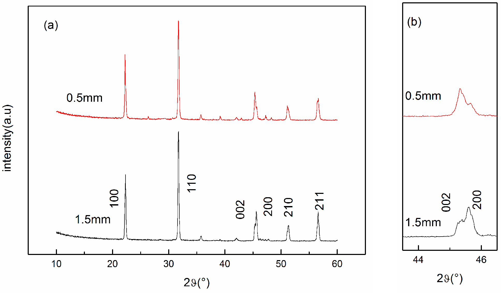
Figure 1. (a) X-ray diffraction (XRD) patterns of the ceramics before(in red) and after grinding(in black); (b) partly enlarged picture of (a).
Inorganics 12 00018 g001
Figure 2. Scanning electron microscopy (SEM) microstructures of the surfaces before grinding (a) and after grinding (b).
Inorganics 12 00018 g002
Figure 3. PE loops.
Figure 3. PE loops.
Inorganics 12 00018 g003
Figure 4. SE curves.
Inorganics 12 00018 g004
Figure 5. The structure to avoid short circuits through the the insulation layers coated on the sides (a) and the certain margin left at the edge (b).
Inorganics 12 00018 g005
Figure 6. (a) Photographs of the test device, (b) partly enlarged picture of (a).
Inorganics 12 00018 g006
Figure 7. Voltage–displacement curve.
Inorganics 12 00018 g007
Table 1. Lattice constants of piezoelectric ceramics.
Thicknessa(Å)b(Å)c(Å)c/a
1.5 mm7.94967.94967.99471.0057
0.5 mm8.00257.88027.93950.9921
Table 2. Physical properties of piezoelectric ceramics.
Samplesd33 (pC/N)εrDensity (g/cm3)
1.5 mm-thick1981299.54.56
0.5 mm-thick2681393.44.60
Disclaimer/Publisher’s Note: The statements, opinions and data contained in all publications are solely those of the individual author(s) and contributor(s) and not of MDPI and/or the editor(s). MDPI and/or the editor(s) disclaim responsibility for any injury to people or property resulting from any ideas, methods, instructions or products referred to in the content.