Abstract
Metal dopants are important for HfO2-based resistive switching mechanisms in resistive random-access memory (RRAM) because they can improve the performance of RRAM devices. Although Cu ions have been widely explored as metal dopants, Cu dopants with different valence states have received little attention. Using the first principles method and the Vienna ab initio simulation package (VASP), the effect of electron gain or loss in different doped Cu states in hafnium oxide (HfO2) was investigated. The electron affinity, defect formation energy, and charge density difference suggest that Cu doping results in a loss of electrons, thereby stabilizing the system. The population, the isosurface of partial charge density, and the migration barrier of the Cu-doped systems with different ionic valence states (+2 and 0) were calculated. Furthermore, the impact of doping ions on the formation of conductive filaments and the stability of the system were investigated in this study. The results indicate that the average population of the Cu-doped (+2) system is smaller than that of the Cu (0) system, and the Cu-O bond length increases in the Cu-doped (+2) system. At the same isosurface level, the electronic local clusters in the Cu (+2) system are stable; however, by increasing the isosurface level, the conductive filament of the Cu (0) system breaks first. At the same starting and ending positions, the migration barrier of the Cu (+2) system was much lower. In the transition state of the Cu (+2) system, the number of atoms whose atomic structure changes by more than 0.1 Å is lower than that in the Cu (0) system, which has a relatively small displacement deviation. This study, which indicates that the Cu (+2) system helps to form conductive channels upon applying current or voltage, can provide theoretical guidance for preparing RRAM and improving its performance.
1. Introduction
CMOS scaling has gradually slowed down in recent years owing to the fundamental limitations associated with the physics of conventional silicon field-effect transistors [1]. Among the emerging in-memory processing candidates, resistive random-access memory (RRAM) has shown outstanding performance in terms of speed and reliability [2,3,4]. It can store data by switching between the high-resistance state (HRS) and low-resistance state (LRS). One of the most important physical mechanisms associated with resistive switching (RS) is the formation and rupture of nanofilaments across dielectric films [5,6].
At present, many experimental and theoretical calculations show that doping improves the electrical properties of RRAM devices and effectively adjusts the type and distribution of defects in resistive materials to change their electrochemical storage characteristics [6,7]. Experimentally, it has been shown that the device forms a conductive channel in Al-doped TiOx systems [8]. In addition, element mapping in TEM shows that the main component of the conductive channel in the Ag/ZrO2/Cu NC/Pt device is Ag, implying that Ag impurities form the conductive channel directly [9]. The first-principles calculation by Maoxiu et al. [10] suggests that Ag impurities can directly participate in the formation of the conductive channel only when it is doped at a specific position.
Waser et al. [11] suggested that the resistance of this kind of RRAM device changes due to the formation or destruction of metallic conductive filaments in the film. The first-principles calculation by Xiao et al. [12] demonstrated that metallic conductive channels could be formed in Cu/Ta2O5/Pt devices, and ionized Cu plays an important role in the formation of conductive filaments [13]. Traoré et al. [14] experimentally studied the influence of metal electrodes on resistive switching and the stability of conductive filaments, and the results are consistent with the calculations. As for the advantages of the practical use of this type of RRAM, Ielmini et al. [15] designed a cross-bar configuration to make the simple architecture of the devices, and Cavallini et al. demonstrated the possibility of regenerating the devices [16].
During the formation of metallic Cu and Ag conductive channels in resistive materials, the effect of the valence state of the dopant on the properties of the resistive materials and devices must be considered. We believe that many additional details, the physical mechanism of the formation of conductive channels in resistive materials, and the ionization state of these metals still need to be explored. In this study, by controlling the valence state of doped elements in HfO2-based RRAM resistive materials and by combining parallel computing and first principles, the effect of different valence states of the doped metals has been investigated using multilevel and multi-dimensional simulation methods.
2. Calculation Theory: Model and Method
Ab initio DFT calculations were performed based on the projector augmented wave method, as implemented in the VASP [17,18]. The generalized gradient approximation (GGA) was used to describe the exchange-correlation function [19]. A plane-wave basis set with a cutoff energy of 500 eV and 3 × 3 × 3 grids was adopted for the Brillouin zone. The atomistic geometries were fully relaxed until the force on each atom was less than 0.015 eV/Å. A jellium background was used to neutralize the lattice while calculating the charged defects. A supercell (2 × 2 × 2) of monoclinic HfO2 containing 96 atoms was constructed, as shown in Figure 1.
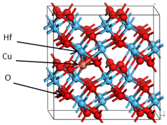
Figure 1.
Supercell crystal structure of HfO2 (red, blue, and brown spheres represent O ions, Hf ions, and Cu ion, respectively).
3. Results and Analysis
3.1. Valence Determination
After the electron affinity energy model is modified, the electronic capture behavior can provide an estimate of the electronic ability. The trapping ability of the hole then defines the loss in electronic ability. The formula is given by the difference between the affinity energies of the intrinsic supercell system and the doping system, as follows [20]:
Eq=0, Eq=+1, and are the total energies of the supercell and the supercell containing defects in neutral, negative, and positive charge states, respectively. The subscript in χ denotes the type of system (bulk system or defect system). If the value of the trapped energy is positive, then trapping the corresponding charge carriers will result in the release of energy. Conversely, a negative value of the trapped energy indicates the absorption of energy. The affinity energy can also be used to quantify the ability to trap different charge carriers. A higher value indicates a higher capacity.
The modified electron affinities are listed in Table 1. The electron affinity shows that the ability to lose electrons is greater than the ability to gain electrons. Doped Cu is more likely to lose electrons, which means that it is more likely to exist in a positively charged form. The stability of the composite defect system can be determined by calculating the defect formation. The energy of a pure supercell was calculated, and the effect of doping impurities with different valences and the chemical formula of the doped element were investigated.

Table 1.
Electron affinity of different defect systems.
The formation energy directly affects the ability to form specific defects and the stability of composite defects. The defect formation energies were calculated according to the standard grand canonical formalism. The formation energy is given by
where is the total energy of the supercell containing the defect , and is the total energy of the perfect supercell. is the defect X with charge q, is the valence-band maximum (VBM) of the perfect supercell, and is the Fermi level which is referenced to the valence band maximum (). The shift of the VBM in a defect supercell takes the change of the valence-band maximum caused by the defect into account. is the elemental chemical potential of the interstitial defect.
The formation energy of a defect demonstrates the difficulty of forming a defect in a crystal. The lower the formation energy is, the more stable the system is. Based on the former calculations of electron affinity, the doped Cu is more likely to lose electrons. There are three systems to be built: (1) Cu (0) system without electron loss; (2) Cu (+1) system with one electron loss from Cu; (3) Cu (+2) system with two electrons losses from Cu. When the same Fermi level has been set as 0 eV ( = 0 eV), three different formation energies have been calculated, and the formation energy of the defects in various charge states at the VBM ( = 0 eV) are given in Table 2.

Table 2.
Defect formation energies in HfO2 at VBM ( ).
From Table 2, under the same Fermi level, the formation energy of the Cu (0) system is the highest (4.813 eV), while the formation energy of the Cu system with a (+2) valence state is the lowest (1.863 eV). In other words, the defect Cu (+2) is relatively easily formed in HfO2; that is, the existence of the +2 valence state is favorable, and the Cu (+2) system is more stable.
3.2. Charge Density Difference and Bader Analysis
The charge density difference is used to visualize the distribution of trapped charge carriers around the defect. Figure 2a shows the differential charge density distribution of Cu after losing two electrons (+2). In the figure, the position of the doping elements is marked by a black circle, and the yellow cloud is the isosurface level of the charge density difference. The charge density difference in the inner region of the isosurface is larger than that on the isosurface, whereas the electron charge density on the outer region is smaller than that on the isosurface. The lost electronic charges (yellow isosurface) were localized around the doped metal atoms (Cu). This indicates that the differential electron charge density here is larger than that in other locations in the supercell, making this region more prone to electron transfer. The electron loss in the system occurs from the doping elements. If an appropriate voltage is applied, the conductive filament channel may be one of the most easily formed channels around the doped elements.
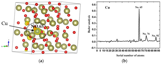
Figure 2.
(a) Charge density difference of Cu (+2) (red and brown spheres represent O ions and Hf ions, Cu ion is wrapped in yellow); (b) graph representing the modified Bader analysis of Cu (+2).
The Bader charge analysis, in which the charge enclosed within the Bader volume is calculated, is a good method for approximating the total electronic charge of an atom. The location of the conductive channel in the storage cell is a crucial aspect in RRAM. In this study, the charge of a single atom in a crystal was calculated by the modified Bader analysis (which considers the difference between the valence state and non-valence state of the Bader charge), and the dynamic charge carriers that were obtained or lost were extracted.
The case in which two electrons are lost from Cu is considered. To determine the location at which the specific charges of the two lost electrons are distributed, the modified Bader analysis was performed (Figure 2b). The x-axis represents the atomic numbers in the system, which can be correlated to the atoms shown in Figure 2a. The y axis represents the specific charge distribution. Most of the two electrons lost by Cu are distributed on atom number 65. The CHGCAR file indicates that No. 65 is a Cu atom. The second highest distribution of electrons can be found in atom numbers 76 and 92, which are located near the doped Cu ions. The distribution of the remaining atoms can be ignored. This shows that the three atoms (especially atom number 65) have the greatest ability to capture the carrier charge, and the lost charges are concentrated at these positions.
3.3. Mulliken Population Analysis of Different Valence States
The Mulliken population refers to the distribution of electrons in the orbits of each atom. The results of the calculations for the HfO2 system doped with Cu (0) and Cu (+2) are given in Table 3.

Table 3.
Mulliken population analysis.
For both the Cu (0) and Cu (+2) systems, the Hf-O population and Hf-O bond length did not change significantly (Table 3). However, the average Mulliken population of the Cu (+2) system (0.0229) was smaller than that of the Cu (0) system (0.107) and corresponded to a difference of 0.0841. The average bond length increased from 2.1601 to 2.3718 (corresponding to a difference of 0.2117). Therefore, the change in the Mulliken population and the bond length in the Cu (+2) system shows that this system is more favorable for Cu ion migration. The increased migration improved the electrochemical performance of the RRAM.
3.4. Influence of Conductive Channels on the Valence States
The formation of conductive Cu channels was investigated using the method described by Kresse et al. [17]. For the Cu (0) and Cu (+2) systems, the isosurface plots of the partial charge density of the impurity energy were calculated, as shown in Figure 3.
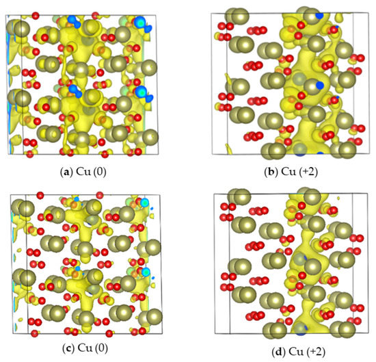
Figure 3.
Isosurface plot of the partial charge density of the (a) Cu (0) and (b) Cu (+2) systems (isosurface level = 0.001) and the (c) Cu (0) and (d) Cu (+2) systems (isosurface level = 0.0025) (Red balls are O, brown balls are Cu, and Cu atoms are wrapped in yellow).
Each noisy cell in the system was blended with two Cu atoms in order to highlight the influence of doping on the formation of conductive filaments. At the same isosurface level, the electronic local clusters in the Cu (+2) system are stable; however, upon increasing the isosurface level, the conductive filament of the Cu (0) system breaks (Figure 3c). This suggests that the Cu (+2) system is more conducive to the formation of conductive filaments (Figure 3d). The impurity energy is around 1 eV.
3.5. Comparative Analysis of Migration Barriers
RS occurs mainly due to the formation and fracture of conductive channels, owing to the migration of metal atoms in resistive materials [10]. The migration barriers of Cu and Cu (+2) in HfO2 were calculated using the nudged elastic band (NEB) method. The migration paths are shown in Figure 4a,b. The calculated migration barriers are shown in Figure 4c. The calculated result shows that the migration barrier of Cu (+2) is 5.12 eV at the same initial and terminal positions, which is much smaller than that of the directly doped Cu atom (9.61 eV). The migration barrier is closely related to the operating voltage of a device. This also shows that, under voltage driving, the migration barrier of the Cu (+2) ion is much smaller than that of the directly doped Cu atom (9.61 eV). Oxidized or doped Cu at the pole can migrate more easily in the form of Cu ions in the resistive material, and this will have a great influence on the formation of conductive metal channels.
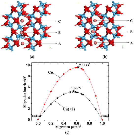
Figure 4.
Migration pathway of (a) Cu (0) and (b) Cu (+2) in HfO2. Positions ‘A’, ‘B’, and ‘C’ represent the initial state, transition state, and final state of Cu migration, respectively (red, blue, and brown spheres represent O ions, Hf ions, and Cu ion, respectively); (c) Migration barrier of Cu (0) and Cu (+2) in HfO2.
3.6. Effects of Different Valence Systems on Stability
The above results suggest that metal migration barriers are different and that each atom structure in the system may move or vibrate to affect the stability of the entire system in the transitional state of migration. Therefore, the transition atoms with different valence states during migration were investigated separately. The structure is shown in Figure 5. Only atoms that migrated to a distance greater than 0.1 Å are listed in Table 4.
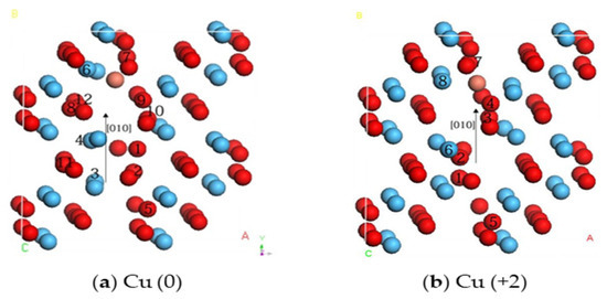
Figure 5.
Atomic structures of the transition state in the migration path (red, blue, and brown spheres represent O, Hf, and Cu, respectively. Atoms with a displacement greater than 0.1 Å are marked with numbers).

It is evident from Table 4 that, due to the migration of the Cu (0) and Cu (+2) ions, the surrounding elements experience varying degrees of vibrational displacement. In the Cu (0) system, the number of atoms whose atomic structure is displaced by more than 0.1 Å is higher than that in the Cu (+2) system, with a smaller displacement deviation. Although there is no specific relationship between atomic vibration and the stability of the entire system, a large deviation in the atomic displacement reflects that the system needs a large strain energy. This is also consistent with the calculated migration barriers.
4. Conclusions
Using first-principles calculation and VASP, the gain and loss of electrons in the elements used to dope resistive materials are discussed. The calculated electron affinity, defect formation energy, and differential charge density show that, in a metal-doped system, Cu exists in an ionic state in HfO2 after losing partial electrons, and the defect system is more stable after losing electrons. The effects of different valence states on the resistance of HfO2 materials were studied. The Cu (+2) system is favorable for increasing the migration of Cu ions, which is more conducive to the formation of conductive filaments and the generation of resistance switching characteristics in RRAM devices. Moreover, it could significantly reduce the electroforming voltages and improve the variability of resistive switching. The results can provide theoretical guidance and design tools for improving the preparation method and performance of RRAM devices, thus helping to fabricate better RRAM devices.
Author Contributions
Data curation, J.Y.; formal analysis, J.Y.; funding acquisition, Y.H.; investigation, J.Y.; methodology, J.Y.; project administration, J.C. and Y.H.; supervision, Y.H.; validation, J.C.; writing—original draft, J.Y. and Y.H.; writing—review & editing, J.C. and Y.H. All authors have read and agreed to the published version of the manuscript.
Funding
This work was supported by the Research Foundation of the Education Bureau of Anhui Province, China (Grant No. KJ2019A0735), the German Research Foundation (DFG, Deutsche Forschungsgemeinschaft) as a part of Germany’s Excellence Strategy, EXC 2050/1, Project ID 390696704–Cluster of Excellence “Center for Tactile Internet with Human-in-the-Loop” (CeTI) of Technische Universität Dresden, and the Australian Research Council Centre of Excellence Scheme (CE140100012).
Institutional Review Board Statement
Not applicable.
Informed Consent Statement
Not applicable.
Data Availability Statement
Not applicable.
Acknowledgments
The authors are grateful for the financial support from the Research Foundation of the Education Bureau of Anhui Province, China (Grant No. KJ2019A0735), the German Research Foundation (DFG, Deutsche Forschungsgemeinschaft) as a part of Germany’s Excellence Strategy, EXC 2050/1, Project ID 390696704–Cluster of Excellence “Center for Tactile Internet with Human-in-the-Loop” (CeTI) of Technische Universität Dresden, the Australian Research Council Centre of Excellence Scheme (CE140100012), and Australian National Fabrication Facilities (ANFF)—Materials Node at University of Wollongong.
Conflicts of Interest
The authors declare no conflict of interest.
References
- Chiang, C.-C.; Ostwal, V.; Wu, P.; Pang, C.-S.; Zhang, F.; Chen, Z.; Appenzeller, J. Memory applications from 2D materials. Appl. Phys. Rev. 2021, 8, 021306. [Google Scholar] [CrossRef]
- Valov, L.; Michael, N.K. Cation-based resistance change memory. Phys. D Appl. Phys. 2013, 46, 074005. [Google Scholar] [CrossRef]
- Milo, V.; Zambelli, C.; Olivo, P.; Pérez, E.; Mahadevaiah, M.K.; Ossorio, O.G.; Wenger, C.; Ielmini, D. Multilevel HfO2-based RRAM devices for low-power neuromorphic networks. APL Mater. 2019, 7, 081120. [Google Scholar] [CrossRef] [Green Version]
- Jena, A.K.; Sahoo, A.K.; Mohanty, J. Effects of magnetic field on resistive switching in multiferroic based Ag/BiFeO3/FTO RRAM device. Appl. Phys. Lett. 2020, 116, 092901. [Google Scholar] [CrossRef]
- Yang, Y.; Pan, F.; Liu, Q.; Liu, M.; Zeng, F. Fully Room-Temperature-Fabricated Nonvolatile Resistive Memory for Ultrafast and High-Density Memory Application. Nano Lett. 2009, 9, 1636–1643. [Google Scholar] [CrossRef] [PubMed]
- Lanza, M.; Wong, H.-S.P.; Pop, E.; Ielmini, D.; Shi, Y. Recommended methods to study resistive switching devices. Adv. Electron. Mater. 2019, 5, 1800143. [Google Scholar] [CrossRef] [Green Version]
- Frascaroli, J.; Volpe, F.G.; Brivio, S.; Spiga, S. Effect of Al doping on the retention behavior of HfO2 resistive switching memories. Microelectron. Eng. 2015, 147, 104–107. [Google Scholar] [CrossRef]
- Trapatseli, M.; Khiat, A.; Cortese, S.; Serb, A.; Carta, D.; Prodromakis, T. Engineering the switching dynamics of TiOx-based RRAM with Al doping. J. Appl. Phys. 2016, 120, 025108. [Google Scholar] [CrossRef]
- Liu, Q.; Long, S.; Lv, H.; Wang, W.; Niu, J.; Huo, Z.; Chen, J.; Liu, M. Controllable Growth of Nanoscale Conductive Filaments in Solid-Electrolyte-Based ReRAM by Using a Metal Nanocrystal Covered Bottom Electrode. ACS Nano 2010, 4, 6162–6168. [Google Scholar] [CrossRef]
- Maoxiu, Z.; Qiang, Z.; Wei, Z.; Liu, Q.; Dai, Y. The conductive path in HfO2: First principles study. J. Semicond. 2012, 33, 072002. [Google Scholar]
- Waser, B.R.; Dittmann, R.; Staikov, G.; Szot, K. Redox-based resistive switching memories–nanoionic mechanisms, prospects, and challenges. Adv. Mater. 2009, 21, 2632–2663. [Google Scholar] [CrossRef]
- Xiao, B.; Watanabe, S. Interface Structure in Cu/Ta2O5/Pt Resistance Switch: A First-Principles Study. ACS Appl. Mater. Interfaces 2015, 7, 519–525. [Google Scholar] [CrossRef] [PubMed]
- Xiao, B.; Gu, T.K.; Tada, T.; Watanabe, S. Conduction paths in Cu/amorphous-Ta2O5/Pt atomic switch: First-principles studies. J. Appl. Phys. 2014, 115, 034503. [Google Scholar] [CrossRef] [Green Version]
- Traore, B.; Blaise, P.; Vianello, E.; Grampeix, H.; Jeannot, S.; Perniola, L.; De Salvo, B.; Nishi, Y. On the Origin of Low-Resistance State Retention Failure in HfO2-Based RRAM and Impact of Doping/Alloying. IEEE Trans. Electron. Devices 2015, 62, 4029–4036. [Google Scholar] [CrossRef]
- Ielmini, D.; Wong, H.-S.P. In-memory computing with resistive switching devices. Nat. Electron. 2018, 1, 333–343. [Google Scholar] [CrossRef]
- Cavallini, M.; Hemmatian, Z.; Riminucci, A.; Prezioso, M.; Morandi, V.; Murgia, M. Regenerable Resistive Switching in Silicon Oxide Based Nanojunctions. Adv. Mater. 2012, 24, 1197–1201. [Google Scholar] [CrossRef] [PubMed]
- Kresse, G.; Joubert, D. From ultrasoft pseudopotentials to the projector augmented-wave method. Phys. Rev. B 1999, 59, 1758–1775. [Google Scholar] [CrossRef]
- Kresse, G.; Furthmüller, J. Efficient iterative schemes for ab initio total-energy calculations using a plane-wave basis set. Can. Metall. Q. 1996, 54, 11169. [Google Scholar]
- Perdew, J.P.; Burke, K.; Ernzerhof, M. Generalized gradient approximation made simple. Phys. Rev. Lett. 1997, 77, 3865. [Google Scholar] [CrossRef] [PubMed] [Green Version]
- Gritsenko, V.; Nekrashevich, S.; Vasilev, V.; Shaposhnikov, A. Electronic structure of memory traps in silicon nitride. Microelectron. Eng. 2009, 86, 1866–1869. [Google Scholar] [CrossRef]
Publisher’s Note: MDPI stays neutral with regard to jurisdictional claims in published maps and institutional affiliations. |
© 2022 by the authors. Licensee MDPI, Basel, Switzerland. This article is an open access article distributed under the terms and conditions of the Creative Commons Attribution (CC BY) license (https://creativecommons.org/licenses/by/4.0/).