High-Order Modes Suppression in All-Glass Large-Mode Area Rare-Earth Doped Optical Fibers with Modified Cladding

 ,
, 
Abstract
:1. Introduction
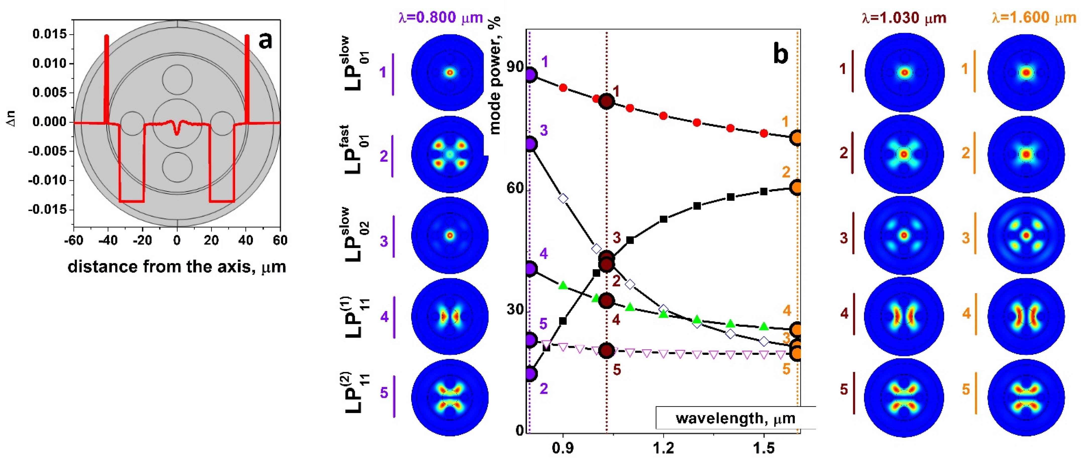
2. Fiber Modelling
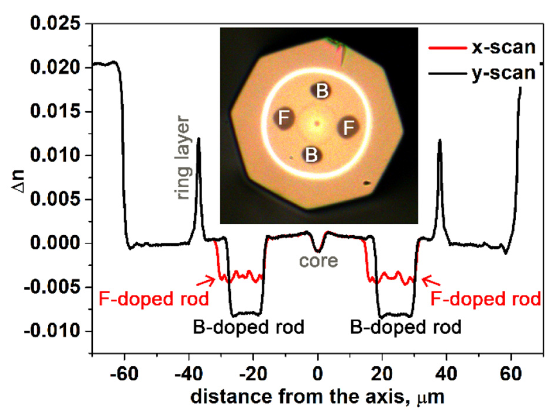
3. Materials and Methods
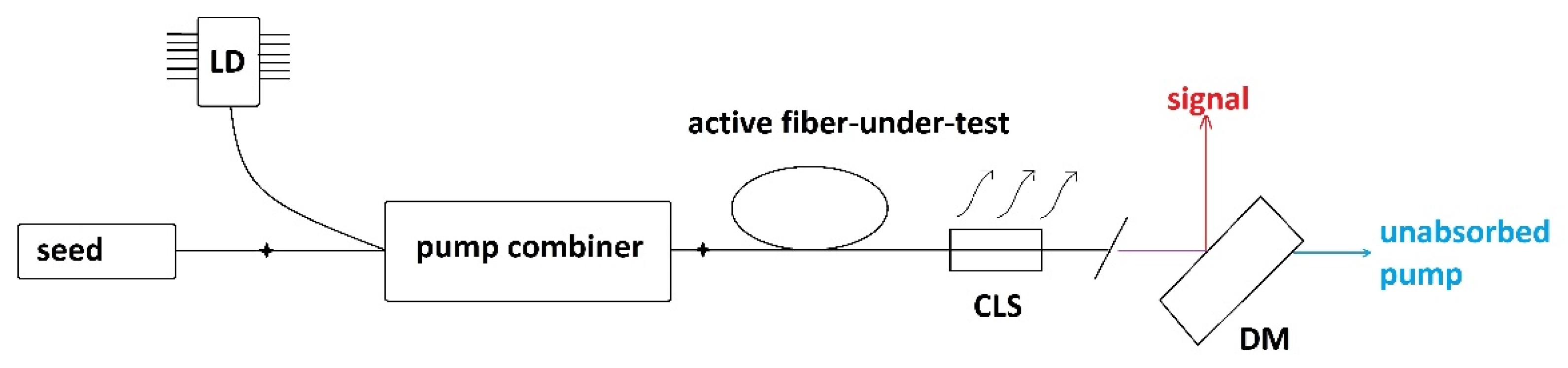
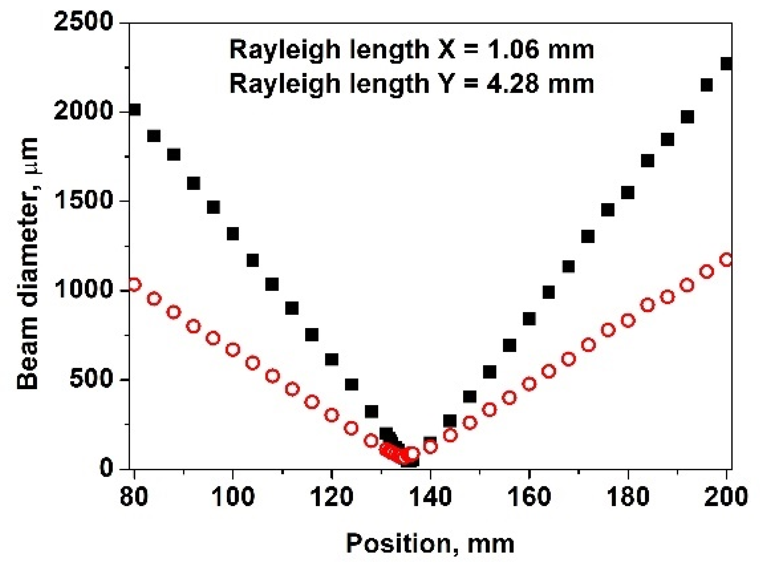
4. Experiment and Results
4.1. Yb-Doped Fiber
4.2. Er-Doped Fiber
5. Conclusions
Author Contributions
Funding
Institutional Review Board Statement
Informed Consent Statement
Data Availability Statement
Acknowledgments
Conflicts of Interest
References
- Phillips, K.C.; Gandhi, H.H.; Mazur, E.; Sundaram, S.K. Ultrafast laser processing of materials: A review. Adv. Opt. Photon. 2015, 7, 684–712. [Google Scholar] [CrossRef]
- Cariou, J. Performances and applications of coherent pulsed fiber lidars in atmospheric sensing. In Proceedings of the Laser Congress (ASSL, LAC, LS&C), Vienna, Austria, 29 September–3 October 2019; OSA Technical Digest. Optica Publishing Group: West Perth, Australia, 2019; p. LW1B.2. [Google Scholar]
- Cézard, N.; Dolfi-Bouteyre, A.; Durécu, A.; Faure, B.; Goular, D.; Gustave, F.; Hébert, P.-J.; Lahyani, J.; Gouët, J.L.; Lemaître, F.; et al. Recent advances on fiber-based laser and Lidar systems for future space-borne monitoring of greenhouse gas. Proc. SPIE 2021, 11852, 791–799. [Google Scholar] [CrossRef]
- Kim, K.; Song, M.-K.; Lee, S.-J.; Shin, D.; Suh, J.; Kim, J.-D. Fundamental study on underwater cutting of 50 mm-thick stainless steel plates using a fiber laser for nuclear decommissioning. Appl. Sci. 2022, 12, 495. [Google Scholar] [CrossRef]
- Kopyeva, M.S.; Filatova, S.A.; Kamynin, V.A.; Trikshev, A.I.; Kozlikina, E.I.; Astashov, V.V.; Loschenov, V.B.; Tsvetkov, V.B. Ex-vivo exposure on biological tissues in the 2-μm spectral range with an all-fiber continuous-wave holmium laser. Photonics 2022, 9, 20. [Google Scholar] [CrossRef]
- Stutzki, F.; Jansen, F.; Otto, H.-J.; Jauregui, C.; Limpert, J.; Tünnermann, A. Designing advanced very-large-mode-area fibers for power scaling of fiber-laser systems. Optica 2014, 1, 233–242. [Google Scholar] [CrossRef]
- Eidam, T.; Rothhardt, J.; Stutzki, F.; Jansen, F.; Hadrich, S.; Carstens, H.; Jauregui, C.; Limpert, J.; Tünnermann, A. Fiber chirped-pulse amplification system emitting 3.8 GW peak power. Opt. Express 2011, 19, 255–260. [Google Scholar] [CrossRef]
- Röser, F.; Jauregui, C.; Limpert, J.; Tünnermann, A. 94 W 980 nm high brightness Yb-doped fiber laser. Opt. Express 2008, 16, 17310–17318. [Google Scholar] [CrossRef]
- Boullet, J.; Zaouter, Y.; Desmarchelier, R.; Cazaux, M.; Salin, F.; Saby, J.; Bello-Doua, R.; Cormier, E. High power ytterbium-doped rod-type three-level photonic crystal fiber laser. Opt. Express 2008, 16, 17891–17902. [Google Scholar] [CrossRef]
- Gaida, C.; Gebhardt, M.; Heuermann, T.; Stutzki, F.; Jauregui, C.; Limpert, J. Ultrafast thulium fiber laser system emitting more than 1 kW of average power. Opt. Lett. 2018, 43, 5853–5856. [Google Scholar] [CrossRef]
- Stutzki, F.; Gaida, C.; Gebhardt, M.; Jansen, F.; Jauregui, C.; Limpert, J.; Tünnermann, A. Tm-based fiber-laser system with more than 200 MW peak power. Opt. Lett. 2015, 40, 9–12. [Google Scholar] [CrossRef]
- Kotov, L.V.; Likhachev, M.E.; Bubnov, M.M.; Medvedkov, O.I.; Yashkov, M.V.; Guryanov, A.N.; Lhermite, J.; Février, S.; Cormier, E. 75 W 40% efficiency single-mode all-fiber erbium-doped laser cladding pumped at 976 nm. Opt. Lett. 2013, 38, 2230–2232. [Google Scholar] [CrossRef]
- Kotov, L.; Likhachev, M.; Bubnov, M.; Medvedkov, O.; Lipatov, D.; Guryanov, A.; Zaytsev, K.; Jossent, M.; Février, S. Millijoule pulse energy 100-nanosecond Er-doped fiber laser. Opt. Lett. 2015, 40, 1189–1192. [Google Scholar] [CrossRef]
- Gaponov, D.A.; Kotov, L.V.; Likhachev, M.E.; Bubnov, M.M.; Cabasse, A.; Oudar, J.-L.; Fevrier, S.; Lipatov, D.S.; Vechkanov, N.N.; Guryanov, A.N.; et al. High power all-fibered femtosecond master oscillator power amplifier at 1.56 μm. Opt. Lett. 2012, 37, 3186–3188. [Google Scholar] [CrossRef] [PubMed]
- Bobkov, K.; Andrianov, A.; Koptev, M.; Muravyev, S.; Levchenko, A.; Velmiskin, V.; Aleshkina, S.; Semjonov, S.; Lipatov, D.; Guryanov, A.; et al. Sub-MW peak power diffraction-limited chirped-pulse monolithic Yb-doped tapered fiber amplifier. Opt. Express 2017, 25, 26958–26972. [Google Scholar] [CrossRef] [PubMed]
- Bobkov, K.; Levchenko, A.; Kashaykina, T.; Aleshkina, S.; Bubnov, M.; Lipatov, D.; Laptev, A.; Guryanov, A.; Leventoux, Y.; Granger, G.; et al. Scaling of average power in sub-MW peak power Yb-doped tapered fiber picosecond pulse amplifiers. Opt. Express 2021, 29, 1722–1735. [Google Scholar] [CrossRef] [PubMed]
- Fedotov, A.; Noronen, T.; Gumenyuk, R.; Ustimchik, V.; Chamorovskii, Y.; Golant, K.; Odnoblyudov, M.; Rissanen, J.; Niemi, T.; Filippov, V. Ultra-large core birefringent Yb-doped tapered double clad fiber fiber high power amplifiers. Opt. Express 2018, 26, 6581–6592. [Google Scholar] [CrossRef] [PubMed]
- Lai, W.; Ma, P.; Liu, W.; Huang, L.; Li, C.; Ma, Y.; Zhou, P. 550 W single frequency fiber amplifiers emitting at 1030 nm based on a tapered Yb-doped fiber. Opt. Express 2020, 28, 20908–20919. [Google Scholar] [CrossRef]
- Khudyakov, M.M.; Levchenko, A.E.; Velmiskin, V.V.; Bobkov, K.K.; Aleshkina, S.S.; Bubnov, M.M.; Yashkov, M.V.; Gur’yanov, A.N.; Kotov, L.V.; Likhachev, M.E. Er-Doped Tapered Fiber Amplifier for High Peak Power Sub-ns Pulse Amplification. Photonics 2021, 8, 523. [Google Scholar] [CrossRef]
- Bobkov, K.K.; Lipatov, D.S.; Salgansky, M.Y.; Guryanov, A.N.; Bubnov, M.M.; Likhachev, M.E. All-fiber chirped-pulse amplifier emitting 670 fs pulses with 92 MW peak power. Photon. Techn. Lett. 2022. in print. [Google Scholar] [CrossRef]
- Bobkov, K.K.; Mikhailov, E.K.; Zaushitsyna, T.S.; Rybaltovsky, A.A.; Aleshkina, S.S.; Melkumov, M.A.; Bubnov, M.M.; Lipatov, D.S.; Yashkov, M.V.; Abramov, A.N.; et al. Properties of silica based optical fibers doped with an ultra-high ytterbium concentration. J. Lightwave Technol. 2022. early posted. [Google Scholar] [CrossRef]
- Sidharthan, R.; Lin, D.; Lim, K.J.; Li, H.; Lim, S.H.; Chang, C.J.; Seng, Y.M.; Chua, S.L.; Jung, Y.; Richardson, D.J.; et al. Ultra-low NA step-index large mode area Yb-doped fiber with a germanium doped cladding for high power pulse amplification. Opt. Lett. 2020, 45, 3828–3831. [Google Scholar] [CrossRef]
- Aleshkina, S.S.; Likhachev, M.E.; Pryamikov, A.D.; Gaponov, D.A.; Denisov, A.N.; Bubnov, M.M.; Salganskii, M.Y.; Laptev, A.Y.; Guryanov, A.N.; Uspenskii, Y.A.; et al. Very-large-mode-area photonic bandgap Bragg fiber polarizing in a wide spectral range. Opt. Lett. 2011, 36, 3566–3568. [Google Scholar] [CrossRef]
- Gaponov, D.A.; Février, S.; Devautour, M.; Roy, P.; Likhachev, M.E.; Aleshkina, S.S.; Salganskii, M.Y.; Yashkov, M.V.; Guryanov, A.N. Management of the high-order mode content in large (40 μm) core photonic bandgap Bragg fiber laser. Opt. Lett. 2010, 35, 2233–2235. [Google Scholar] [CrossRef] [PubMed]
- Yablon, A.D.; Yan, M.F.; DiGiovanni, D.J.; Lines, M.E.; Jones, S.L.; Ridgway, D.N.; Sandels, G.A.; White, I.A.; Wisk, P.; DiMarcello, F.V.; et al. Frozen-in viscoelasticity for novel beam expanders and high-power connectors. J. Lightwave Technol. 2004, 22, 16–23. [Google Scholar] [CrossRef]
- Aleshkina, S.S.; Bardina, T.L.; Lipatov, D.S.; Bobkov, K.K.; Bubnov, M.M.; Guryanov, A.N.; Likhachev, M.E. Factors reducing the efficiency of ytterbium fibre lasers and amplifiers operating near 0.98 μm. Quant. Electron. 2017, 47, 1109–1114. [Google Scholar] [CrossRef]
- Siegman, A.E. Defining, measuring, and optimizing laser beam quality. Proc. SPIE 1993, 1868, 2–12. [Google Scholar] [CrossRef]
- Nicholson, J.W.; Yablon, A.D.; Ramachandran, S.; Ghalmi, S. Spatially and spectrally resolved imaging of modal content in large-mode-area fibers. Opt. Express 2008, 16, 7233–7243. [Google Scholar] [CrossRef]
- Nicholson, J.W.; Yablon, A.D.; Fini, J.M.; Mermelstein, M.D. Measuring the modal content of large-mode-area fibers. IEEE J. Sel. Top. Quant. Electron. 2009, 15, 61–70. [Google Scholar] [CrossRef]
- Aleshkina, S.S.; Likhachev, M.E.; Pryamikov, A.D.; Gaponov, D.A.; Denisov, A.N.; Semjonov, S.L.; Bubnov, M.M.; Salganskii, M.Y.; Guryanov, A.N. Large-mode-area Bragg fiber with microstructured core for suppression of high-order modes. Proc. SPIE 2010, 7714, 262–272. [Google Scholar] [CrossRef]


Publisher’s Note: MDPI stays neutral with regard to jurisdictional claims in published maps and institutional affiliations. |
© 2022 by the authors. Licensee MDPI, Basel, Switzerland. This article is an open access article distributed under the terms and conditions of the Creative Commons Attribution (CC BY) license (https://creativecommons.org/licenses/by/4.0/).
Share and Cite
Aleshkina, S.S.; Khudyakov, M.M.; Kashaykina, T.A.; Yashkov, M.V.; Salganskii, M.Y.; Velmiskin, V.V.; Bubnov, M.M.; Likhachev, M.E. High-Order Modes Suppression in All-Glass Large-Mode Area Rare-Earth Doped Optical Fibers with Modified Cladding. Photonics 2022, 9, 623. https://doi.org/10.3390/photonics9090623
Aleshkina SS, Khudyakov MM, Kashaykina TA, Yashkov MV, Salganskii MY, Velmiskin VV, Bubnov MM, Likhachev ME. High-Order Modes Suppression in All-Glass Large-Mode Area Rare-Earth Doped Optical Fibers with Modified Cladding. Photonics. 2022; 9(9):623. https://doi.org/10.3390/photonics9090623
Chicago/Turabian StyleAleshkina, Svetlana S., Maxim M. Khudyakov, Tatiana A. Kashaykina, Mikhail V. Yashkov, Mikhail Yu. Salganskii, Vladimir V. Velmiskin, Mikhail M. Bubnov, and Mikhail E. Likhachev. 2022. "High-Order Modes Suppression in All-Glass Large-Mode Area Rare-Earth Doped Optical Fibers with Modified Cladding" Photonics 9, no. 9: 623. https://doi.org/10.3390/photonics9090623
APA StyleAleshkina, S. S., Khudyakov, M. M., Kashaykina, T. A., Yashkov, M. V., Salganskii, M. Y., Velmiskin, V. V., Bubnov, M. M., & Likhachev, M. E. (2022). High-Order Modes Suppression in All-Glass Large-Mode Area Rare-Earth Doped Optical Fibers with Modified Cladding. Photonics, 9(9), 623. https://doi.org/10.3390/photonics9090623