Review

Fiber Lasers Based on Dynamic Population Gratings in Rare-Earth-Doped Optical Fibers

by
Nikita R. Poddubrovskii
1,2,
Roman V. Drobyshev
1,
Ivan A. Lobach
1,* and
Sergey I. Kablukov
1,*
1
Institute of Automation and Electrometry, Siberian Branch of the Russian Academy of Sciences, 1 Ac. Koptyug Ave., Novosibirsk 630090, Russia
2
Department of Physics, Novosibirsk State University, 2 Pirogova Str., Novosibirsk 630090, Russia
*
Authors to whom correspondence should be addressed.
Photonics 2022, 9(9), 613; https://doi.org/10.3390/photonics9090613
Submission received: 29 July 2022 / Revised: 25 August 2022 / Accepted: 25 August 2022 / Published: 29 August 2022
(This article belongs to the Special Issue Rare Earth Doped Fiber Lasers)

Abstract

:
Long dynamic population gratings (DPGs) formed in rare-earth-doped fibers have unique spectral characteristics compared to other types of fiber gratings, making them suitable for controlling the spectral composition of lasers. Depending on the type, length, and position of the DPGs in the cavities of lasers, they can be used for various purposes, ranging from the stabilization of single-frequency radiation to regular wavelength self-sweeping (WLSS) operation. Lasers based on DPGs are sources of narrow-band radiation with a fixed or sweeping generation spectrum. One of the main advantages of such lasers is the simplicity of their design, since they do not require special spectral elements or drivers for spectrum control. In this paper, we review the research progress on fiber lasers based on DPGs. The basic working principles of different types of DPGs will be introduced in the theoretical section. The operation of lasers based on absorption and gain DPGs and their practical applications will be discussed and summarized in experimental section. Finally, the main challenges for the development of such lasers will be presented.

1. Introduction

Fiber lasers are one of the most significant achievements of laser physics [1,2]. Among the advantages of fiber lasers, one can note their compactness, the high quality of their output beam (up to fundamental mode), their efficient heat removal, high power, the variety of generation regimes, etc. Due to these properties, fiber lasers can be used in lieu of other laser sources, and in some cases, even replace them. Fiber lasers are used for sensing [3,4], materials processing [5], in telecommunications [2,6], in LIDAR systems [2,6,7], etc. The most widely investigated fiber lasers providing laser generation in nearly the entire near-IR range (from 0.92 to 2.1 μm) are based on fibers doped with rare-earth (RE) elements [1,2,8]. The all-fiber scheme of such lasers has become possible thanks to one of the key elements of fiber optics—fiber Bragg gratings (FBGs). An FBG is a piece of fiber with a permanently induced artificial modulation of the refractive index (RI) [8]. Such artificial RI structures are formed using UV- [8,9,10] or femtosecond-radiation [11,12]. The unique spectral properties of FBGs are used to control the spectral characteristics of the radiation produced by fiber lasers. However, the length of FBGs is limited by the precision of the technology used, which, in turn, limits the possibilities of spectral control. The main advantage of long FBGs is the possibility of obtaining a narrow reflection spectrum. Nevertheless, ~30-cm-long FBGs have been used in Raman-DFB lasers [13]. Special error-correction techniques are used during recording to obtain ultra-long FBGs with a length of up to 1 m [14]. For example, the reflection spectrum bandwidth was reduced to about a picometer in [14], while it is fractions of a nanometer for conventional millimeters-long FBGs. It should be noted that the reflectance of a homogeneous FBG is proportional to the square of the product of the RI modulation amplitude and its length in the limit of low reflectance [8]. Consequently, even a small RI modulation can lead to a noticeable reflectance value with a large FBG length. Relatively recently, interest has arisen in fiber gratings of a different type, in which a small RI modulation exists over a relatively long length. In this case, the RI modulation may no longer be strictly periodic. However, the gratings with random RI modulation, in contrast to periodic ones, have multiple random peaks in their reflection spectra. Nevertheless, bandwidths of the reflection peaks can be rather narrow, and the gratings can be used to match the reflection of some of the peaks to another narrowband reflector (see, for example, [15]).
Fiber gratings with small random RI modulations are used, for example, to artificially increase backscattered signals [16,17]. To create such long fiber gratings, one can apply the aforementioned standard grating fabrication techniques (with UV or femtosecond radiation) during the fiber drawing process (see, for example, [18,19]). In fact, such a structure is a long and continuous array of many weakly reflecting random FBGs. The advantage of this structure is its high spectral selectivity up to the selection of a single longitudinal mode (SLM) [16]. Another way to form a low-reflectance fiber grating is to use a long piece of standard optical fiber with Rayleigh scattering. The random distribution of weak scatterers associated with the presence of frozen RI inhomogeneities can lead to the formation of weak FBGs for predetermined wavelengths at large fiber lengths (on large samples of such random fluctuations). The presence of weak RI inhomogeneities frozen into standard optical fibers has led to the emergence of random distributed feedback fiber lasers [20]. The simplicity of the laser design based on random distributed feedback, associated with the absence of the need to use point mirrors, has attracted the attention of many researchers. Moreover, such lasers have additional advantages. For example, optimization of the laser parameters make it possible to achieve a generation efficiency approaching “ideal” quantum efficiency [21]. However, for high-efficiency lasers, it was necessary to shorten the fiber length and significantly increase the pump power. A high lasing threshold is associated with low reflectance. A length decrease can also be achieved without increasing the pump power by increasing the RI modulation, which was done in the aforementioned papers [16,17].
Another type of long fiber grating can have regular RI modulation instead of random modulation. In particular, this class includes fiber dynamic gratings with finite lifetimes, such as dynamic Brillouin gratings (DBG) [22,23] and dynamic population gratings (DPG) in active fibers [24]. Such dynamic gratings are formed due to the local impact of narrow-band radiation on the parameters of active fibers. In the case of highly coherent radiation with a long coherence length, one can expect long gratings to form with regular RI modulation. In contrast to the previously considered permanent gratings, dynamic ones disappear in a short time after shutting down the radiation. A DBG can be formed in standard telecommunication fiber due to electrostriction effect, with a lifetime in the order of several tens of nanoseconds [22]. The lengths of the gratings can reach several hundreds of meters. As a rule, DBGs are used for distributed sensing [22]. The other type of the dynamic gratings—DPG—is associated with population inversion level modulation in RE-doped fibers. DPG formation results from the nonuniform interaction of a standing wave with resonance transitions in RE ions along the fiber length. The presence of intermittent nodes and antinodes corresponding to the low and high intensities of electromagnetic radiation leads to the appearance of alternating zones with high and low population inversion levels, respectively. The DPGs are responsible for several phenomena: first, they act as gain or absorption gratings depending on the population inversion sign; secondly, RI gratings (phase gratings) are also formed, because the local RI of a medium also depends on current states of the active ions. The lifetime of a DPG is determined by the lifetime of the upper level of the active ion and can reach up to 10 ms. The DPG lengths are related both to the length of the RE-doped fiber and to the gain distribution and can be as long as several tens of meters. Such DPG structures can be used both for sensors and lasers applications [22].
The present paper reviews works concerning lasers based on the DPGs formed in RE-doped fibers. This review has the following structure. The theoretical part describes the various types of gratings and their main characteristics. The influence of the grating type on the generation spectrum is also discussed. The experimental part of the work is divided into two sections according to the DPG classification (absorption and gain), describing the opposing effects of DPGs on the laser generation wavelength (stabilization and sweeping). These sections are followed by a discussion of some possible applications of various radiation sources. The main challenges requiring further research are considered in the concluding section.

2. Theoretical Part

DPGs are typically considered as a spatial modulation of levels population with finite lifetimes. Here, we will consider the modulations of gain, absorption, and RI in media doped with RE-elements. Small-scale modulation with a period comparable with the wavelength can be formed in the absorbing or amplifying media as a result of resonance interactions of the media with the standing wave radiation. The standing wave forms an interference pattern along the propagation direction (i.e., the coordinate axis OZ) of two counterpropagating waves [24]:
I(z) = I0(1 + m cos(Kz)),
where I0 is the average intensity of the standing wave, m is modulation depth, and K = 2π/Λ is spatial frequency of the interference pattern corresponding to the spatial modulation period of Λ. The radiation causes the gain saturation g(I) = g0/(1 + I/Isat), where g0 and Isat are the unsaturated gain coefficient and characteristic saturation intensity, respectively. Negative values of the gain coefficient (g(I) and g0 < 0) are considered here as the absorption. In such cases, the saturation is stronger for zones with higher intensity levels. As a result of the saturation effect, the spatial intensity modulation leads to a spatial gain modulation g(z) = gsat + δg cos(Kz), where the values of the average level of the saturated gain gsat and its modulation depth δg can be approximately represented as gsat = g0/(1 + I0/Isat) and δg = −mg0(I0/Isat)/(1 + I0/Isat)2, respectively [24]. In addition, it should be noted that the local gain (as well as absorption) g0 is coupled with the RI n0 via the Kramers-Kronig relation, and the changes of the gain and RI can be described in terms of the complex RI: n ˜ = n0 + ig0c/2ω, where c and ω are the speed of light and radiation optical frequency. In this expression the real and imaginary parts of the complex RI correspond to the conventional RI and gain/absorption of the medium, respectively. Expression for the modulation amplitude of the complex RI with respect to the mean value can be written in a similar way:   δ n ˜ = δn + iδg c/2ω. It should be also noted that the modulation amplitudes of two components of the DPGs (δn and δg) are coupled with each other, and the relation between them depends on properties of a considered medium and on the radiation wavelength. Further, discussing amplitude DPGs (gain or absorption), we will keep in mind that phase (RI) DPGs are also present in the medium.
Let us briefly describe the influence of these dynamic structures on the laser generation. We assume that the amplifying/absorbing medium is placed in a linear cavity of a laser that generates SLM radiation. We also assume that the gain/absorption spectrum of the medium does not have sharp spectral features for the traveling waves. First, we will neglect the influence of phase DPGs. The standing wave forms an amplitude DPG in a gain medium, and a narrow spectral dip appears in the gain contour at the optical frequency corresponding to the generated radiation. Such a DPG causes a selective reduction in the integral gain for the generated radiation, which, in turn, causes it to hop to another mode with higher integral gain. The selective gain reduction effect is also known as spatial hole burning (SHB) [25]. The presence of an absorption DPG has the opposite effect. The SHB effect for the absorption spatial distribution causes the appearance of a narrow dip in the absorption spectrum (in the laser cavity loss spectrum), which leads to the stabilization of the generated optical frequency and prevents the laser cavity from hopping to the neighboring modes. When the influence of the phase DPG is considered, the position of the active medium in relation to the cavity mirrors should be taken into account, since the phase DPG causes the formation of a nested cavity in the laser. Additionally, the phase DPG (like a FBG) has a spectral dependence of the reflection coefficient. Moreover, amplitude DPGs have reflective properties as well as phase ones [26].
DPGs have been already observed in various media, e.g., in liquid solutions of organic dyes [27]. Researchers have since distinguished two components of DPGs: amplitude DPG, related to the SHB, and phase DPG, associated with the temperature modulation of the medium. In addition, the presence of DPGs has been observed in semiconductors, where a light wave can influence the charge carriers (holes and electrons), creating a structure similar to that of a DPG [28].
DPGs can be effectively formed in RE-doped optical fibers due to their large length and single transverse mode operation [24,29,30]. In fiber optics, dynamic structures were discovered in early 1990s [31]. The spectral characteristics of DPGs attract attention of researchers. A standing wave needs to be formed in an RE-doped medium to start recording of DPG. In the simplest case, the radiation that formed the DPG can be used for its characterization. In this case the interference pattern of the standing wave should be rapidly shifted, for example, with a fast shift of the mirror position by half a wavelength [32] or by a similar phase change with a phase modulator [33,34,35]. In such experiments, one can measure the lifetime and reflectance of the DPGs at a fixed wavelength. In more complex experiments with tuning of a probe radiation wavelength the full DPG reflection spectrum can be measured [36,37]. In particular, the DPG reflectance was measured to be up to 10% for 0.7-m-long Er-doped fiber in [36]. The lifetime of DPGs is determined by the lifetime of the upper level of the active ion (~1 ms and ~10 ms for ytterbium and erbium ions, respectively), but can decrease due to saturation of the medium parameters and spatial diffusion [24]. The DPGs can act as dynamic spectral filters [38] and thus can be used, for example, in adaptive interferometry [39]. Schemes with DPG placed directly in a laser cavity are of particular interest, since its narrow-band reflection causes spectrally selective changes of the laser cavity quality factor.
The formation of DPGs in laser cavities can lead to the creation of several nested cavities. Generally, it is enough to consider a reflection spectrum of a sub-cavity (compound mirror) containing the DPG and one of the cavity mirrors to describe the influence of the DPG on the laser generation spectrum. Fox-Smith or Michelson reflectors are examples of use of compound mirrors in lasers. In our case, an active Fabry-Perot reflector (FPR) has one mirror formed with a DPG, while the other one corresponds to a cavity mirror (Figure 1). In our case, it is active FPR, because the DPG is recorded in the amplifying or absorbing fiber. The expression for the reflection spectrum of such an active FPR was presented in [40,41] and has the form:
R r Δ k = e 2 g L i π δ n ˜ L λ 1 e g + i 2 Δ k L g + i 2 Δ k L e i 2 Δ k l p f + R 1 2 ,
where λ is the wavelength of the recording radiation, Δk = 2πnΔν/c is the wave vector detuning (the wave vectors mismatch between the recording and probing radiation with frequency detuning of Δν), δ n ˜ is amplitude of the complex DPG, L and g are length and gain coefficient of the active fiber, correspondingly, R1 is the cavity mirror reflection coefficient, lpf is a spacing between mirrors of the active FPR determined by the length of the passive fiber located between the active fiber and the cavity mirror. The common factor exp(2gL) demonstrates influence of non-resonance gain/absorption in the active fiber, depending on the sign of g. The imaginary part sign of the n ˜ should also correspond to the gain sign. The first and last terms in the submodular expression correspond to the reflection from the DPG and the cavity mirror, respectively.
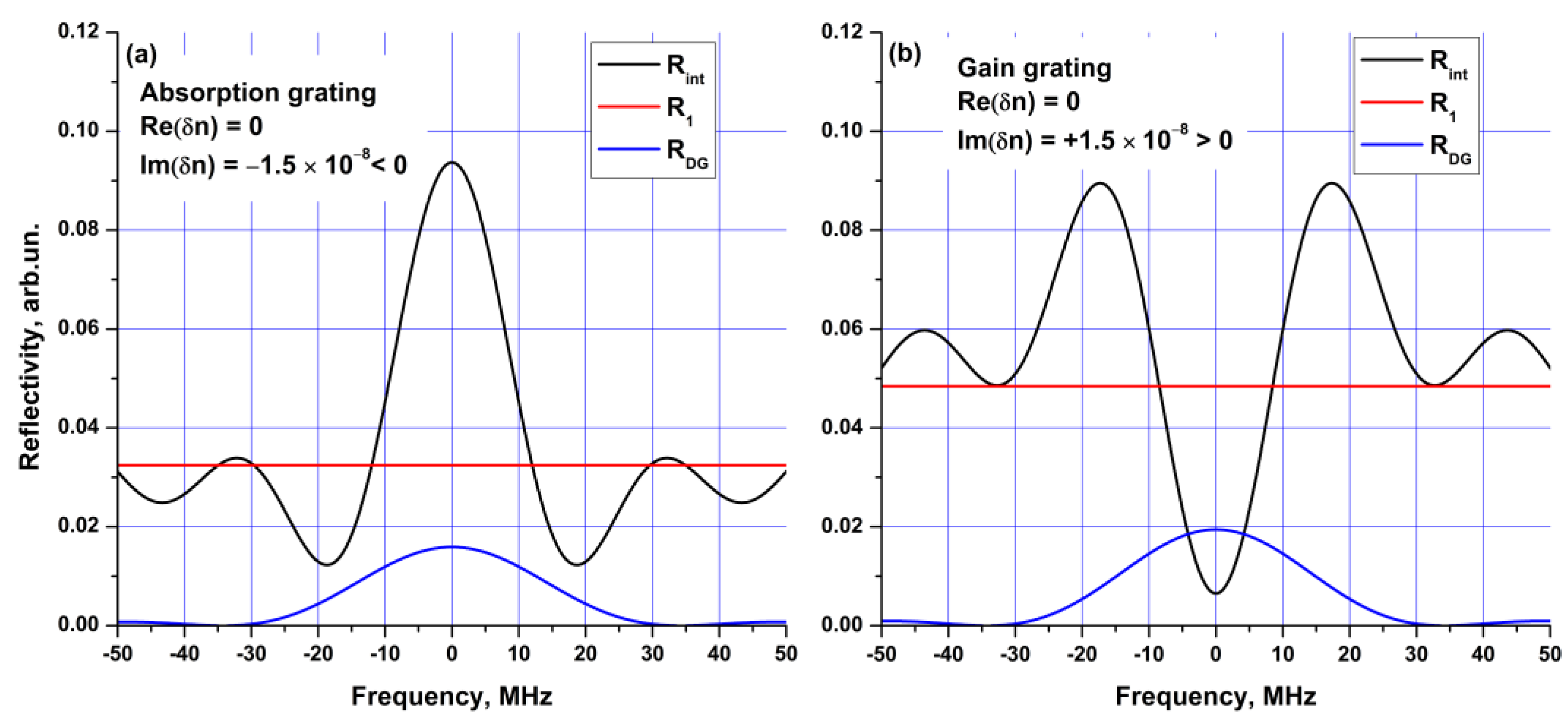
We will now consider the impact of the medium type on the reflectance of a DPG. For simplicity, let us consider the situation when the medium has a small absorption/gain coefficient |exp(2gL)−1| << 1, i.e., |gL| << 1, and the cavity mirror has low reflectance (R1 = 4%). First, we consider only the contribution of the amplitude DPGs, i.e., Re δ n ˜ = 0 . The reflection spectra for the absorption ( I m δ n ˜ > 0 ) and gain ( I m δ n ˜ < 0 ) DPGs are presented in Figure 2a,b, respectively. Central frequency corresponds to the radiation that formed the DPG. In fact, the active FPR reflection spectra (black curves) are results of interference between waves reflected from the DPG (blue curves) and the cavity mirror (red straight lines). This fact manifests itself in the high-frequency modulation of the reflection spectrum depending on the passive fiber length lpf (inter-mirror distance in the active FPR). Despite the fact that the reflection spectra of the DPGs themselves do not depend on the sign of the imaginary part, the active FPR reflection spectrum changes significantly: a peak and a dip at the central frequency are observed in the absorbing and gain media, respectively. The appearance of the active FPR reflection maximum at the optical frequency of the recording radiation causes the stabilization of the radiation frequency for the absorbing DPG. The gain DPG leads to the appearance of peaks of greater amplitude at frequencies different from the central one, resulting in the generation of new frequencies.
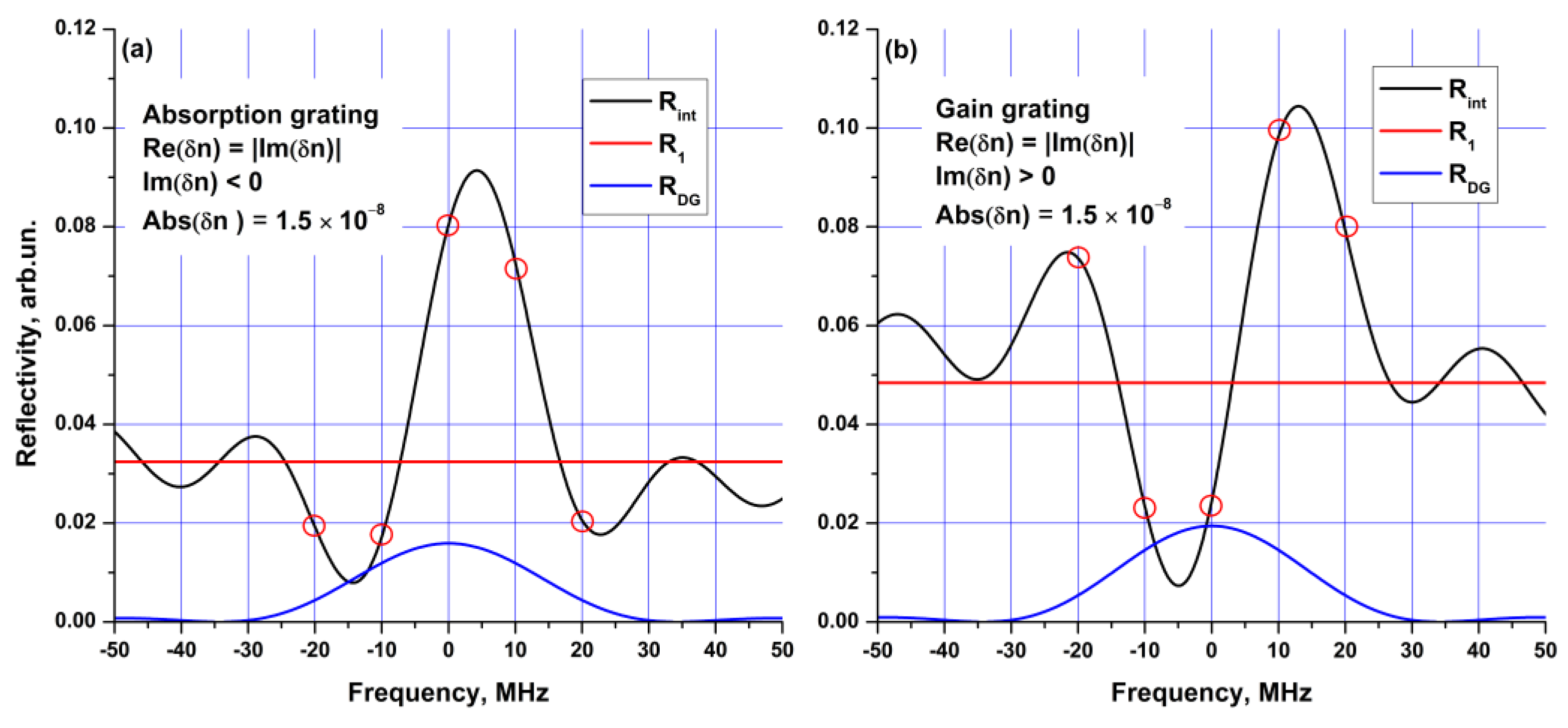
It should be noted that active FPR reflection spectra are symmetric. This means that, in the case of the gain DPG, the maximum quality factor of the cavity is achieved simultaneously for two symmetric longitudinal modes. This uncertainty disappears if the phase DPG is taken into account. For simplicity, let us suppose that the phase and amplitude DPGs have equal impact, i.e., Re δ n ˜ = I m δ n ˜ . Figure 3 shows spectra similar to those in Figure 2, but with the phase DPG taken into consideration. In both cases, the reflection spectra are asymmetric, and the reflection maximum is reached only for a single longitudinal mode. It should be also noted that only frequencies corresponding to the laser cavity longitudinal modes can go into lasing (see the red circles in Figure 3b indicating the positions of the modes in a cavity with a free spectral range set to 10 MHz). For the gain DPG, the gain-to-loss ratio for the central longitudinal mode decreases after recording the DPG, and the mode eventually switches to another one. The relaxation oscillations in a laser provide a good illustration of this process: when the lasing mode fades, the DPGs can still remain in the active medium, since their long lifetime is determined by the lifetime of the excited state of the dopant ions and can exceed the lifetime of generating longitudinal modes by several orders of magnitude. DPGs formed by the spectral filter exist in the laser for some time, even when the mode forming the gratings stops lasing. The DPG selectively changes the quality factor of the cavity. In this way, the longitudinal modes different from the lasing one can become more energetically preferable. This means that the following modes will still be reflected by the active FPR in accordance with the spectrum shown in Figure 3b, leading to mode-hopping in the lasing frequency; then, the described process can repeat. Thus, a new mode with a slightly different generation frequency occurs. Due to the spectral shape of the active FPR forming between the DPG and the laser cavity mirror, the frequency hops have fixed values. If this process repeats many times, a wavelength self-sweeping (WLSS) effect can be observed. Moreover, under certain conditions, the WLSS effect can also be observed for the absorption DPG (see, for example, [42]). In other words, the phase DPGs, even in combination with absorption ones, in some cases, can result in regular frequency hopping. It should be noted that mode-hopping is also observed in SLM lasers. Usually, this process can be associated with temperature and mechanical fluctuations in the laser parameters. As a result, the mode hopping in SLM lasers has a random characteristic [43]. An important difference between mode hopping in WLSS and in SLM lasers is the regular and chaotic optical frequency dynamics in former and latter cases, respectively.
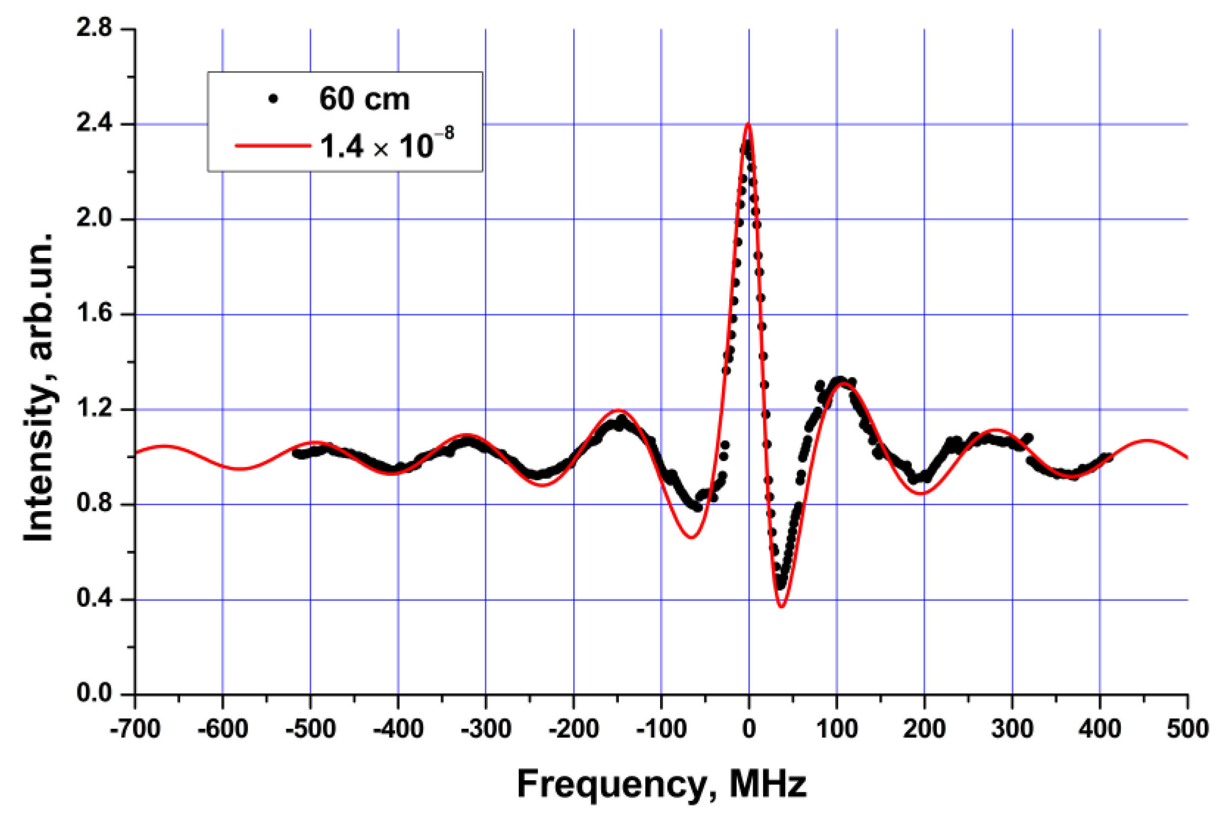
In the analysis above, only the relationship between the phase and amplitude components of DPG is varied. In fact, this relation is determined by the properties of the medium in accordance with the Kramers-Kronig relations. For some active fibers, the contribution of phase DPG has already been measured. Complex measurements for an Er-doped medium [34,35,44] showed that the phase DPG was close to zero near a wavelength of ~1530 nm. The contribution of the phase DPG in relation to the amplitude one increases in the long- and short-wavelength regions of Er-doped fiber lasers. For example, the ratio between the phase and amplitude DPGs increases to >~0.5 at wavelengths of 1560–1570 nm. For the Yb- [45] and Bi-doped [46] fibers, this value is ~1.5, indicating that the contribution of the phase DPG is very significant for these media. As mentioned above, experimental studies have mostly focused on the DPGs formed by external radiation. However, of special scientific interest is the analysis of the DPGs formed directly during the lasing process in DPG-based lasers. The reflection spectra of DPGs for Yb-doped lasers with WLSS were numerically modelled in [47,48,49]. In particular, it was shown that such DPGs can have reflectance of more than 80%; however, such large values have not been experimentally confirmed. The reflection spectrum of the active FPR formed directly in a WLSS laser was measured in [41]. In order to quickly measure the DPG reflection, a three-port acousto-optic modulator (AOM) was inserted into the laser cavity. In the «off» state of the AOM the laser cavity was closed, and the laser operated in the WLSS regime. When the AOM was switched on, the laser cavity was opened, and the FPR reflection spectrum was measured (see Figure 4) with a tunable single-frequency probe laser. As a result of these measurements the amplitude of the complex DPG in the a Yb-doped WLSS laser was defined to be about δ n ˜   ~   1.5 10 8 , which corresponds to the DPG reflectance of ~0.1%. The measured DPG reflection bandwidth ~50 MHz proves the high selectivity of the DPGs.
In summary, this section showed that DPGs in the active fiber consist of two components: amplitude and phase ones. In turn, the amplitude DPGs can be either absorption or gain types. If such dynamic structures are inserted into a laser cavity, the former contributes to the wavelength stabilization, while the latter leads to unstable frequency hops. In this case, the phase component introduces an asymmetry into the reflection spectrum of the DPG, which dictates the nature of the frequency hops. A periodic sequence of such hops appears as the WLSS effect. The following sections are devoted to experimental studies of lasers based on DPGs.

3. Lasers with Generation of Stabilized SLM Radiation

In the theoretical part of this paper, it was demonstrated that standing wave radiation forms absorption DPGs in absorbing active fibers. Such DPGs contribute to spectral selection and SLM stabilization. In contrast, the gain DPG formed in amplifying fibers causes instability of the SLM generation. It can be concluded that the absorption DPG can be used to obtain stable SLM lasing. This section is dedicated to fiber lasers in which the absorption DPGs formed in the doped fibers are used to stabilize lasing frequency of the narrowband radiation. It should be noted that most papers concern Er-doped fiber (EDF) lasers due to the great importance of the wavelength range near 1550 nm for sensing and telecommunication tasks [50,51,52]. However, all approaches developed in EDF lasers were also implemented in fiber lasers based on other popular active fibers (Yb- [53,54] and Tm-doped [55,56]). It should be also noted that this section mainly presents the results on continuous-wave (CW) SLM generation. Standard techniques such as gain-switching, Q-switching, and pulse shaping using external amplitude modulators can be used to obtain pulsed generation (see, for example, [57,58]).

3.1. Approaches for the Gain DPG Suppression

One of the main problems in the experimental implementation of the approach mentioned above relates to the necessity to simultaneously suppress and create the standing wave in the amplifying and absorbing media, respectively. It also means that the laser should contain two main elements: the gain and the absorbing active fibers. The DPG is significantly suppressed in cases of standing wave intensity pattern blurring. This process can be achieved in two ways: (1) by crossing polarization states of two counterpropagating waves in a linear cavity configuration [50,53,54,59] or (2) by suppressing standing wave in a unidirectional ring cavity configuration [60,61,62].
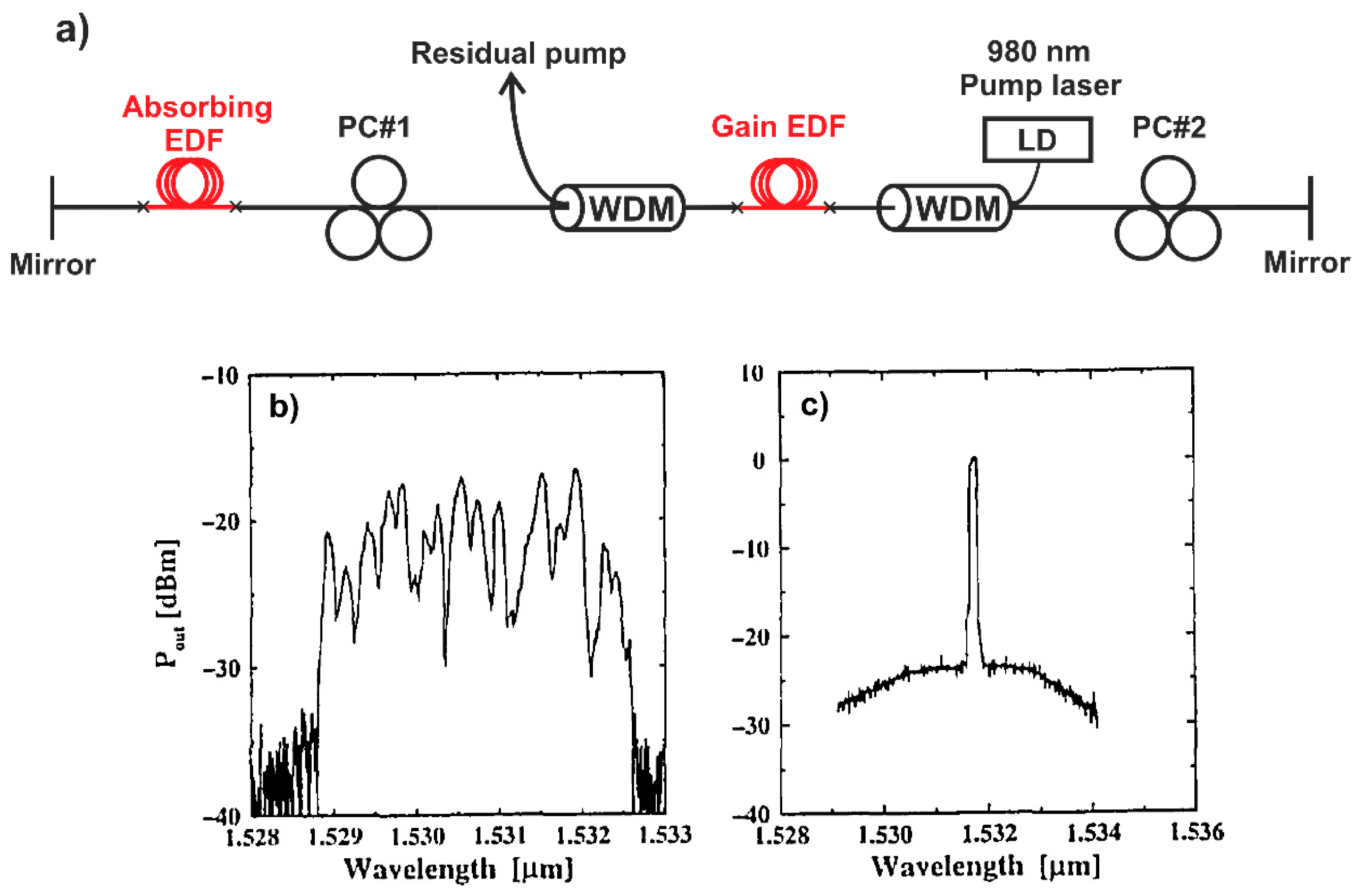
The former approach was described in [59] and experimentally demonstrated in an EDF laser with a linear cavity [50]. Standing wave blurring in an EDF amplifier was achieved in [50] with proper adjustment of two polarization controllers (PCs); see Figure 5a. Another EDF with a length of 32 cm played a role of a saturable absorber (SA) to produce a dynamic narrowband spectral filter. It should be noted that in several papers, the term SA is used for the absorption DPG. However, conventional SAs (such as SESAM, graphene and so on) are usually used for the purpose of pulse generation instead of SLM lasing. An EDF laser operating without any additional selectors generated at a wavelength of 1532 nm which is defined by the gain spectrum maximum. In this paper, the authors achieved SLM lasing with a linewidth estimated to be ~20 kHz; see Figure 5c. Periods of stable SLM operation of units of minutes were separated with hops to the neighboring longitudinal modes. The authors also reported on the broadband spectrum generation with bandwidths of several nm when the SA was removed; see Figure 5c. In previous papers, a hysteretic behavior of the output power as a function of the pump was noted. This behavior was described further in later papers devoted to SLM lasers. The output power hysteresis was studied in detail in [51,52], and different schemes where the hysteresis manifests itself the most clearly were proposed in [55,56]. It was determined that this output power behavior relates directly to the absorption saturation in the SA [51,52]. The polarization suppression of the standing wave in the gain medium was also demonstrated in Yb-doped lasers. By proper adjustment of the PC in the linear part of the laser cavity, SLM lasing with output powers of up to 18 and 14 mW was obtained at wavelengths of 1064 and 1083 nm in [54] and [53], respectively. It should be noted that this approach is used rarely due to the necessity of fine adjustment of the PCs.
An approach based on the ring unidirectional design of the amplifying part is more common. The unidirectional suppression of the standing wave was first proposed in [60]. Unidirectional generation was achieved by placing an optical isolator in the amplifying ring part of the laser cavity (Figure 6). The standing wave formed in the absorbing EDF due to the reflection from the FBG in the linear part of the cavity. It should be noted that in several papers, the laser cavity with both ring and linear parts is referred to as the sigma cavity (for example, [63]). During the experiments, the properties were studied of the output radiation for absorption fiber lengths varying from 0.2 to 6 m. The authors achieved SLM lasing for all configurations and noted that the generation stability depends on the SA length. The best stability of the SLM operation with a typical duration of the wavelength stabilization of 2 h was observed with an absorbing fiber length of 4 m. The coherent properties of the radiation were studied carefully for this configuration: linewidth and relative intensity noise (RIN) were measured to be ~1 kHz and −77 dB/Hz, respectively.
Furthermore, the optical fiber circulator, which eliminates the waves propagating in the reversed direction, is perfect for the simultaneous formation/suppression of the standing waves in the linear/ring part of the cavity. A setup based on a circulator was first proposed in [61] (Figure 7). An FBG which is tunable by stretching in the wavelength range of 1522–1562 nm, placed in the linear part of the cavity, was used here as a coarse spectral selector. SLM lasing with a linewidth of 0.75 kHz was demonstrated.
Thus, there is a tendency to provide standing wave suppression in the amplifying medium in order to obtain stable SLM operation and to suppress the SHB effect in the gain medium, leading to instability of the generation wavelength. For this purpose, there are two main approaches: (1) blurring the standing wave, for example, by achieving crossed polarization states of two counterpropagating waves in a linear cavity configuration; or (2) achieving unidirectional generation in a ring cavity configuration. It should be noted that the latter approach is more popular and easier to implement.
However, several works have discussed the impacts of gain and absorption DPGs. For example, a paper [64] concerning an EDF laser with a linear cavity demonstrated that it may be possible to achieve few-mode lasing with different impacts of each longitudinal mode depending on the pump power and relative positions of the gain and absorbing media. It was shown that dual- and triple-frequency lasing occurred at low and high pump powers, respectively, if the absorption/gain DPG formed exactly at the end/in the middle of the cavity, respectively. It is also possible to consider situations when amplification and absorption take place simultaneously in a single piece of an active fiber. In fact, the output part of the fiber is practically not pumped and works as an absorbing medium, when a sufficiently long peace of active fiber has a high pump absorption. It was demonstrated in [65] that it is also possible to obtain SLM lasing in this case despite the presence of a standing wave in the gain medium. This situation can be mainly realized if the gain part is short compared to the absorbing one. In particular, the authors noted that for a sufficiently short active fiber (~2 m), the SLM generation stability is low due to small length of the absorbing part. The same approach with an unpumped active medium was used to create an SLM laser with the gain modulation in [66]. In this case, SLM lasing with linewidths of less than 6 kHz and 7.5 MHz was obtained in CW and pulsed regimes, respectively. An unpumped active fiber can also be placed into a ring cavity with bidirectional propagation of the radiation [62]. The authors obtained the stable SLM lasing with a linewidth of 7.4 kHz due to small length of the gain part in this configuration. Thus, several works proved that SLM operation can be obtained even in the presence of gain DPG. However, it is necessary to increase significantly the contribution of the absorption DPG in this case.

3.2. Approaches for Effective Formation of the Absorption DPG

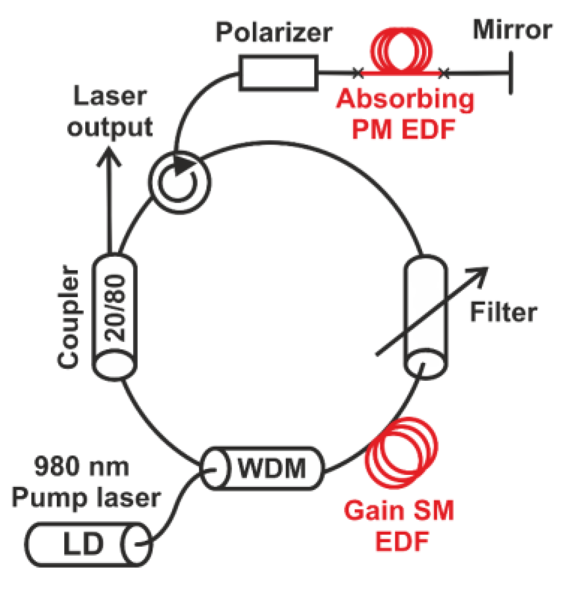
The same polarization states of the counterpropagating waves in the linear part of the cavity are necessary for the efficient formation of the absorption DPG. This can be achieved, for example, by inserting a PC into the laser cavity and properly adjusting the PC. However, the lasing in such schemes is extremely sensitive to the external impacts. The robust solution is to use polarization maintaining (PM) fibers and polarizing elements (Figure 8). This approach was first used in [67]. In this work the standing wave formed in the linear part of the cavity due to the reflection from a broadband mirror based on an aluminum film. An additional filter with a spectral bandwidth of 1 nm tunable in the wavelength range from 1530 to 1570 nm was placed in the ring part of the cavity for coarse spectral selection. The authors compared the stability of the SLM operation for the PM and conventional non-PM fibers and reported about better stability in the former case.
Additionally, the dependence of the SLM generation stability on the SA length and lasing wavelength was studied in [67]. The influence of the SA length (0.5–5.5 m) on the temporal stability of the SLM operation was noted. The best generation stability (more than 2 h) was observed for the SA length of 2 m. A similar dependence on SA length was also reported in [60]. However, it should be noted that the optimal length with the highest stability of the SLM operation depends on the pump power. For the optimal configuration (2 m, 1530 nm), the coherent properties of the radiation were as follows: linewidth and RIN were measured to be ~1.5 kHz and −74 dB/Hz, respectively. The absorption coefficient in SAs depends on lasing wavelength. In particular, the lasing stability decreases with tuning to sufficiently long lasing wavelengths (>1535 nm), as a result of the DPG formation efficiency reduction. In this case, it is preferable to use fibers with higher dopant concentrations. In this case, it is preferable to use fibers with higher dopant concentrations. This issue was experimentally verified in [63], where the lasing behavior for two types of fibers with different absorption coefficients was studied. For a fiber with lower doping level the dual-frequency operation was observed, while the stable SLM lasing was observed with the other one. Additionally, the generation properties for absorbing fiber lengths of 1.2 and 5 m were compared in a paper dedicated to the Yb-doped SLM laser [54]. The generation was more stable at larger length of the absorbing fiber.
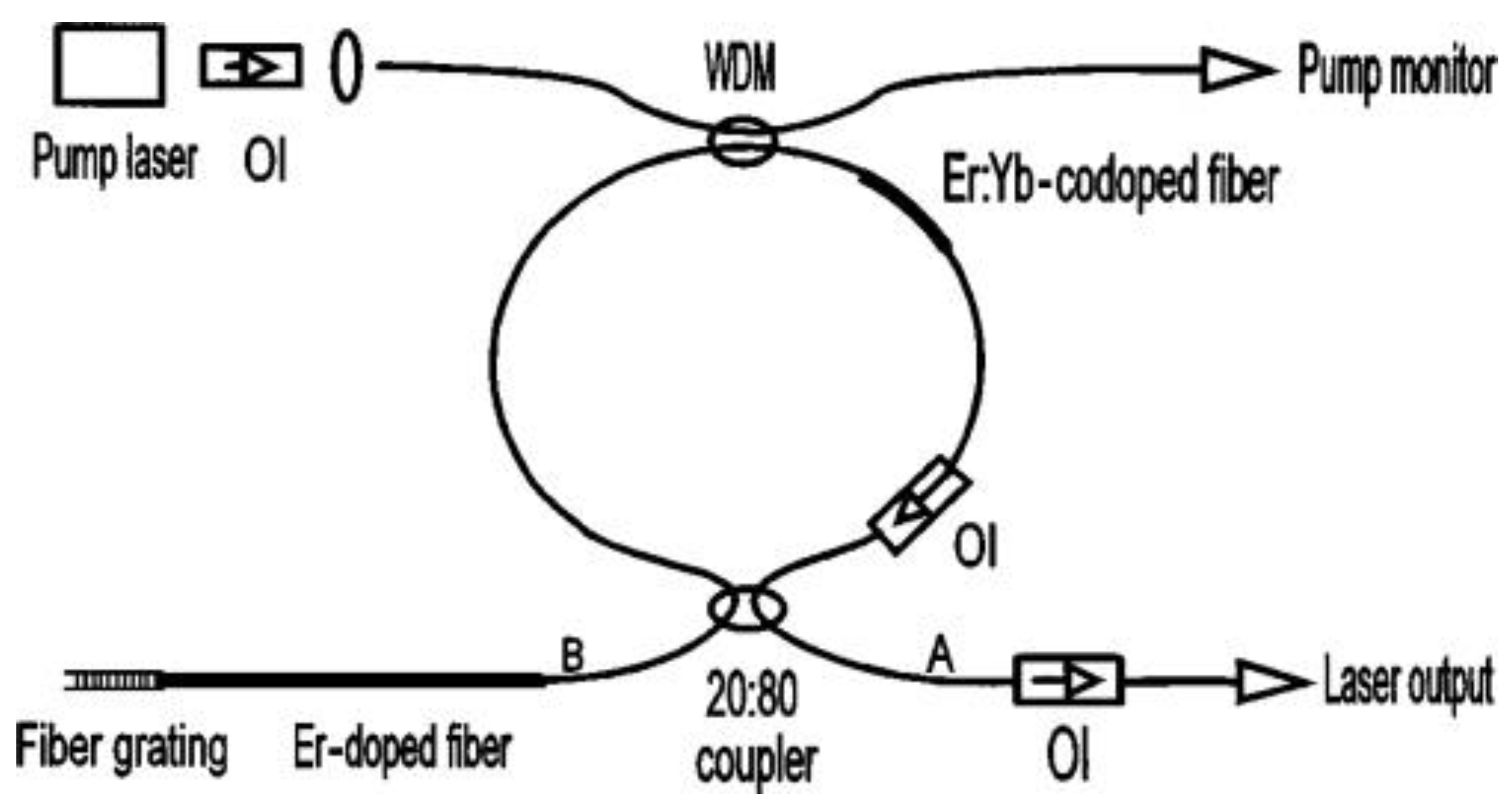
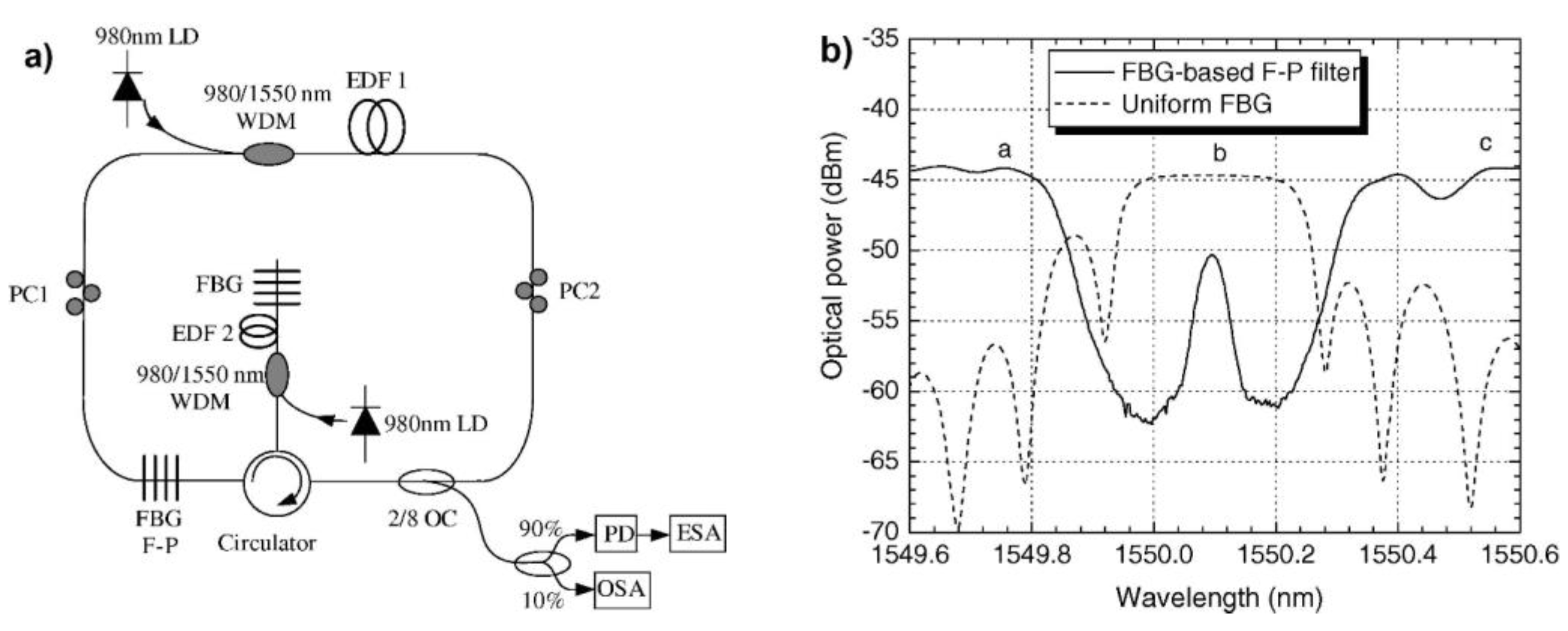
The impact of the absorbing fiber parameters on lasing was also studied in other papers. For example, a method for the control of the absorption in the SA with additional pumping was proposed in [68]. The authors used three types of selectors: (1) uniform FBG placed in the linear part of the cavity, (2) Fabry-Perot interferometer based on two FBGs placed in the ring part of the cavity, and (3) absorption DPG pumped by additional pump source in the linear part of the cavity (Figure 9a). The reflection spectrum for the first and transmission spectrum for the second filter are presented in Figure 9b. The proper adjustment of wavelength for each of these filters led to stable SLM lasing without frequency hops. Similar control of the absorbing DPG formation efficiency by insertion of an additional pumping was also studied in a Tm-doped laser with lasing at the wavelength of 1720 nm [69]. A flexible approach to control the absorption DPG parameters with the use of an additional pumping made it possible to demonstrate SLM generation with linewidth, RIN, and output power of 3.3 kHz, −112 dB/Hz, and more than 2.5 W, respectively.
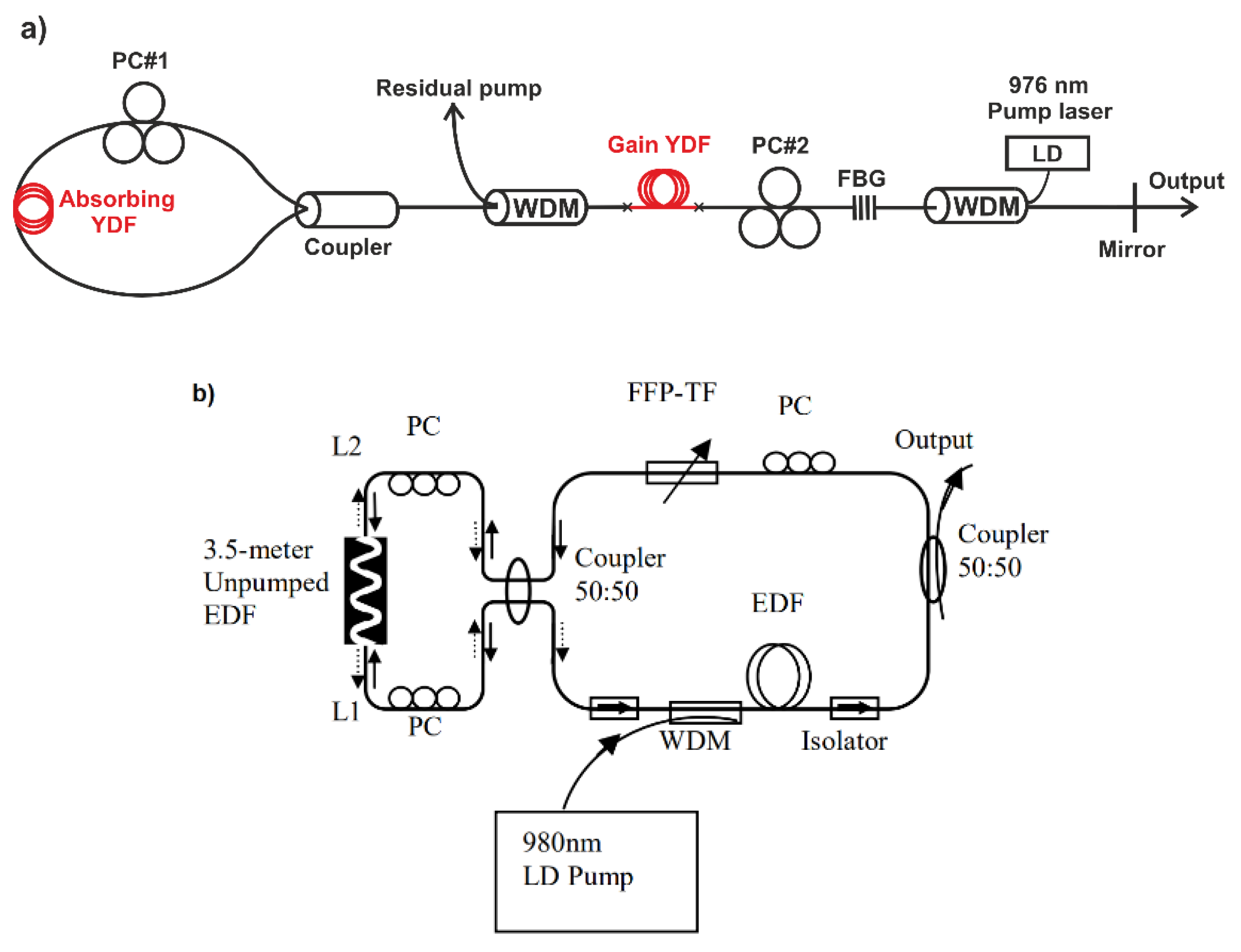
It should be noted that a standing wave can form not only in the linear part of a sigma-cavity, but also inside a fiber coupler-based Sagnac mirror (SM). Such an implementation of a dynamic filter was first described in [51] concerning a laser with a linear cavity (Figure 10a). Later, a similar SM was used in a ring fiber laser [70] (Figure 10b). In this case, an SLM lasing with a linewidth of 0.7 kHz and maximum output power of ~10 mW was obtained. In the same work, a theoretical description of the SM operation was presented. Such schemes also require adjustment of the polarization states of the two counterpropagating waves using PC. Similar schemes were also demonstrated in Yb- [71] and Tm-doped [72] fiber lasers.
In all the papers described above, the DPG that formed in the SA was used as a narrowband filter providing SLM selection. However, to improve the SLM generation stability, some additional selectors based on non-dynamic filters are typically placed inside the laser cavity. It seems to be the most efficient to use filters with spectral widths that are comparable to the free spectral range (FSR) of the laser cavity (units or tens of MHz are typical for fiber lasers). For example, in the paper mentioned above [68], a reduction of the rate of irregular mode hops was achieved mostly by additional spectral selection with the aforementioned intracavity Fabry-Perot interferometer. Similar interferometers based on a set of the FBGs were used for the spectral selection in Yb-doped lasers in [54,73]. Additional filtration can also be achieved using other types of interferometers. For example, a Mach-Zehnder interferometer with FSR of 49 MHz was placed in the linear part of EDF laser [74]. This approach made it possible to increase the output power up to 867 mW. More complicated spectral selection based on the Vernier effect in the set of nested cavities was demonstrated in [75].
Moreover, wavelength tuning of additional intracavity filters enables control of the lasing wavelength. Tunable filters can be based with FBGs [61], Fabry-Perot interferometers [70], or thin films [67,71]. Such filters can provide wavelength tuning of the SLM generation in a range of up to 60 nm [71]. Sweeping operation can be achieved as well by fast tuning the filter wavelength. The best stability of the output parameters was observed in [70] with a filter tuning rate of ~20 Hz. It should be noted that fast tuning in a relatively small spectral range can be also obtained by the RI control of some intracavity elements. For this purpose, in [76], a phase element based on lithium niobate was added to the cavity to provide SLM lasing with the sweeping rate up to 1 kHz.
Thus, we can conclude that the absorption DPG plays a role of an adaptive narrow-band filter, which makes it possible to fix laser generation to single longitudinal mode. To improve the operation efficiency of such a filter, one should do the following: (1) make a rough spectral preselection using non-dynamics filters; (2) form a standing wave in the SA in a linear or ring configurations with matched polarization states of counterpropagating waves; (3) provide length-efficient absorption of lasing radiation in the SA. In these cases, it is possible to obtain stable SLM generation without hops between longitudinal modes during tens of minutes.

3.3. Summary

Table 1 presents a comparison of the characteristics of SLM lasers based on filters with SAs. Generally, it can be noted that the scheme with an adaptive filter can provide SLM generation with a linewidth not exceeding 1 kHz [61,76], output powers from units of milliwatts to units of watts [69], and with the possibility of wavelength tuning in a wide range of up to 60 nm [71]. For SLM radiation, special attention is paid to the noise characteristics, such as the RIN parameter. It was proved that in such systems, the RIN value can be reduced to −112 dB/Hz [69], which is relatively good compared to other types of SLM fiber lasers. It was also found that pump source noises also affect laser generation properties. For example, the noise characteristics of the output radiation of an Yb-doped SLM sigma-cavity fiber at pump wavelengths of 976 and 1018 nm were compared in [77]. It was noted that the generation noises are higher in the former case (which is few-mode) compared to the latter one. As mentioned above, most papers in this field of science are dedicated to Er-, Yb-, and Tm-doped lasers. To our best knowledge, there do not exist papers concerning SLM lasers with DPG based on Ho-, Bi-, and Nd-doped fibers. This situation for Nd-doped fibers can relate to very low signal absorption at lasing wavelength.

4. Fiber Lasers with Wavelength Self-Sweeping

In the previous section, it was demonstrated that SLM generation requires a significant contribution from the absorption DPG. In this section, we consider the opposite situation, i.e., with gain DPG. As shown in Section 2, this type of DPG results in the WLSS effect. Such laser wavelength dynamics were first mentioned at the dawn of laser physics in solid-state lasers [82]. However, the effect was considered parasitic, and attempts were made to suppress it by erasing the standing wave. To this end, the approaches mentioned in Section 3.1 based on polarization control or unidirectional generation in a ring configuration can be used. Some other approaches for the suppression of DPG formation by standing wave were proposed as well. For example, to suppress DPG formation, a pair of phase modulators operating out of phase was inserted into a laser cavity in [83]. Regular laser wavelength instability (it had not yet been defined as the WLSS effect) in fiber lasers was first demonstrated in [84] in a ring unidirectional laser with the coarse spectral selection provided by a long-period grating (LPG). The authors reported on so-called “spectral oscillations”, observed for various LPGs in the wavelength region of 1050–1100 nm. It could appear that the use of a ring unidirectional scheme with an optical isolator would effectively suppress the formation of standing waves in the gain medium. Consequently, one would expect the absence of a gain DPG in the active medium. However, later in [85], the same group established the presence of a weak feedback from the output fiber connector in exactly the same laser scheme. This weak reflection caused the formation of a backward-reflected wave and, consequently, the formation of a DPG in the gain medium. In this scheme, the authors observed a periodic and regular lasing wavelength in a range of 1086–1089 nm, determined by the spectral properties of the intracavity spectral filter. In other words, the “spectral oscillations” observed in [84] were the WLSS effect. Thus, the importance of the standing wave for the WLSS effect was immediately noted in the very first works.

4.1. Approaches for the Effective Formation of Gain DPG in WLSS Lasers

An effectively formed gain DPG is a necessary condition for the WLSS effect. General approaches for the effective formation of absorption DPGs, as described in Section 3.2, can also be used for gain ones. It is necessary to match the polarization states of two counterpropagating waves. A PC should be added into the cavity in the case of conventional single-mode fibers (SMFs) [86,87,88,89,90,91,92]. However, in this case, the fine tuning of the PC is required. Also, the lasing in such schemes is sensitive to external mechanical perturbations. In addition, it seems problematic to optimize the scheme, since each configuration of the elements requires unique PC adjustments. An alternative which is more stable under external perturbations is the use of the elements based on PM fibers [45,93,94,95,96,97,98,99]. In this case, only one polarization mode which forms the DPGs is supported by the cavity. However, in some cases the WLSS effect can simultaneously take place for two polarization modes. For example, the parameters of non-PM cavity were matched in [92] in such a way that a simultaneous WLSS of two laser lines with different polarizations and frequencies was observed. It should be noted that in other works devoted to the WLSS lasers based on non-PM fibers the polarization analysis of lasing radiation was not performed.
Additionally, DPG modulation depth and length are essential to obtain high spectral selectivity and reflectance. These parameters are mostly determined by the product of the intensities of two counterpropagating waves forming the interference pattern inside the gain fiber. However, it should be noted that the product is nearly constant along the gain fiber since the waves are amplified in a similar way (one can consider exponential growth, for simplicity). As a result, in the most cases the DPG length is equal to the gain fiber length. As a rule of thumb, relatively long doped fibers ranging from units [93] to several tens of meters [100]) are usually required to observe the WLSS effect. The DPG modulation depth, as mentioned in Section 2, depends not only on the wave intensities product, but also on the gain fiber properties (for example, on the saturation power). It is also expected that the properties of the gain DPG, and hence, the WLSS effect, must be affected by the active dopant concentration, similarly to the case of the absorbing fibers. However, systematic research in this area has not been carried out yet.
The simplest way to form a standing wave is the use of a Fabry-Perot cavity. That is why most works dedicated to the WLSS effect have focused on Fabry-Perot cavities [45,46,86,87,89,97,98,99,100,101,102], while only a small number have been devoted to the WLSS effect in ring configurations [84,103,104,105,106]. WLSS lasers based on the Fabry-Perot cavity are very similar to standard fiber lasers. Moreover, the WLSS was observed even in classical fiber laser schemes (see, for example, [107]), where its presence was not expected. The rather late discovery (only ~10 years ago) of the WLSS in fiber lasers can relate to the difficulty of its experimental analysis. There exist several reasons for this. First, various narrow-band spectral filters are typically added to the cavity for the wavelength selection. It is easy to understand that even in the case of WLSS operation, the WLSS range (difference between maximum and minimum wavelengths reached during a single sweep) cannot exceed a bandwidth of the narrowest spectral laser selector. The most common filter for fiber lasers is an FBG with a bandwidth of the reflection spectrum of ~100–1000 pm. Second, typical equipment used for the spectral analysis of fiber laser radiation is based on diffraction gratings, which have a relatively low spectral resolution and are usually suitable only for the analysis of time-stable optical spectra.
It became possible to obtain and prove the WLSS operation by using broadband selectors and reflectors. In this case a relatively large WLSS range can be achieved. Such reflectors include right-angle cleaved fiber ends with Fresnel reflection (FR) [108] or an SM [86]. The first significant WLSS range of ~7 nm was obtained in a linear scheme with two mirrors formed right-angle cleaved fiber ends [108]. In fact, the laser consisted solely of 11.5-m-long GTWave Yb-doped fiber and a pump source (Figure 11a). In this laser a gradual movement of the lasing line from 1080 to 1087 nm with an instantaneous jump to the initial position was observed with a conventional optical spectrum analyzer (Figure 11b). The authors noted the dependency of the WLSS range and rate on the pump power. It is essential to note that the authors associated the observed effect with the mode interference inside the cavity, which, in fact, is a DPG. A similar scheme with cavity mirrors formed by two right-angle cleaved fiber ends was studied in [85,100]. In these works, the laser consisted of a 4.8–5.0-m-long double-cladding Yb-doped fiber, a pump combiner, and a pump source. The WLSS in the wavelength range of 1077–1087 nm was detected with a spectrometer to increase the generated wavelength measurements rate.
The disadvantages of the linear schemes used in [85,100,108] include bidirectional output of generated radiation. In particular, this reduces the unidirectional power for practical applications of such lasers. The bidirectional generation relates to the cavity formed by two mirrors with low reflectance. Unidirectional operation can be obtained by significantly increasing the reflectance for one of the cavity mirrors. For example, in [86], both an FBG and an SM were used as high-reflectance mirror (Figure 12a). The laser active medium was a 2.5-m-long double-cladding Yb-doped fiber pumped by multimode laser diodes through a pump combiner. Using a high-speed laser spectrum analyzer (~300 measurements per second), a regular WLSS near 1066 nm was observed with both types of high-reflectance mirrors (with wide and narrow reflection spectra). In the configuration with the FBG, the WLSS range was relatively small ~100 pm (Figure 12b). However, use of the SM made it possible to increase the WLSS range up to 16 nm (Figure 12b). In addition to the results of [108], the authors found out that the WLSS rate increases with output power and depends on the cavity length. The instantaneous linewidth was estimated to be less than 100 MHz. The observed generation dynamics was associated in these works with the SHB effect, which is also equivalent to gain DPG.
Despite the simplicity of reflectors based on right-angle cleaved fibers, their use as mirrors has a number of drawbacks from a practical point of view. For instance, coupling a WLSS laser output to another fiber scheme with splicing results in the destruction of the output mirror. One of the solutions to this problem, first presented in [86], is to install a fiber coupler and an isolator sequentially (upper part of Figure 12a). This approach leads to an effective decrease of the reflectance of the output mirror. However, in this case, the radiation from the output of the isolator can be spliced with some other fiber schemes and used further, while the second output port of the coupler can be used as a broadband mirror. It should be noted that the linear cavity scheme with the first and second reflectors respectively based on an SM a cleaved fiber is the most studied in the field of the WLSS lasers.
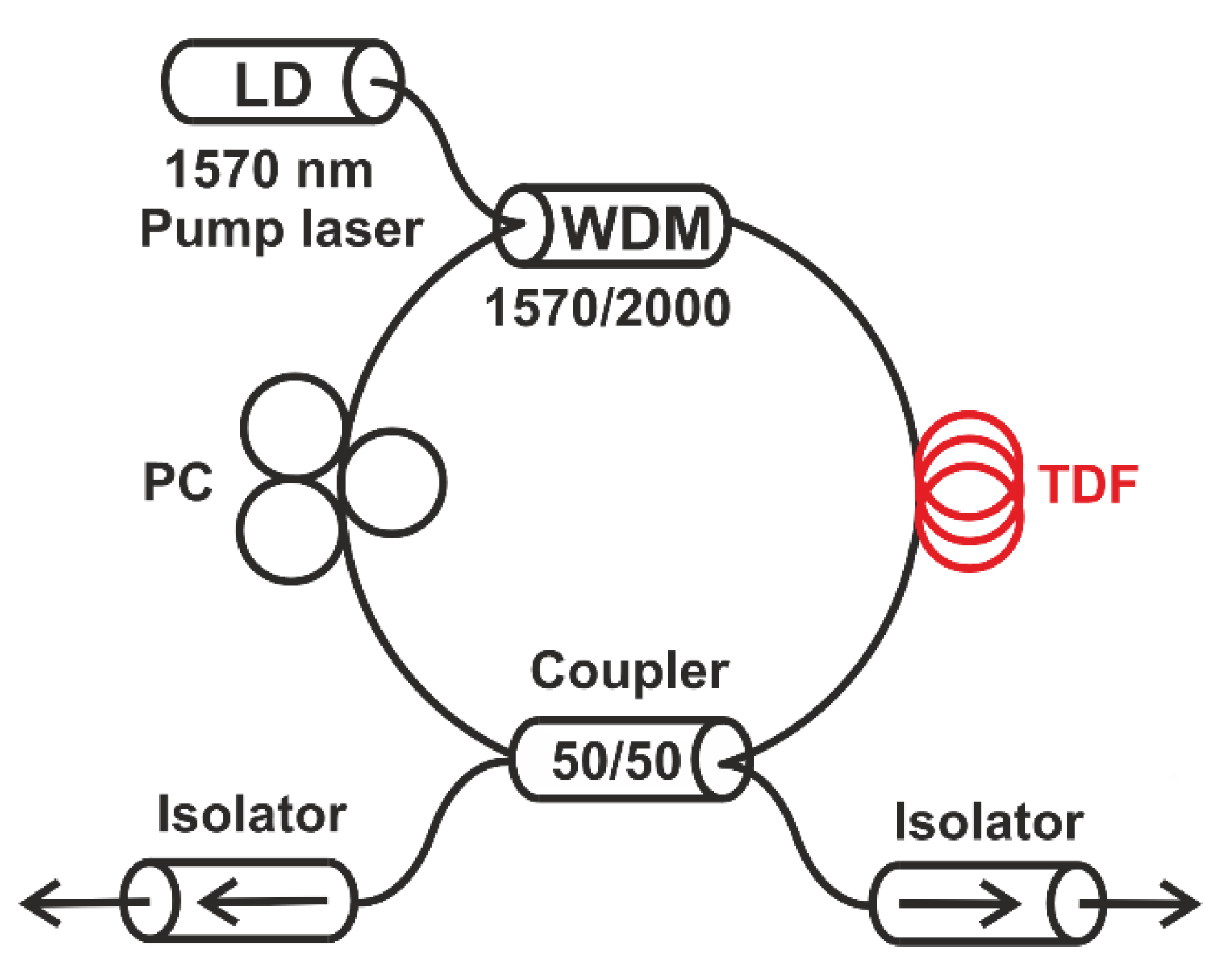
The gain DPG can also be formed in a bidirectional ring cavity (Figure 13). The first results on the WLSS in such a scheme were presented in [105] (a more detailed description in [106]). In the scheme based on a 2.5-m-long Tm-doped fiber the WLSS in the range of up to 14 nm was observed near 1970 nm. The PC had to be properly tuned to achieve the WLSS operation. The advantage of such a scheme is the absence of any reflectors—only a fiber coupler was used here. Later similar schemes were implemented in Yb-doped lasers fibers [88,94,103]. At the same time, in [94] the laser was based on PM fibers.
One more type of scheme where the WLSS can be observed is the sigma cavity, containing both linear and ring parts. The first report on a WLSS in such a scheme was presented in [104]. An important feature of the scheme was that the standing wave formed in the absorbing fiber in the linear part of the cavity (Figure 14a). In this case, the unidirectional generation in the ring part with amplifying fiber provided with a circulator should completely exclude the gain DPG. It should be noted that the sigma cavity is identical to the schemes typically used for the stable SLM operation (see Section 3). Despite this fact instead of the SLM lasing, a regular WLSS in the 5 nm range near the wavelength of 1068 nm was observed in [104]. The WLSS was also investigated in a similar scheme in [109]. In fact, to date, no research has succeeded in resolving this contradiction and determining the conditions under which stable SLM lasing or WLSS is observed. In [42], it was assumed that the phase DPG plays a major role in the WLSS in the sigma cavity. In addition, it can be assumed that a gain DPG can also be formed in the amplifying medium due to the parasitic uncontrolled feedback (as was, for example, in [84,85]). The presence of the gain DPG was also discussed in a recent paper [110] devoted to the discovery of a transition between the lasing regimes with SLM stabilization and WLSS operation observed in an Er-doped sigma-cavity fiber laser via the reduction and elongation of the SA fiber length, correspondingly. However, the exact conditions for stable SLM and WLSS laser operation require further research.
Thus, to observe the WLSS, the effective formation of the gain DPG is required. To achieve this, it is necessary to have the counterpropagating waves matched in intensity and polarization. This condition can be satisfied both in linear and ring configurations. At the same time, relatively large lengths of doped fibers are required for the efficient operation of DPG. As mentioned above, this leads to the dynamics of the mode composition of the radiation. Further we consider approaches to control the sweeping dynamics.

4.2. Approaches for the Mode Dynamics Control

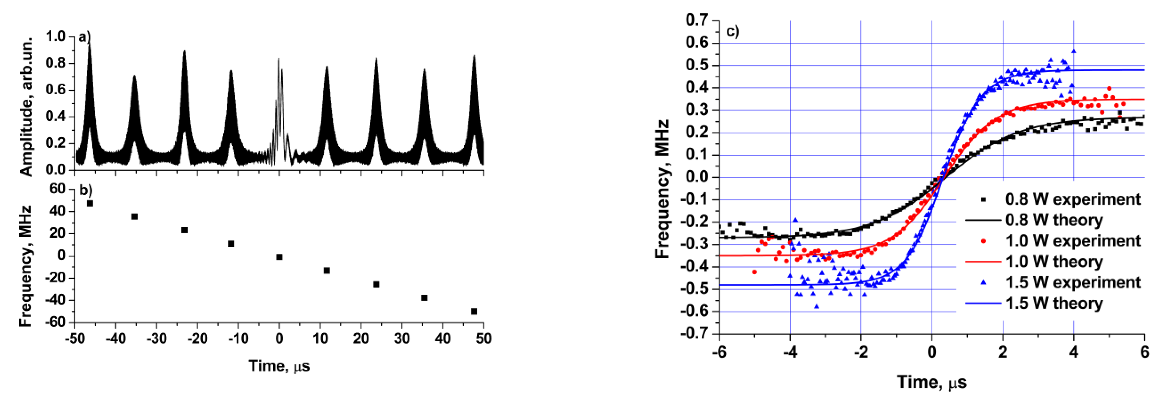
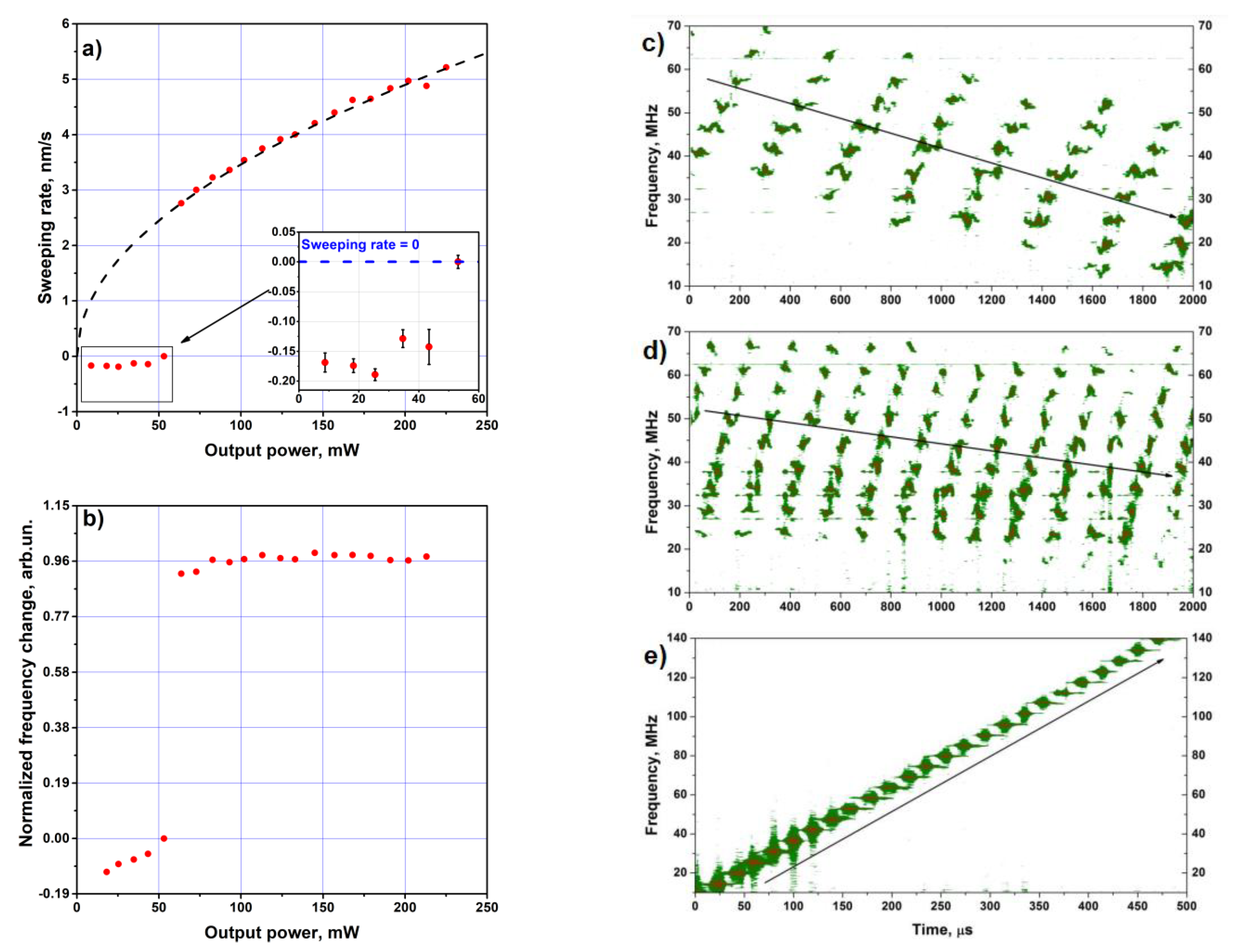
We will first discuss how the longitudinal mode dynamic can manifest itself in addition to the wavelength change. First of all, we will focus on the dynamics of the radiation intensity. In the early works devoted to WLSS the intensity dynamics typically consisted of microsecond self-pulsations, in which some pulses had a high-frequency modulation (see inset to Figure 15a). It was shown in [84] that the self-pulsation repetition rate and the WLSS rate have similar square root dependence on the output power (Figure 15b). So, it was concluded that the wavelength dynamics relate directly to the intensity dynamics. A little later, this assumption was confirmed with direct heterodyne measurements (Figure 16a) in [45], where the radiation of the laser under study was mixed with a reference single-frequency laser source. It was found that from pulse to pulse the optical frequency changes by the value of one or several FSRs only. Moreover, the optical frequency of the radiation changed during a single pulse (the so-called optical frequency chirp) by ~1 MHz (Figure 16b). The frequency chirp can be associated with a change in the average RI of the active medium due to a change in the population during the generation of each pulse. Thus, it was concluded that the WLSS rate is determined both by the intensity dynamics (pulse repetition rate) and by the value of the optical frequency hops between pulses. Many years of research proved that the relatively regular wavelength dynamics manifests itself in the appearance of regularly repeating sequences of pulses each corresponding to a finite set of longitudinal modes. In this case, the number of longitudinal modes in a single pulse, as well as the value of the frequency hops, is mainly determined by the spectral properties of the gain DPG formed by the previously generated modes. In addition, phase DPG are also of significant importance. For example, the simultaneous impact of the amplitude and phase DPGs and their location in relation to the cavity mirrors determines the WLSS direction [42].
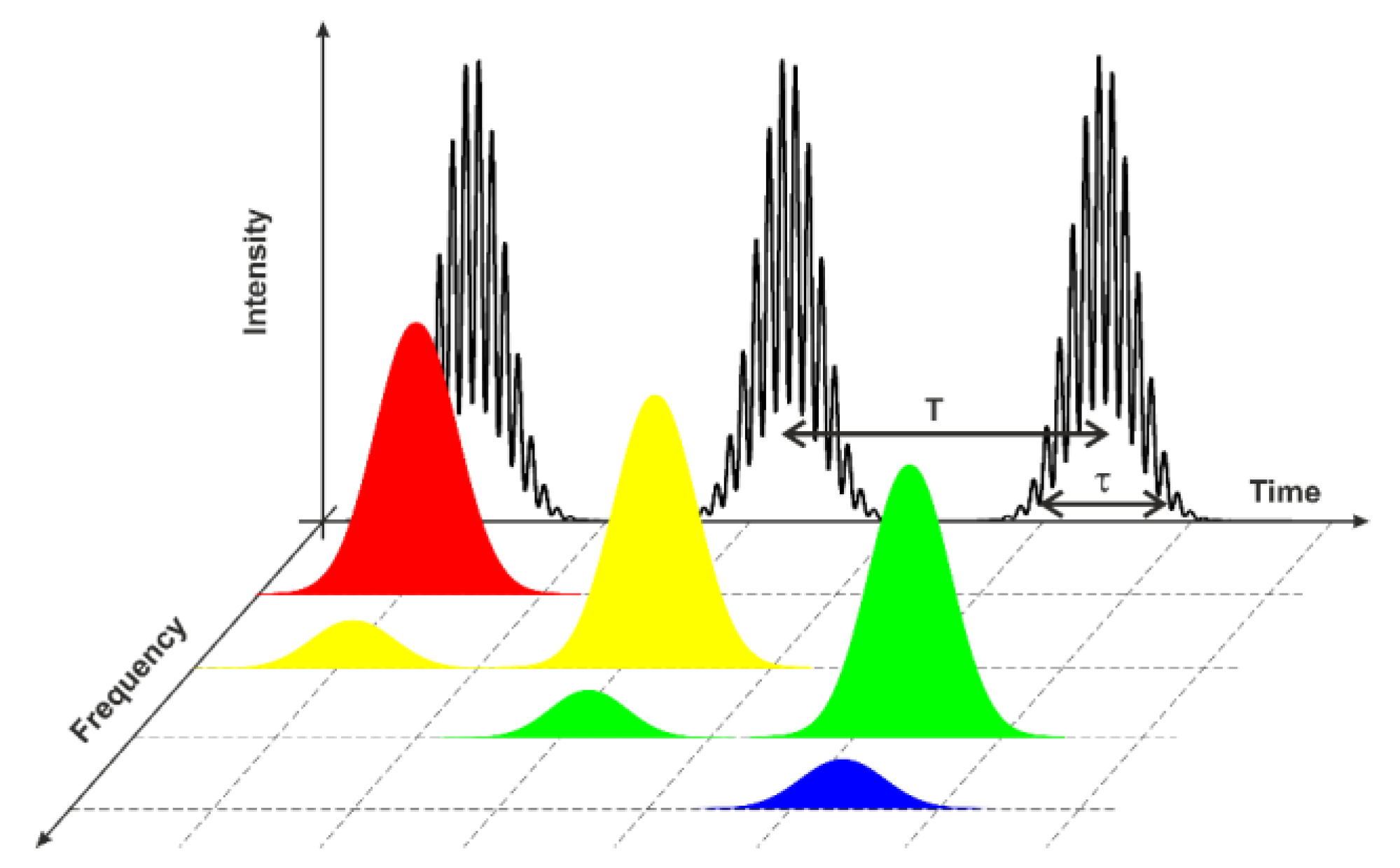
To simplify the description of the mode dynamics in the WLSS lasers, we will further use the term “mode-packet” to denote a set of N modes simultaneously participating in lasing as well as in the formation of DPGs. The mode-packets are characterized with duration t and repetition period T, as well as with a change of they mode composition (Figure 17). Next, let us consider some typical values of these parameters observed in experiments.
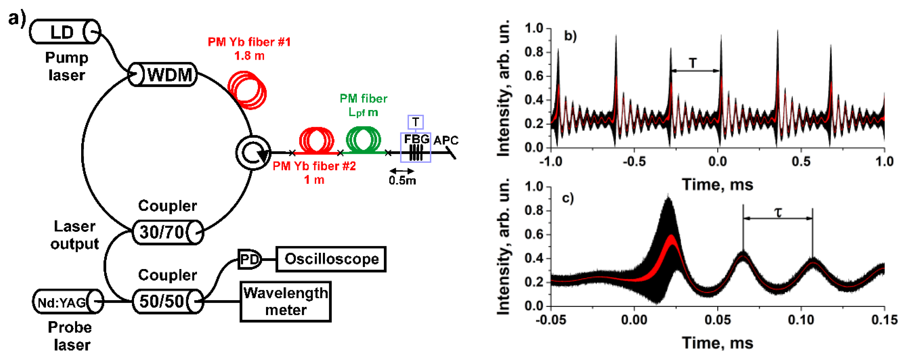
Due to the relatively large length of the DPGs (~1–10 m), they have high spectral selectivity. This means that N typically does not exceed values of several tens. The situation with fine spectral selection is similar to that of SLM generation in lasers with absorption DPGs. It should be noted that the larger the average number of simultaneous oscillating modes N, the smaller the modulation depth of a standing wave due to spatial blurring, which leads to a decrease in the efficiency of the formation of DPGs. In the early literature, only WLSS with simultaneous lasing at several longitudinal modes was observed (see, for example, Figure 15a). It was shown in [44] that N can be controlled by adding a piece of passive fiber into an active FPR forming the laser cavity composed mirror. The passive fiber changes inter mirror spacing as well as the reflection spectrum of the active FPR (see also Section 2). It was also demonstrated that the number of modes oscillating simultaneously in a mode-packet N can be reduced down to one N = 1 (Figure 16b). In this case a mode-packet can be treated as an SLM pulse. This type of the laser dynamics has the greatest importance for practical applications since it corresponds to the generation of single-frequency tunable radiation. To date, the SLM WLSS operation was demonstrated in Yb- [45], Nd- [99], Er- [110], Tm- [95,111], and Bi-doped [46] fiber lasers. Almost all these works estimated the frequency chirp of each mode-packet, which does not typically exceed 1 MHz [45,46,95,99].
The mode composition in WLSS lasers changes from one mode-packet to another according to a frequency which is proportional to the laser FSR. The frequency hops equaled one FSR in all of the SLM WLSS lasers mentioned above. Typical cavity lengths in the fiber lasers were ~5–20 m. These lengths correspond to frequency hops between mode-packets ranging from 20 to 5 MHz. The smallest frequency hop, i.e., ~1 MHz, was demonstrated in a longer (~100 m) Bi-doped fiber laser with smaller FSR [46]. Additionally, a frequency hop of ~1.7 MHz was observed in another long Tm-doped laser [102]. However, frequency hops of several FSRs can be also observed in certain cases (see, for example, [45]). It should be emphasized that a large number of longitudinal modes is sequentially generated in a WLSS laser during a single sweep due to the smallness of the frequency hop value between adjacent mode-packets and large value of the WLSS range. For example, the WLSS range in a Bi-doped laser is ~10 nm (~1.4 THz for a central wavelength of 1460 nm) [46]. Taking into account an individual frequency hop of ~1 MHz, more than a million longitudinal modes were sequentially generated during a single sweep in the laser.
Depending on the active medium and the laser scheme, not only the mode composition of the packets can change, but also their temporal characteristics: lifetime t and repetition period T. The WLSS with the generation of short, bell-shaped pulses, similar to Q-switched lasers [46,86,87,89,92,97,98,99] with t ~ 1–5 μs, is the most well studied. Such WLSS lasers can be called pulsed lasers. The repetition period T is typically several times greater than the pulse duration t in this operation mode. This means that there is practically no lasing during the intervals between the mode-packets. It should be noted that despite the absence of recording radiation between the pulses the neighboring mode packets still can effectively interact through the formed DPGs. The opposite situation with negligible silence intervals between the mode-packets (T ~ t) is possible as well. In other words, a slight admixture of one mode packet presents in the next one. Such operation mode with a significant overlap of the tails of neighboring SLM pulses was observed in an SLM WLSS laser [109]. In this case, the direct interaction of adjacent SLM pulses can occur. It was shown there that phases of neighboring modes are phase locked. In addition, it was suggested that a new mode-packet can be formed from a seed resulting from the four-wave mixing process occurring during the adjacent SLM pulses overlap. Later [42,99,101,104], the WLSS with the time dependence of the intensity looking like a sequence of overlapping rectangular-shaped pulses was demonstrated. In this case t increased up to hundreds of times (t ~ 1–3 ms), and the intervals of silence between the neighboring mode-packets completely disappeared (Figure 18b). Such WLSS lasers can be called CW ones. Their intensity dynamics corresponds to CW generation with short intensity bursts in the transition regions between neighboring mode-packets. Similar CW WLSS was demonstrated both for Yb- [42,104] and Er-doped lasers [101,112]. As mentioned in Section 3.1, such a scheme is similar to the schemes from Section 3.2 used to obtain the stable SLM operation rather than the WLSS one. The authors of [42] suggested that the CW WLSS is provided by a significant contribution of absorption and phase DPG. However, the mechanisms of the CW WLSS operation have not yet been established.
In a number of works concerning the CW WLSS, the mode dynamics were studied in more detail. In [42], using the heterodyne measurements, it was confirmed that CW generation consists of a continuous sequence of mode-packets (Figure 19) with duration and repetition rates of up to T ~ t ~ 1 ms. In this case, each mode-packet consisted of a SLM, similarly to the pulsed SLM WLSS. The CW WLSS was also observed in EDF lasers with linear and ring cavities in [101] and [112] respectively. However, the lasing here occurred simultaneously on a few (two in the former case) adjacent longitudinal modes (N = 2) in each moment of time. Since the frequency of neighboring modes differed by one FSR, high-frequency modulation was observed in intensity during the generation of the mode-packets.
The following conclusions can be drawn: (1) Depending on the cavity design, the laser can operate both in pulsed and CW WLSS regimes for the same active medium; (2) CW WLSS was observed for linear, ring, and sigma cavities; (3) The repetition rate T typically varies from units of µs for pulsed WLSS to units of ms in cases of CW WLSS; and (4) Experimental results showed that the repetition rate of the mode-packets increases with generation power [86,95].
According to the simple mode-packets model described above, the WLSS rate is determined by the product of the repetition rate of the mode-packets and the optical frequency difference between the mode-hops. As a result, the WLSS rate increases with power and typically equals to units of nm/s. However, the WLSS with the average (i.e., averaged over many mode-packets) rate determined by other processes was observed as well. For example, in a Tm-doped WLSS laser [113] at low pump powers, an extremely slow (close to wavelength stabilization) reverse WLSS (with wavelength decreasing in time) was observed (Figure 20a). When the pump power exceeded a certain threshold value, the WLSS changes to normal direction (with wavelength increasing in time) with pulsed SLM generation regime. So, the WLSS direction can depend on pump power. Using the heterodyne measurements, the authors determined that the slow reverse WLSS is actually a slowly drifting sequence of short normal wavelength scans (Figure 20b). In this case, the average WLSS rate did no longer correspond to the frequency changing rate on the scales of several mode-packets. It was determined by the drift rate of borders in these short scans. Nevertheless, despite the negative values of the average WLSS rate, the pulse-to-pulse frequency hops always occurred only in the normal direction. The authors of [96] related the WLSS operation change to a change in the contribution of the absorption DPGs formed in the unpumped part of the active medium in addition to the gain ones. Another example of the WLSS direction change with pump power was presented in [114], where the absolute value of the WLSS rate did not change so sharply with a change in the WLSS direction. The authors associated this behavior with a change of the active medium gain spectrum.
The WLSS direction is typically defined by the sign of the frequency hops between neighboring mode-packets. Normal and reverse WLSS is observed for the negative and positive frequency hops, respectively. The hops themselves, as presented in the theoretical part, are determined by the reflection spectrum of the active FPRs formed with the DPGs. The normal WLSS is observed in the most cases. The reverse WLSS was observed in [42,94,103]. However, in most cases, the authors did not indicate the reasons for the reverse WLSS, i.e., whether it relates to the sign of the frequency hops or to the slow drift, similar to [96]. In a recent paper [42] describing a sigma-cavity, Yb-doped laser, the authors demonstrated that the WLSS direction can be controlled by changing the length of the passive fiber between the absorbing fiber and the reflector. The authors explained the observed behavior within the reflection spectrum of the active FPR formed by the DPG and a cavity mirror (see Section 2). Thus, it was shown in a number of works that the characteristics of the spectral dynamics of WLSS lasers, such as WLSS rate and direction, can be controlled by changing the pump parameters [96,100,114] and the spectral characteristics of dynamic selectors [42].
As mentioned above, gain DPG causes a consequent repetition (in some cases, up to several million times) of a change in the mode composition, which manifests itself in the laser wavelength dynamics. Lasers in which the WLSS can be obtained over a large range and with stable spectral boundaries have the greatest potential for practical applications. Below, we will consider some approaches for WLSS range control.

4.3. Approaches for the WLSS Range Control

The results above demonstrate that even the use of the reflectors with flat reflection spectra in a large spectral range cannot provide an increase of the WLSS range up to the amplification bandwidth of the active medium (for example, ~100 nm for Yb). Generally, the WLSS range is determined mainly by the difference spectrum of the gain and loss contours, since it is necessary to equalize the gain and loss levels in order to achieve lasing. The laser gain contour is determined by the doping of the active medium, its length, and the pumping level. For simplicity, let us consider the situation when the intracavity losses do not depend on the wavelength. It can be achieved when an SM or right-angle cleaved fiber with FR are used without additional spectral-selective elements.
In the first papers [86,108] it was immediately noted that the WLSS range depends on the pump power. The effect of pump parameters was studied in more detail in [91,99]. In these works, the dependence of the WLSS range on the power and wavelength of the pumping radiation was studied. In particular, it was noted that as the pump wavelength approached the absorption peak, the laser efficiency increased affecting the WLSS in a similar way as the pump power increases. In addition, the central wavelength of the WLSS region shifted to the shorter wavelengths at a rate of ~0.2 nm °C−1 as a result of an increase in the lasing wavelength of the pump laser under heating [93]. It was also found that an increase in the length of the active fiber from 0.15 to 4.5 m caused a shift of the WLSS region from 1028 to 1080 nm. For an optimal length of 2.6 m the WLSS near 1065 nm with maximum range of 12 nm was observed. The level of intracavity losses was also varied in [93] at a fixed length of the active fiber (2.6 m). The losses were changed by the variation of the cleavage angle of the fiber which served as the output mirror in the WLSS laser. It was noted that even when the output mirror reflectance was reduced from −15 to −35 dB the WLSS effect was still observable. In this case the WLSS region shifted by 20 nm to the shorter wavelengths. The WLSS with maximum range of 21 nm was observed near the wavelength of 1057 nm for the reflectance of −23 dB. The authors explained the results in terms of a simplified gain spectrum model depending on the active fiber length and the absorbed pump power. In numerical calculations the gain maximum was consistent with the intracavity losses level. Thus, it was proved in [93] that the optimization of the active medium length and losses can significantly increase the WLSS range. The effect of intracavity losses was also studied in a ring bidirectional Yb-doped laser [94]. In this case, the region of WLSS was varied from 1055.6 to 1034.6 nm by introducing additional losses with controlled fiber bending. The maximum WLSS range of 8.3 nm was achieved with no additional losses.
It is easy to understand that the WLSS region also depends on the spectral properties of the other cavity elements. The possibility of such control was demonstrated in a previous work [85], where the LPG was inserted into the cavity. Adding a filter shifted the WLSS region from 1087 to 1073 nm, where the LPG had the highest transmission. A tunable bandpass filter with a bandwidth of 3 nm was added to the linear EDF laser in [89,113]. The WLSS in the range of ~400 pm was obtained. However, the authors noted that the WLSS disappeared if the narrow-band filter was removed from the cavity. Similar results were obtained for the linear Nd-doped fiber laser [99]. To obtain the WLSS a two-component Lyot filter with a bandwidth of ~2.2 nm was added to the cavity. In this case, it was possible to obtain WLSS in the range of 1.7 nm. Thus, for a number of active media, it is complicated to obtain WLSS in a wide range, while it is possible to observe the effect in smaller spectral ranges. The authors of [99] related the latter result to the inhomogeneous saturation of the gain contour associated with the effect of spectral hole burning.
Adding broadband spectral filters also allows to shift the WLSS region. For example, in [92], a 1050/1100 nm wavelength division multiplexor (WDM) with the lowest losses in the long wavelength region of the spectrum was added to the cavity to shift the WLSS region to the wavelengths of 1087–1094 nm.
A much more significant change of the WLSS region can be achieved by changing the active medium dopant. The greatest progress in WLSS was achieved for the Yb-doped active medium. Using this medium, lasers were demonstrated with WLSS in the region from 1028 [93] to 1092 nm [92] with a maximum WLSS range of up to 25 nm [115]. A WLSS with a range of up to 1.7 nm was also obtained near ~1064 nm using a Nd-doped medium [99]. However, it is potentially possible to obtain lasing near the wavelength of 0.93 μm using Nd-doped fibers. The most interesting spectral range in fiber optics corresponds to the loss minimum in the transparency window of optical fibers (~1550 nm). Significant advances in WLSS studies were made for Bi-doped lasers [46]. The WLSS in the range 1456–1466 nm (between telecommunications E-band and S-band) was obtained in a linear cavity laser. It should be noted that in this case WLSS was obtained for the first time in a fiber laser doped with a non-RE element, which indicates the fundamental nature of the WLSS effect. A much smaller WLSS range was achieved for the EDF laser with lasing near the wavelength of 1550 nm. Early papers [89,116] reported on a WLSS range of ~400 pm in various spectral regions from 1550 to 1565 nm. To date, the largest achieved WLSS range in an EDF laser is ~2.8 nm near the wavelength of 1605 nm [101]. The WLSS effect was obtained for even longer wavelengths (1.9–2.1 µm) in Tm- and Ho-doped lasers. The first WLSS laser with lasing near 2 µm was demonstrated in [102]. Here the WLSS occurred in range of 1905–1922 nm in a linear Tm-Ho-co-doped laser pumped with the radiation at a wavelength of 1570 nm. However, it should be noted that the lasing wavelength of ~1.9 μm indicates the predominance of lasing at Tm-ions transitions. Later, the WLSS was obtained in the region of 1920 nm with a range of up to 26 nm in a linear Tm-doped laser [95]. A longer wavelength WLSS in a Tm-doped laser was demonstrated in [105,106]. In that scheme, a WLSS with a range of 14 nm near 1970 nm was obtained [106]. Tm-doped fibers may make it possible to obtain lasing in excess of 2 μm. However, to date, there is no information on the WLSS of Tm-doped fiber lasers with wavelengths >2 μm. The WLSS can be obtained at longer wavelengths using Ho-doped fibers. The first results in this direction were presented in [90,91]. The WLSS was demonstrated in the range of 4 nm near the wavelength of 2100 nm in a linear Ho-doped fiber laser, [91]. By varying the fiber length and dopant concentration, the WLSS range was extended up to 7 nm [117]. In this case, the laser generated near 2070 nm. The largest WLSS range of 10 nm near 2100 nm was reported in [97,98].
In several works concerning the WLSS, the instability of the upper and lower WLSS boundaries was discussed. This behavior is associated with the instability of the laser medium and, as a consequence, with fluctuations in the gain contour. One approach to solve the problem of instability of the WLSS boundaries is the use of additional selectors that define these boundaries. This approach was first proposed in [118]. It was found that the addition of a weak selective feedback (~−35 dB) from an FBG (Figure 21a) reduces WLSS boundary fluctuations up to 100 times (Figure 21b–e). The feedback had additional spectral filtering due to the formation of the Michelson interferometer upon reflection from the cleaved fiber end and weakly reflecting FBG. The authors determined the effective FBG reflection coefficients necessary for the WLSS boundary stabilization. The disadvantages of such a scheme include the use of a selector with a very weak reflectivity (~−30–−40 dB). The WLSS range narrows down to the FBG bandwidth at high reflectance. This problem was solved in another paper [119], where the FBG was inserted into the laser cavity in front of/inside the SM to stabilize the starting/final wavelength respectively. In general, this approach showed results similar to those in [118] in terms of reducing the WLSS boundary fluctuations to units of picometers while maintaining a WLSS at ~16 nm.

4.4. Summary

The results of the analysis of WLSS fiber lasers are summarized in Table 2. The table is sorted by type of gain medium. The table indicates the type of laser scheme and the type of the active fiber in which a DPG formed. The WLSS region and the mode composition of the generation are also presented. The analysis shows that the WLSS effect can be observed in different spectral ranges from 1 to 2.1 μm based on fibers with known dopants: Nd, Yb, Bi, Er, Tm, and Ho. In lasers based on gain DPGs, in contrast to the SLM lasers based on absorption ones, mode-hops are regular. This causes successive generation of more than a million longitudinal modes. As a result of such sequential generation, the WLSS region in Yb- and Tm-doped lasers can exceed 20 nm. However, for a number of dopants, such as Nd or Er, the values of the WLSS range (of several nm) leave much to be desired. Unfortunately, to date, there is no common understanding of these results. Gain DPGs as well as absorption ones have high selective properties, the use of which, with an appropriate configuration of cavity elements, makes it possible to achieve SLM selection at each moment of laser generation. Additionally, there are several parameters which allow one to control (and, in some cases, optimize) the properties of DPG. In this respect, the SLM WLSS with generation of SLM pulses is of the greatest importance. While the frequency hops are an undesirable effect in SLM lasers with wavelength stabilization based on SA, in WLSS lasers the conditions for their regular occurrence are provided. During the generation of each mode, a continuous change in the generation frequency by ~1 MHz is observed. However, it should be noted that the instant linewidth can be significantly less than this value, since the appearance of an optical chirp is associated with a gradual change in the RI during the formation of a new DPG. Measurement of the instantaneous linewidth is limited by the lifetime of the SLM pulse. Similar SLM WLSS was obtained for almost all active media except for holmium. In WLSS lasers, two main types of intensity dynamics (CW and pulsed)—which differ in terms of the lifetime of each mode-packet—can be observed. To date, CW WLSS has only been demonstrated with Yb- and Er-doped lasers.

5. Applications of Lasers Based on DPGs

In the previous two sections, it was demonstrated that the presence of a DPG in the fiber laser cavity makes it possible to obtain unique spectral characteristics of the radiation. In the case of the absorption DPGs, the laser shows stabilized SLM generation, while for gain ones, it is possible to obtain a WLSS in a broad spectral range with the instantaneous generation a spectrum which is as narrow as a SLM. Generally, narrow-band lasers are of high practical importance in different areas, from spectroscopy to sensing. It can be supposed that SLM lasers with absorption DPGs may be used for the same applications as other single-frequency radiation sources. However, despite the large number of publications dedicated to SLM lasers with absorption DPGs, the authors rarely indicate the scope of the developed sources. For example, it was proposed in [63,120] to use such lasers for sensing applications. The authors used the fact that the absorption DPG is an adaptive filter, which can be self-adjusted to the central wavelength of a coarse selector—an FBG. A shift of the FBG central wavelength under stretching and heating was detected using sigma cavity SLM EDF lasers. The advantage of the laser scheme was the high spectral density of generation power. Moreover, the wavelength change can be analyzed using heterodyne measurements due to high coherence of SLM generation. To do this, the radiation under test is mixed with the other SLM radiation to analyze the beating signal [120]. This made it possible to measure small changes in the FBG sensor temperature (with the sensitivity of up to 5 × 10⁻³ °C).
Dual-frequency lasers based on absorption DPGs are also of practical interest, since they can be used for the generation of microwave radiation. For example, a dual-frequency EDF laser based on the SA was considered in [121]. Here, a 2-m-long, unpumped EDF served as a bandpass filter with a width of 6.7 MHz, which was sufficient for establishing SLM operation. Nevertheless, the simultaneous selection of two longitudinal modes was possible near the wavelength of 1551 nm with proper adjustment of the PCs. The output dual-frequency signal was used for difference frequency generation in the 10–50 GHz region. The authors also discussed the possibility of using this scheme to generate tunable sub-terahertz waves. A similar application was also discussed in [122], where the stable generation of a difference microwave frequency with a duration of up to half an hour and a narrow (<20 kHz) linewidth was obtained in the linear EDF laser.
The number of works concerning WLSS lasers is significantly smaller compared to those on SLM lasers with absorption DPGs. However, for the former case, one can find many of publications dedicated to various types of their applications. The most obvious application of the WLSS lasers concerns the spectral analysis of any optical element. The first practical demonstration in this field was presented in [92], where the characterization of a phase-shifted FBG was performed using a SLM WLSS laser. In particular, the authors measured a narrow-band (width of 14 MHz) dip in the reflection spectrum of the FBG. In another paper [123] the linearly polarized WLSS laser radiation was used to characterize the polarization properties of an LPG. The polarization extinction ratio and birefringence for the LPG were measured to be ~35 dB and 3.6 × 10⁻⁴, respectively. Polarization properties have also been investigated in periodically poled nonlinear fibers [124].
In addition to the characterization of the shape and width of the FBG spectrum using WLSS lasers, it is possible to track the central FBG wavelength in sensing applications. A scheme for interrogation of an array sensors consisting of 6 FBGs was presented in [125]. Here the pulsed Yb-doped linear cavity WLSS laser had peak output power, WLSS range and pulse duration of 400 mW, 19 nm and 2.7 μs, respectively. The FBG central wavelength measurement accuracy (of ~2 pm) was limited by the FSR of the Mach-Zehnder interferometer which was used for the wavelength sweeping rate calibration in the WLSS laser. The maximum spectral resolution of ~5.5 MHz was three orders of magnitude better than in commercially available interrogators. Later, the similar WLSS laser source was used for the interrogation of an array consisting of 28 FBGs (all reflecting at the same central wavelength) by spatial division instead of spectral one in [126]. The analyzed FBGs were inserted into one of the arms of the Mach-Zehnder interferometer to carry out the interrogation. The scheme is based on Optical Frequency-Domain Reflectometry (OFDR), which requires highly coherent frequency tunable radiation. This procedure made it possible to obtain an interference signal that depends on the laser wavelength which contains information about the spatial position of the reflectors in a sensing array. The possibility of the creation of OFDR based on a WLSS laser was demonstrated in [127,128]. The spatial resolution was determined by the WLSS range (of 0.5 THz) and equaled to 200 µm. It should be noted that this value was limited with the size of the files recorded with a digital oscilloscope. The WLSS laser used in these papers had the WLSS range of up to 25 nm (7 THz), so the spatial resolution here could be potentially improved down to 15 μm. In turn, the maximum length of the line under study was determined by the frequency hops between pulses (5.5 MHz) and reached ~10 m. The advantage of the OFDR scheme based on the WLSS laser is absence of requirement to control the frequency tuning linearity due to fixed value of the mode-hopping. Similar OFDR schemes based on the pulsed WLSS lasers have also been applied to measure distances [129] and vibrations [130] of remote targets. The maximum measurement distances of ~10 m were also limited here with the same (as in [127,128]) value of 5.5 MHz mode-hops between pulses. The vibrations of an object with small amplitudes down to 5 nm at frequencies ranging from 2 Hz to 5 kHz at distances of up to 13 m were measured. A rather high sensitivity to small vibration amplitudes was ensured by the interferometric configuration of the measurements. For these measurements, in addition to frequency tuning linearity, a high pulse repetition regularity in the time domain was also required.
Another application for spectral measurements using WLSS lasers is spectral analyses of gases. For example, in [95,131], a linear cavity Tm-doped WLSS laser was used to measure the absorption spectra of the water vapor near 1.92 μm. The laser was based on a 5-m-long PM Tm-doped fiber and had relatively high peak output power of 2 W. Wide WLSS range of ~26 nm and small frequency jump between pulses enabled measurements at high spectral resolution (∼ 0.0005 cm−1) in a wide spectral range (>70 cm−1). These measurements were used to analyze the ratio of ortho- and para- nuclear spin isomers of water molecules [131].
A less obvious application of the WLSS laser is the analysis of the optical spectra of other laser sources [132]. To this end, the selective properties of the stimulated Brillouin scattering (SBS) in an optical fiber were used. Such an analyzer made it possible to measure the laser spectra in the range of more than 5 THz with a spectral resolution of 23 MHz. The latter value is not determined by the frequency hops between pulses, as in other applications above. It is limited by the spectral width of the SBS gain in this case. Another exotic application related to the Fourier synthesis of short nanosecond pulses was described [109]. The authors combined sequentially generated SLM pulses using a delay line. The accumulation of the phase-coupled pulses in an external cavity made it possible to obtain shorter pulses. This method is similar to the commonly used mode-locking technique. The combination of 20 consequent SLM pulses made it possible to synthesize the microsecond sequences of groups of 6-ns-long pulses.
In summary, we can conclude that fiber lasers based on DPG in doped fibers have a wide range of possible applications. Their competitive advantages are associated with the simplicity of the design and high spectral characteristics of the generated radiation (such as narrowness of the spectral line and high linearity of the generation frequency tuning).

6. Conclusions

In summary, long DPGs have unique spectral characteristics compared to other types of fiber gratings, making them suitable for the control of the spectral composition of laser radiation. DPGs are formed in RE-doped fibers by generated laser radiation and result in a back influence on further laser generation. Depending on their type, length, and position in the laser cavity, these gratings can be used in lasers for various purposes, from SLM stabilization to regular WLSS operation. Lasers based on DPGs, in fact, are sources of narrow-band radiation with a fixed or sweeping generation spectrum. One of the main advantages of such lasers is the simplicity of their design, since they do not require special spectral elements or drivers for spectrum control. This review shows that the sources are of high practical value. It should be noted that lasers with stable SLM and WLSS generation (based respectively on absorption and gain DPGs) have been previously considered independently of each other. In fact, these two areas of research are very closely related, and the lasers have common physical principles. Moreover, CW WLSS can be considered as a transition between regimes of stable SLM operation (due to long-term stabilization at a single-frequency radiation) and pulsed WLSS operation (due to regular frequency hops). Unfortunately, to date, no unified theoretical description of DPG-based fiber laser operation has been published. In most cases, all cavity parameters (such as lengths of fibers, RE-dopant concentrations, RE-doped fibers positions and so on) are selected empirically. Some attempts have been made to describe the observed laser dynamics in terms of the DPG reflection spectra (see the Section 2). However, such models are qualitative and do not consider many factors and effects, e.g., DPG temporal characteristics, DPG inhomogeneity (as well as simultaneous formation of both absorption and gain DPGs in a single fiber), DPG recording by non-monochromatic radiation (for example, by several longitudinal modes), nonlinear effects of interaction of longitudinal modes, effect of spectral hole burning, etc. Thus, the main challenge at the moment is the development of a unified theoretical model that would make it possible to predict the behavior of a laser with a given set of cavity parameters. Such a model would also make it possible to address many other challenges that arise in numerous experimental works. These include the following: (1) the sufficient conditions for stable SLM or WLSS operation; (2) the optimal characteristics of doped fibers for these operations (best long-term SLM stability, achieving the maximum WLSS range, best mode-packets repetition stability, etc.); (3) the conditions for pulsed or CW WLSS operation; and (4) the existence of other laser operations. Overcoming these challenges will improve the output parameters of DPG-based fiber lasers and increase their robustness and practical value.

Author Contributions

Conceptualization, I.A.L. and S.I.K.; writing—original draft preparation, N.R.P., R.V.D., I.A.L. and S.I.K.; writing—review and editing, N.R.P. and S.I.K. All authors have read and agreed to the published version of the manuscript.

Funding

This research was funded by Russian Science Foundation, grant number 18-12-00243.

Institutional Review Board Statement

Not applicable.

Informed Consent Statement

Not applicable.

Data Availability Statement

Not applicable.

Conflicts of Interest

The authors declare no conflict of interest.

References

  1. Kurkov, A.S.; Dianov, E.M. Moderate-power cw fibre lasers. Quantum Electron. 2004, 34, 881–900. [Google Scholar] [CrossRef]
  2. Wang, Z.; Zhang, B.; Liu, J.; Song, Y.; Zhang, H. Recent developments in mid-infrared fiber lasers: Status and challenges. Opt. Laser Technol. 2020, 132, 106497. [Google Scholar] [CrossRef]
  3. Lee, B. Review of the present status of optical fiber sensors. Opt. Fiber Technol. 2003, 9, 57–79. [Google Scholar] [CrossRef]
  4. Addanki, S.; Amiri, I.S.; Yupapin, P. Review of optical fibers-introduction and applications in fiber lasers. Results Phys. 2018, 10, 743–750. [Google Scholar] [CrossRef]
  5. Wandera, C. Fiber Lasers in Material Processing. In Fiber Laser; InTech: London, UK, 2016. [Google Scholar]
  6. Fu, S.; Shi, W.; Feng, Y.; Zhang, L.; Yang, Z.; Xu, S.; Zhu, X.; Norwood, R.A.; Peyghambarian, N. Review of recent progress on single-frequency fiber lasers. J. Opt. Soc. Am. B 2017, 34, A49. [Google Scholar] [CrossRef]
  7. Akbulut, M.; Kotov, L.; Wiersma, K.; Zong, J.; Li, M.; Miller, A.; Chavez-Pirson, A.; Peyghambarian, N. An Eye-Safe, SBS-Free Coherent Fiber Laser LIDAR Transmitter with Millijoule Energy and High Average Power. Photonics 2021, 8, 15. [Google Scholar] [CrossRef]
  8. Kashyap, R. Fiber Bragg Gratings; Elsevier: Amsterdam, The Netherlands, 2010. [Google Scholar]
  9. Othonos, A.; Kalli, K.; Kohnke, G.E. Fiber Bragg Gratings: Fundamentals and Applications in Telecommunications and Sensing. Phys. Today 2000, 53, 61–62. [Google Scholar] [CrossRef]
  10. Vasil’ev, S.A.; Medvedkov, O.I.; Korolev, I.G.; Bozhkov, A.S.; Kurkov, A.S.; Dianov, E.M. Fibre gratings and their applications. Quantum Electron. 2005, 35, 1085–1103. [Google Scholar] [CrossRef]
  11. Mihailov, S.J.; Grobnic, D.; Smelser, C.W. Efficient grating writing through fibre coating with femtosecond IR radiation and phase mask. Electron. Lett. 2007, 43, 442. [Google Scholar] [CrossRef]
  12. Dostovalov, A.V.; Wolf, A.A.; Parygin, A.V.; Zyubin, V.E.; Babin, S.A. Femtosecond point-by-point inscription of Bragg gratings by drawing a coated fiber through ferrule. Opt. Express 2016, 24, 16232. [Google Scholar] [CrossRef]
  13. Shi, J.; Alam, S.; Ibsen, M. Sub-watt threshold, kilohertz-linewidth Raman distributed-feedback fiber laser. Opt. Lett. 2012, 37, 1544. [Google Scholar] [CrossRef] [PubMed]
  14. Loranger, S.; Lambin-Iezzi, V.; Kashyap, R. Reproducible ultra-long FBGs in phase corrected non-uniform fibers. Optica 2017, 4, 1143. [Google Scholar] [CrossRef]
  15. Skvortsov, M.I.; Abdullina, S.R.; Podivilov, E.V.; Vlasov, A.A.; Kharasov, D.R.; Fomiryakov, E.A.; Nikitin, S.P.; Treshchikov, V.N.; Babin, S.A. Extreme Narrowing of the Distributed Feedback Fiber Laser Linewidth Due to the Rayleigh Backscattering in a Single-Mode Fiber: Model and Experimental Test. Photonics 2022, 9, 590. [Google Scholar] [CrossRef]
  16. Popov, S.M.; Butov, O.V.; Bazakutsa, A.P.; Vyatkin, M.Y.; Chamorovskii, Y.K.; Fotiadi, A.A. Random lasing in a short Er-doped artificial Rayleigh fiber. Results Phys. 2020, 16, 102868. [Google Scholar] [CrossRef]
  17. Wang, X.; Chen, D.; Li, H.; She, L.; Wu, Q. Random fiber laser based on artificially controlled backscattering fibers. Appl. Opt. 2018, 57, 258. [Google Scholar] [CrossRef] [PubMed]
  18. Yu, H.; Gao, W.; Jiang, X.; Guo, H.; Jiang, S.; Zheng, Y. On-line Writing of Fiber Bragg Grating Array on a Two-mode Optical Fiber for Sensing Applications. Materials 2019, 12, 1263. [Google Scholar] [CrossRef]
  19. Marques, C.A.; Pospori, A.; Demirci, G.; Çetinkaya, O.; Gawdzik, B.; Antunes, P.; Bang, O.; Mergo, P.; André, P.; Webb, D.J. Fast bragg grating inscription in PMMA polymer optical fibres: Impact of thermal pre-treatment of preforms. Sensors 2017, 17, 891. [Google Scholar] [CrossRef]
  20. Turitsyn, S.K.; Babin, S.A.; Churkin, D.V.; Vatnik, I.D.; Nikulin, M.; Podivilov, E.V. Random distributed feedback fibre lasers. Phys. Rep. 2014, 542, 133–193. [Google Scholar] [CrossRef]
  21. Zlobina, E.A.; Kablukov, S.I.; Babin, S.A. Linearly polarized random fiber laser with ultimate efficiency. Opt. Lett. 2015, 40, 4074–4077. [Google Scholar] [CrossRef]
  22. Bergman, A.; Tur, M. Brillouin Dynamic Gratings—A Practical Form of Brillouin Enhanced Four Wave Mixing in Waveguides: The First Decade and Beyond. Sensors 2018, 18, 2863. [Google Scholar] [CrossRef] [Green Version]
  23. Song, K.Y. Operation of Brillouin dynamic grating in single-mode optical fibers. Opt. Lett. 2011, 36, 4686. [Google Scholar] [CrossRef] [PubMed]
  24. Stepanov, S. Dynamic population gratings in rare-earth-doped optical fibres. J. Phys. D Appl. Phys. 2008, 41, 224002. [Google Scholar] [CrossRef]
  25. Tang, C.L.; Statz, H.; Demars, G. Spectral output and spiking behavior of solid-state lasers. J. Appl. Phys. 1963, 34, 2289–2295. [Google Scholar] [CrossRef]
  26. Kogelnik, H.; Shank, C.V. Coupled-wave theory of distributed feedback lasers. J. Appl. Phys. 1972, 43, 2327–2335. [Google Scholar] [CrossRef]
  27. Mack, M.E. Light amplification in saturable absorbers. Appl. Phys. Lett. 1968, 12, 329–330. [Google Scholar] [CrossRef]
  28. Miller, A.; Miller, D.A.B.; Desmond Smith, S. Dynamic non-linear optical processes in semiconductors. Adv. Phys. 1981, 30, 697–800. [Google Scholar] [CrossRef]
  29. Kuznetsov, M.S.; Antipov, O.L.; Fotiadi, A.A.; Mégret, P. Electronic and thermal refractive index changes in Ytterbium-doped fiber amplifiers. Opt. Express 2013, 21, 22374–22388. [Google Scholar] [CrossRef]
  30. Fotiadi, A.A.; Antipov, O.L.; Mégret, P. Dynamics of pump-induced refractive index changes in single-mode Yb-doped optical fibers. Opt. Express 2008, 16, 12658–12663. [Google Scholar] [CrossRef] [PubMed]
  31. Frisken, S.J. Transient Bragg reflection gratings in erbium-doped fiber amplifiers. Opt. Lett. 1992, 17, 1776–1778. [Google Scholar] [CrossRef] [PubMed]
  32. Stepanov, S.; Fotiadi, A.A.; Mégret, P. Effective recording of dynamic phase gratings in Yb-doped fibers with saturable absorption at 1064 nm. Opt. Express 2007, 15, 8832–8837. [Google Scholar] [CrossRef]
  33. Stepanov, S.; Hernández, E.; Plata, M. Two-wave mixing by means of dynamic Bragg gratings recorded by saturation of absorption in erbium-doped fibers. Opt. Lett. 2004, 29, 1327–1329. [Google Scholar] [CrossRef] [PubMed]
  34. Stepanov, S.; Hernández, E.H. Phase contribution to dynamic gratings recorded in Er-doped fiber with saturable absorption. Opt. Commun. 2007, 271, 91–95. [Google Scholar] [CrossRef]
  35. Stepanov, S.; Plata Sanchez, M.; Hernández, E.H. Spectral dependence of two-wave mixing efficiency in saturable erbium-doped fibers. J. Opt. Soc. Am. B 2017, 34, 2089–2096. [Google Scholar] [CrossRef]
  36. Fan, X.; He, Z.; Mizuno, Y.; Hotate, K. Bandwidth-adjustable dynamic grating in erbium-doped fiber by synthesis of optical coherence function. Opt. Express 2005, 13, 5756–5761. [Google Scholar] [CrossRef] [PubMed]
  37. Xu, P.; Hu, Z.; Jiang, N.; Ma, L.; Hu, Y. Transient reflectance spectra of adaptive filters based on dynamic population gratings. Opt. Lett. 2012, 37, 1992–1994. [Google Scholar] [CrossRef]
  38. Havstad, S.A.; Fischer, B.; Willner, A.E.; Wickham, M.G. Loop-mirror filters based on saturable-gain or -absorber grating. Opt. Lett. 1999, 24, 1466–1468. [Google Scholar] [CrossRef] [PubMed]
  39. Aguilar, E.; Stepanov, S.; Hernandez, E. High-resolution adaptive interferometer with dynamic population grating recorded at 1064 nm in ytterbium-doped fiber. Appl. Opt. 2020, 59, 6131–6137. [Google Scholar] [CrossRef]
  40. Lobach, I.A.; Drobyshev, R.V.; Fotiadi, A.A.; Podivilov, E.V.; Kablukov, S.I.; Babin, S.A. Open-cavity fiber laser with distributed feedback based on externally or self-induced dynamic gratings. Opt. Lett. 2017, 42, 4207–4210. [Google Scholar] [CrossRef]
  41. Drobyshev, R.V.; Lobach, I.A.; Podivilov, E.V.; Kablukov, S.I. Spectral characterization technique of self-organized distributed feedback in a self-sweeping fiber laser. Opt. Express 2019, 27, 21335–21346. [Google Scholar] [CrossRef]
  42. Drobyshev, R.V.; Poddubrovskii, N.R.; Lobach, I.A.; Kablukov, S.I. High-resolution spectral analysis of long single-frequency pulses generated by a self-sweeping Yb-doped fiber laser. Laser Phys. Lett. 2021, 18, 085102. [Google Scholar] [CrossRef]
  43. Ma, M.; Hu, Z.; Xu, P.; Wang, W.; Hu, Y. Detecting mode hopping in single-longitudinal-mode fiber ring lasers based on an unbalanced fiber Michelson interferometer. Appl. Opt. 2012, 51, 7420–7425. [Google Scholar] [CrossRef] [PubMed]
  44. Stepanov, S.; Plata Sánchez, M. Amplitude of the dynamic phase gratings in saturable Er-doped Fibers. Appl. Phys. B Lasers Opt. 2011, 102, 601–606. [Google Scholar] [CrossRef]
  45. Lobach, I.A.; Kablukov, S.I.; Podivilov, E.V.; Babin, S.A. Self-scanned single-frequency operation of a fiber laser driven by a self-induced phase grating. Laser Phys. Lett. 2014, 11, 045103. [Google Scholar] [CrossRef]
  46. Lobach, I.A.; Kablukov, S.I.; Melkumov, M.A.; Khopin, V.F.; Babin, S.A.; Dianov, E.M. Single-frequency Bismuth-doped fiber laser with quasi-continuous self-sweeping. Opt. Express 2015, 23, 24833. [Google Scholar] [CrossRef]
  47. Peterka, P.; Honzátko, P.; Koška, P.; Todorov, F.; Aubrecht, J.; Podrazký, O.; Kašík, I. Reflectivity of transient Bragg reflection gratings in fiber laser with laser-wavelength self-sweeping. Opt. Express 2014, 22, 30024–30031. [Google Scholar] [CrossRef]
  48. Peterka, P.; Koška, P.; Ctyroký, J. Reflectivity of superimposed transient gratings in self-swept fiber lasers (Conference Presentation). In Micro-Structured and Specialty Optical Fibres V; SPIE: Bellingham, DC, USA, 2018; Volume 10232, p. 1023208. [Google Scholar]
  49. Peterka, P.; Koska, P.; Ctyroky, J. Reflectivity of Superimposed Bragg Gratings Induced by Longitudinal Mode Instabilities in Fiber Lasers. IEEE J. Sel. Top. Quantum Electron. 2018, 24, 902608. [Google Scholar] [CrossRef]
  50. Zyskind, J.; Daisy, R.; Fischer, B.; Horowitz, M. Narrow-linewidth, singlemode erbium-doped fibre laser with intracavity wave mixing in saturable absorber. Electron. Lett. 1994, 30, 648–649. [Google Scholar]
  51. Oh, J.M.; Lee, D. Strong optical bistability in a simple L-band tunable erbium-doped fiber ring laser. IEEE J. Quantum Electron. 2004, 40, 374–377. [Google Scholar] [CrossRef]
  52. Shao, J.; Li, S.; Shen, Q.; Wu, Z.; Cao, Z.; Gu, J. Experiment and theoretical explanation of optical bistability in a single erbium-doped fiber ring laser. Opt. Express 2007, 15, 3673. [Google Scholar] [CrossRef]
  53. Huang, S.; Feng, Y.; Dong, J.; Shirakawa, A.; Musha, M.; Ueda, K. 1083 nm single frequency ytterbium doped fiber laser. Laser Phys. Lett. 2005, 2, 498–501. [Google Scholar] [CrossRef]
  54. Huang, S.; Qin, G.; Feng, Y.; Shirakawa, A.; Musha, M.; Ueda, K.-I. Single-frequency fiber laser from linear cavity with loop mirror filter and dual-cascaded FBGs. IEEE Photonics Technol. Lett. 2005, 17, 1169–1171. [Google Scholar] [CrossRef]
  55. Zhang, J.; Sheng, Q.; Zhang, L.; Sun, S.; Shi, C.; Fu, S.; Shi, W.; Yao, J. Generation of large optical bistability in a single-frequency Tm-doped fiber laser using saturable absorber. In Fiber Lasers XVIII: Technology and Systems; SPIE: Bellingham, DC, USA, 2021; Volume 11665, pp. 80–85. [Google Scholar]
  56. Zhang, J.; Sheng, Q.; Zhang, L.; Sun, S.; Shi, C.; Fu, S.; Shi, W.; Yao, J. Single-frequency 1.7-μm Tm-doped fiber laser with optical bistability of both power and longitudinal mode behavior. Opt. Express 2021, 29, 21409. [Google Scholar] [CrossRef]
  57. Geng, J.; Wang, Q.; Luo, T.; Case, B.; Jiang, S.; Amzajerdian, F.; Yu, J. Single-frequency gain-switched Ho-doped fiber laser. Opt. Lett. 2012, 37, 3795–3797. [Google Scholar] [CrossRef]
  58. Fang, S.; Zhang, Z.; Yang, C.; Lin, W.; Cen, X.; Zhao, Q.; Feng, Z.; Yang, Z.; Xu, S. Gain-Switched Single-Frequency DBR Pulsed Fiber Laser at 2.0 μm. IEEE Photonics Technol. Lett. 2022, 34, 255–258. [Google Scholar] [CrossRef]
  59. Horowitz, M.; Daisy, R.; Fischer, B.; Zyskind, J.L. Linewidth-narrowing mechanism in lasers by nonlinear wave mixing. Opt. Lett. 1994, 19, 1406. [Google Scholar] [CrossRef]
  60. Cheng, Y.; Kringlebotn, J.T.; Loh, W.H.; Laming, R.I.; Payne, D.N. Stable single-frequency traveling-wave fiber loop laser with integral saturable-absorber-based tracking narrow-band filter. Opt. Lett. 1995, 20, 875. [Google Scholar] [CrossRef]
  61. Song, Y.W.; Havstad, S.A.; Starodubov, D.; Xie, Y.; Willner, A.E.; Feinberg, J. 40-nm-wide tunable fiber ring laser with single-mode operation using a highly stretchable FBG. IEEE Photonics Technol. Lett. 2001, 13, 1167–1169. [Google Scholar] [CrossRef]
  62. Wang, K.; Wen, Z.; Chen, H.; Lu, B.; Bai, J. Single-frequency all-polarization-maintaining ytterbium-doped bidirectional fiber laser. Opt. Lett. 2021, 46, 404–407. [Google Scholar] [CrossRef]
  63. Rodriguez-Cobo, L.; Perez-Herrera, R.; Quintela, M.; Ruiz-Lombera, R.; Lopez-Amo, M.; Lopez-Higuera, J. Virtual FBGs Using Saturable Absorbers for Sensing with Fiber Lasers. Sensors 2018, 18, 3593. [Google Scholar] [CrossRef]
  64. Kim, H.S.; Kim, S.K.; Kim, B.Y. Longitudinal mode control in few-mode erbium-doped fiber lasers. Opt. Lett. 1996, 21, 1144–1146. [Google Scholar] [CrossRef]
  65. Paschotta, R.; Nilsson, J.; Reekie, L.; Trooper, A.C.; Hanna, D.C. Single-frequency ytterbium-doped fiber laser stabilized by spatial hole burning. Opt. Lett. 1997, 22, 40–42. [Google Scholar] [CrossRef] [PubMed] [Green Version]
  66. Poozesh, R.; Madanipour, K.; Parvin, P. Single-frequency gain-switched ytterbium-doped fiber laser at 1017 nm based on dynamic self-induced grating in a saturable absorber. Opt. Lett. 2019, 44, p122–p125. [Google Scholar] [CrossRef]
  67. Meng, Z.; Stewart, G.; Whitenett, G. Stable single-mode operation of a narrow-linewidth, linearly polarized, erbium-fiber ring laser using a saturable absorber. J. Lightwave Technol. 2006, 24, 2179–2183. [Google Scholar] [CrossRef]
  68. Sun, J.; Yuan, X.; Zhang, X.; Huang, D. Single-longitudinal-mode fiber ring laser using fiber grating-based Fabry–Perot filters and variable saturable absorbers. Opt. Commun. 2006, 267, 177–181. [Google Scholar] [CrossRef]
  69. Zhang, J.; Sheng, Q.; Zhang, L.; Shi, C.; Sun, S.; Shi, W.; Yao, J. 2.56 W Single-Frequency All-Fiber Oscillator at 1720 nm. Adv. Photonics Res. 2022, 3, 2100256. [Google Scholar] [CrossRef]
  70. Zhang, K.; Kang, J.U. C-band wavelength-swept single-longitudinal mode erbium-doped fiber ring laser. Opt. Express 2008, 16, 14173. [Google Scholar] [CrossRef]
  71. Yin, F.; Yang, S.; Chen, H.; Chen, M.; Xie, S. Tunable single-longitudinal-mode Ytterbium all fiber laser with saturable-absorber-based auto-tracking filter. Opt. Commun. 2012, 285, 2702–2706. [Google Scholar] [CrossRef]
  72. Shi, C.; Fu, S.; Shi, G.; Shi, W.; Sheng, Q.; Yao, J. Thulium doped silica fiber laser operating in single-longitudinal-mode at a wavelength above 2 μm. In Fiber Lasers XVI: Technology and Systems; SPIE: Bellingham, DC, USA, 2019; Volume 10897, pp. 34–39. [Google Scholar]
  73. Tsang, K.S.; Man, R.; Shao, L.Y.; Tam, H.Y.; Lu, C.; Wai, P.K.A. Single-frequency single-polarization fiber ring laser at 1053 nm. In Proceedings of the OECC/ACOFT 2008—Joint Conference of the Opto-Electronics and Communications Conference and the Australian Conference on Optical Fibre Technology, Sydney, NSW, Australia, 7–10 July 2008; pp. 1–2. [Google Scholar]
  74. Yang, X.X.; Zhan, L.; Shen, Q.S.; Xia, Y.X. High-Power Single-Longitudinal-Mode Fiber Laser with a Ring Fabry–PÉrot Resonator and a Saturable Absorber. IEEE Photonics Technol. Lett. 2008, 20, 879–881. [Google Scholar] [CrossRef]
  75. Li, L.; Zhang, M.; Liu, Y.; Li, Y.; Wang, Y. Stable single-longitudinal-mode erbium-doped fiber laser with narrow linewidth utilizing parallel fiber ring resonator incorporating saturable absorber and fiber Bragg grating. Appl. Opt. 2015, 54, 4001. [Google Scholar] [CrossRef]
  76. Ou, P.; Jia, Y.; Cao, B.; Zhang, C.; Hu, S.; Feng, D. Narrow-linewidth single-polarization frequency-modulated Er-doped fiber ring laser. Chin. Opt. Lett. 2008, 6, 845–847. [Google Scholar]
  77. Xie, Z.; Shi, C.; Sheng, Q.; Fu, S.; Shi, W.; Yao, J. A single-frequency 1064-nm Yb3+ -doped fiber laser tandem-pumped at 1018 nm. Opt. Commun. 2020, 461, 125262. [Google Scholar] [CrossRef]
  78. Kolegov, A.A.; Sofienko, G.S.; Minashina, L.A.; Bochkov, A.V. Narrow-band erbium-doped fibre linear–ring laser. Quantum Electron. 2014, 44, 13–16. [Google Scholar] [CrossRef]
  79. Chen, J.; Zhao, Y.; Zhu, Y.; Liu, S.; Ju, Y. Narrow Line-Width Ytterbium-Doped Fiber Ring Laser Based on Saturated Absorber. IEEE Photonics Technol. Lett. 2017, 29, 439–441. [Google Scholar] [CrossRef]
  80. Shi, C.; Fu, S.; Shi, G.; Sun, S.; Sheng, Q.; Shi, W.; Yao, J. All-fiberized single-frequency silica fiber laser operating above 2 μm based on SMS fiber devices. Optik 2019, 187, 291–296. [Google Scholar] [CrossRef]
  81. Yin, T.; Song, Y.; Jiang, X.; Chen, F.; He, S. 400 mW narrow linewidth single-frequency fiber ring cavity laser in 2 μm waveband. Opt. Express 2019, 27, 15794. [Google Scholar] [CrossRef]
  82. Hughes, T.P.; Young, K.M. Mode Sequences in Ruby Laser Emission. Nature 1962, 196, 332–334. [Google Scholar] [CrossRef]
  83. Antsiferov, V.V.; Pivtsov, V.S.; Ugozhaev, V.D.; Folin, K.G. Spike Structure of the Emission of Solid-State Lasers. Sov. J. Quantum. Electron. 1973, 3, 211–215. [Google Scholar] [CrossRef]
  84. Peterka, P.; Maria, J.; Dussardie, B.; Slavík, R.; Honzátko, P.; Kubeček, V. Long-period fiber grating as wavelength selective element in double-clad Yb-doped fiber-ring lasers. Laser Phys. Lett. 2009, 6, 732–736. [Google Scholar] [CrossRef]
  85. Peterka, P.; Navrátil, P.; Maria, J.; Dussardier, B.; Slavik, R.; Honzatko, P.; Kubeček, V. Self-induced laser line sweeping in double-clad Yb-doped fiber-ring lasers. Laser Phys. Lett. 2012, 9, 445–450. [Google Scholar] [CrossRef]
  86. Lobach, I.A.; Kablukov, S.I.; Podivilov, E.V.; Babin, S.A. Broad-range self-sweeping of a narrow-line self-pulsing Yb-doped fiber laser. Opt. Express 2011, 19, 17632. [Google Scholar] [CrossRef]
  87. Lobach, I.A.; Babin, S.A.; Podivilov, E.V.; Kablukov, S.I. All-fiber broad-range self-sweeping Yb-doped fiber laser. In Fiber Lasers IX: Technology, Systems, and Applications; SPIE: Bellingham, DC, USA, 2012; Volume 8237, pp. 231–237. [Google Scholar]
  88. Wang, K.; Wen, Z.; Lu, B.; Qi, X.; Bai, J. Wavelength self-sweeping Yb-doped bi-directional fiber ring laser. In Proceedings of the Eleventh International Conference on Information Optics and Photonics (CIOP 2019), Xi’an, China, 6–9 August 2019; Volume 11209, pp. 598–601. [Google Scholar]
  89. Navratil, P.; Peterka, P.; Vojtisek, P.; Kasik, I.; Aubrecht, J.; Honzatko, P.; Kubecek, V. Self-swept erbium fiber laser around 1.56 μm. Opto-Electron. Rev. 2018, 26, 29–34. [Google Scholar] [CrossRef]
  90. Aubrecht, J.; Peterka, P.; Koška, P.; Podrazký, O.; Todorov, F.; Honzátko, P.; Kašík, I. Self-swept holmium fiber laser near 2100 nm. Opt. Express 2017, 25, 4120. [Google Scholar] [CrossRef] [PubMed]
  91. Aubrecht, J.; Peterka, P.; Koška, P.; Honzátko, P.; Jelínek, M., Jr.; Kamrádek, M.; Frank, M.; Kubeček, V.; Kašík, I. Spontaneous laser-line sweeping in Ho-doped fiber laser. In Fiber Lasers XIV: Technology and Systems; SPIE: Bellingham, DC, USA, 2017; Volume 10083, pp. 341–346. [Google Scholar]
  92. Lobach, I.A.; Kablukov, S.I. Application of a Self-Sweeping Yb-Doped Fiber Laser for High-Resolution Characterization of Phase-Shifted FBGs. J. Lightwave Technol. 2013, 31, 2982–2987. [Google Scholar] [CrossRef]
  93. Lobach, I.A.; Tkachenko, A.Y.; Kablukov, S.I. Optimization and control of the sweeping range in an Yb-doped self-sweeping fiber laser. Laser Phys. Lett. 2016, 13, 045104. [Google Scholar] [CrossRef]
  94. Wang, K.; Wen, Z.; Chen, H.; Lu, B.; Bai, J. Wavelength-flexible all-polarization-maintaining self-sweeping fiber laser based on intracavity loss tuning. Chin. Opt. Lett. 2021, 19, 041401. [Google Scholar] [CrossRef]
  95. Budarnykh, A.E.; Vladimirskaya, A.D.; Lobach, I.A.; Kablukov, S.I. Broad-range self-sweeping single-frequency linearly polarized Tm-doped fiber laser. Opt. Lett. 2018, 43, 5307. [Google Scholar] [CrossRef]
  96. Budarnykh, A.E.; Lobach, I.A.; Kablukov, S.I. Self-sweeping Tm-doped fiber laser with wavelength stopping. Laser Phys. Lett. 2019, 16, 025108. [Google Scholar] [CrossRef]
  97. Vladimirskaya, A.D.; Lobach, I.A.; Kablukov, S.I. Broad-range self-sweeping linearly polarized Ho-doped fiber laser. In Proceedings of the Conference on Lasers and Electro-Optics, San Jose, CA, USA, 9–14 May 2021. JW1A.121. [Google Scholar]
  98. Vladimirskaya, A.D.; Kamynin, V.A.; Lobach, I.A.; Kablukov, S.I. Robust operation of linearly polarized broad-range self-sweeping Ho-doped fiber laser. Laser Phys. Lett. 2021, 18, 075101. [Google Scholar] [CrossRef]
  99. Kashirina, E.K.; Lobach, I.A.; Kablukov, S.I. Single-frequency self-sweeping Nd-doped fiber laser. Opt. Lett. 2019, 44, 2252. [Google Scholar] [CrossRef]
  100. Navratil, P.; Peterka, P.; Kubecek, V. Effect of pump wavelength on self-induced laser line sweeping in Yb-doped fiber laser. In Micro-Structured and Specialty Optical Fibres II; SPIE: Bellingham, DC, USA, 2013; Volume 8775, p. 87750D. [Google Scholar]
  101. Kashirina, E.K.; Lobach, I.A.; Kablukov, S.I. Dual-longitudinal-mode CW self-sweeping operation in Er-doped fiber laser. Opt. Lett. 2020, 45, 6659. [Google Scholar] [CrossRef]
  102. Wang, X.; Zhou, P.; Wang, X.; Xiao, H.; Si, L. Tm-Ho co-doped all-fiber brand-range self-sweeping laser around 1.9 μm. Opt. Express 2013, 21, 16290. [Google Scholar] [CrossRef] [PubMed]
  103. Wang, K.; Wen, Z.; Chen, H.; Qi, X.; Lu, B.; Bai, J. Observation of reverse self-sweeping effect in an all-polarization-maintaining bidirectional ytterbium-doped fiber laser. Opt. Express 2020, 28, 13913. [Google Scholar] [CrossRef] [PubMed]
  104. Wen, Z.; Wang, K.; Chen, H.; Lu, B.; Bai, J. Self-sweeping ytterbium-doped fiber laser based on a fiber saturable absorber. Appl. Phys. Express 2021, 14, 012005. [Google Scholar] [CrossRef]
  105. Jiang, H.; Lei, J.; Set, S.Y.; Yamashita, S. Spontaneous Laser Line Sweeping in Tm Doped Fiber Laser. In Proceedings of the Laser Congress 2018 (ASSL), Boston, MA, USA, 4–8 November 2018; Volume Part F121. AM6A.34. [Google Scholar]
  106. Jiang, H.; Zhao, Z.; Jin, L.; Set, S.Y.; Yamashita, S. Self-wavelength-sweeping in a bi-directional thulium-doped fiber ring laser. Appl. Phys. Express 2019, 12, 042006. [Google Scholar] [CrossRef]
  107. Kablukov, S.I.; Zlobina, E.A.; Podivilov, E.V.; Babin, S.A. Output spectrum of Yb-doped fiber lasers. Opt. Lett. 2012, 37, 2508. [Google Scholar] [CrossRef]
  108. Kir’yanov, A.V.; Il’ichev, N.N. Self-induced laser line sweeping in an ytterbium fiber laser with non-resonant Fabry-Perot cavity. Laser Phys. Lett. 2011, 8, 305–312. [Google Scholar] [CrossRef]
  109. Lobach, I.A.; Kablukov, S.I.; Podivilov, E.V.; Fotiadi, A.A.; Babin, S.A. Fourier synthesis with single-mode pulses from a multimode laser. Opt. Lett. 2015, 40, 3671. [Google Scholar] [CrossRef]
  110. Poddubrovskii, N.R.; Lobach, I.A.; Kablukov, S.I. Regular mode-hopping dynamics in Erbium-doped ring fiber laser with saturable absorber. Opt. Laser Technol. 2022, 156, 108568. [Google Scholar] [CrossRef]
  111. Budarnykh, A.E.; Vladimirskaya, A.D.; Lobach, I.A.; Kablukov, S.I. High-resolution analysis of the wavelength stopping effect in a self-sweeping fiber laser. Laser Phys. Lett. 2019, 16, p085104. [Google Scholar] [CrossRef]
  112. Poddubrovskii, N.R.; Lobach, I.A.; Kablukov, S.I. Self-sweeping Er-doped ring fiber laser. In Advanced Lasers, High-Power Lasers, and Applications XII; SPIE: Bellingham, DC, USA, 2021; p. 13. [Google Scholar]
  113. Budarnykh, A.E.; Vladimirskaya, A.D.; Skvortsov, M.I.; Wolf, A.A.; Lobach, I.A.; Kablukov, S.I. Tm-doped fiber laser with control of spectral dynamics. In Optical Sensors; SPIE: Bellingham, DC, USA, 2019; Volume 11028, p. 110282T. [Google Scholar]
  114. Navratil, P.; Peterka, P.; Honzatko, P.; Kubecek, V. Reverse spontaneous laser line sweeping in ytterbium fiber laser. Laser Phys. Lett. 2017, 14, 035102. [Google Scholar] [CrossRef]
  115. Lobach, I.A.; Kablukov, S.I.; Podivilov, E.V.; Babin, S.A. Single-frequency self-sweeping fiber lasers. In Proceedings of the Fifth Russian-Chinese Workshop and School for Young Scientists on Laser Physics and Photonics, Novosibirsk, Russia, 21–25 August 2015; pp. 71–72, ISBN 978-5-85957-118-5. [Google Scholar]
  116. Navratil, P.; Vojtíšek, P.; Peterka, P.; Honzátko, P.; Kubeček, V. Self-induced laser line sweeping and self-pulsing in rare-earth doped fiber lasers. In Proceedings of the 18th Czech-Polish-Slovak Optical Conference on Wave and Quantum Aspects of Contemporary Optics, Ostravice, Czech Republic, 3–7 September 2012; Volume 8697, p. 86971M. [Google Scholar]
  117. Wolf, A.A.; Vladimirskaya, A.D.; Skvorsov, M.I.; Kaminin, V.A.; Kablukov, S.I.; Lobach, I.A. Effect of holmium concentration on self-sweeping operation in holmium-doped fiber laser. Appl. Photonics 2020, 7, 76–85. (In Russian) [Google Scholar]
  118. Tkachenko, A.Y.; Vladimirskaya, A.D.; Lobach, I.A.; Kablukov, S.I. Michelson mode selector for spectral range stabilization in a self-sweeping fiber laser. Opt. Lett. 2018, 43, 1558. [Google Scholar] [CrossRef] [PubMed]
  119. Tkachenko, A.Y.; Lobach, I.A.; Podivilov, E.V.; Kablukov, S.I. Fibre loop mirror with FBGs for the scanning range stabilisation in a fibre self-sweeping laser. Quantum Electron. 2018, 48, 1132–1137. [Google Scholar] [CrossRef]
  120. Duan, L.; Zhang, H.; Shi, W.; Yang, X.; Lu, Y.; Yao, J. High-Resolution Temperature Sensor Based on Single-Frequency Ring Fiber Laser via Optical Heterodyne Spectroscopy Technology. Sensors 2018, 18, 3245. [Google Scholar] [CrossRef] [PubMed]
  121. Pan, S.; Yao, J. A wavelength-switchable single-longitudinal-mode dual-wavelength erbium-doped fiber laser for switchable microwave generation. Opt. Express 2009, 17, 5414. [Google Scholar] [CrossRef]
  122. Yao, Y.; Chen, X.; Dai, Y.; Xie, S. Dual-wavelength erbium-doped fiber laser with a simple linear cavity and its application in microwave generation. IEEE Photonics Technol. Lett. 2006, 18, 187–189. [Google Scholar] [CrossRef]
  123. Wolf, A.A.; Dostovalov, A.V.; Lobach, I.A.; Babin, S.A. Femtosecond Laser Inscription of Long-Period Fiber Gratings in a Polarization-Maintaining Fiber. J. Lightwave Technol. 2015, 33, 5178–5183. [Google Scholar] [CrossRef]
  124. Dontsova, E.I.; Lobach, I.A.; Dostovalov, A.V.; Kablukov, S.I. Polarization features of second harmonic generation in periodically poled silica fibers. Appl. Photonics 2015, 2, 342–357. (In Russian) [Google Scholar]
  125. Lobach, I.; Tkachenko, A. Fiber sensor interrogator based on self-sweeping fiber laser. Appl. Photonics 2016, 3, 1–13. (In Russian) [Google Scholar] [CrossRef]
  126. Tkachenko, A.Y.; Smolyaninov, N.N.; Skvortsov, M.I.; Lobach, I.A.; Kablukov, S.I. A Coherent Optical Frequency-Domain Reflectometer Based on a Self-Sweeping Fiber Laser for Sensing Applications. Instrum. Exp. Tech. 2020, 63, 532–537. [Google Scholar] [CrossRef]
  127. Tkachenko, A.Y.; Lobach, I.A.; Kablukov, S.I. Coherent optical frequency-domain reflectometer based on a fibre laser with frequency self-scanning. Quantum Electron. 2019, 49, 1121–1126. [Google Scholar]
  128. Tkachenko, A.Y.; Lobach, I.A.; Kablukov, S.I. Optical frequency domain reflectometry based on self-sweeping fiber laser. In Seventh European Workshop on Optical Fibre Sensors; SPIE: Bellingham, DC, USA, 2019; p. 122. [Google Scholar]
  129. Volikova, A.M.; Smolyaninov, N.N.; Lobach, I.A.; Kablukov, S.I. Rangefinder based on self-sweeping Yb-doped fiber laser. Appl. Photonics 2020, 7, 90–101. (In Russian) [Google Scholar]
  130. Volikova, A.M.; Lobach, I.A.; Kablukov, S.I. Laser vibrometer-rangefinder based on self-sweeping fiber laser. Opt. Express 2022, 30, 22025. [Google Scholar] [CrossRef]
  131. Budarnykh, A.E.; Lobach, I.A.; Kablukov, S.I.; Chapovsky, L. Detection of nuclear spin isomers of water molecules using self-scanning Tm-doped fiber laser. Laser Phys. Lett. 2020, 17, 065702. [Google Scholar] [CrossRef]
  132. Tkachenko, A.Y.; Lobach, I.A.; Kablukov, S.I. All-fiber Brillouin optical spectrum analyzer based on self-sweeping fiber laser. Opt. Express 2017, 25, 17600. [Google Scholar] [CrossRef] [PubMed]
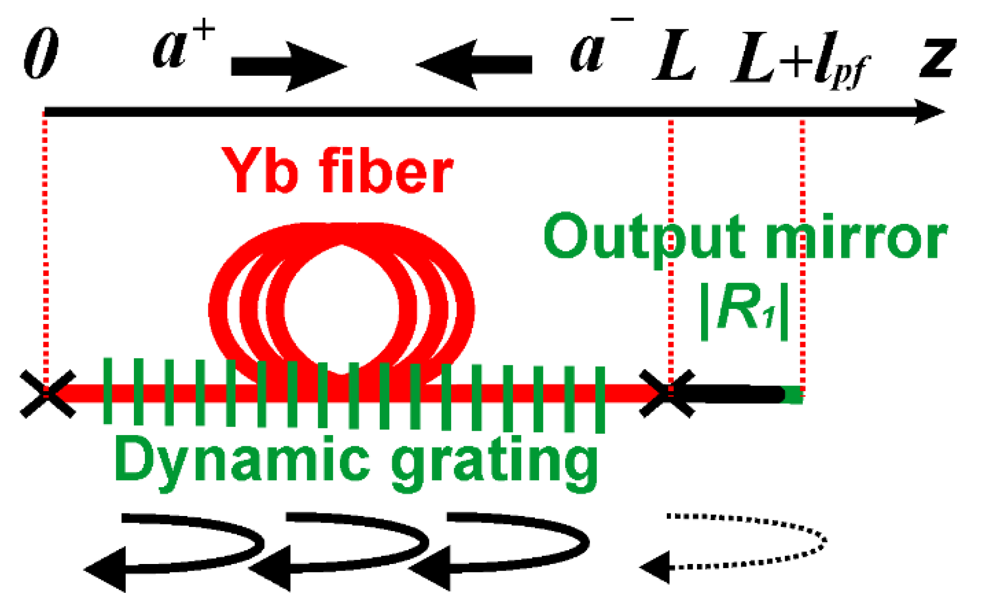
Figure 1. An active FPR formed by a DPG and an output mirror. [Adapted with permission from [40]. © 2017, The Optical Society].
Photonics 09 00613 g001
Figure 2. Reflection spectra for the output mirror (red line), DPG (blue curve), and the active FPR (black) calculated accordingly to expression (1) in the absence of a phase DPG ( Re δ n ˜ = 0 ) for absorbing (a) and gain (b) DPGs (L = 3 m, lpf = 1 m, λ = 1064 nm, e 2 g L 1 = 0.1 , R 1 = 0.04, δ n ˜ = 1.5 × 10 8 ).
Photonics 09 00613 g002
Figure 3. Reflection spectra for the cavity mirror (red line), DPG (blue curve), and the active FPR (black) calculated accordingly to expression (1) in the presence of a phase DPG for absorbing (a) and gain (b) DPG (L = 3 m, lpf = 1 m, λ = 1064 nm, e 2 g L 1 = 0.1 , R 1 = 0.04, δ n ˜ = 1.5 × 10 8 ).
Photonics 09 00613 g003
Figure 4. Experimentally measured reflection spectrum of an active FPR formed in an operating WLSS laser. [Adapted with permission from [41]. © 2019, The Optical Society].
Photonics 09 00613 g004
Figure 5. EDF linear laser with polarization suppression of a standing wave in the gain fiber: (a) experimental setup, (b,c)—lasing spectra without and with a SA, respectively. [Figure 5b,c adapted with permission from [59]. © 1994, The Optical Society].
Photonics 09 00613 g005
Figure 6. Experimental setup of an EDF sigma-cavity laser with the unidirectional suppression of the standing wave in the gain medium with a coupler and isolator. [Adapted with permission from [60]. © 1995, The Optical Society].
Photonics 09 00613 g006
Figure 7. Experimental setup of an EDF sigma-cavity laser with the unidirectional suppression of the standing wave in the gain medium with a circulator.
Photonics 09 00613 g007
Figure 8. Experimental setup of an EDF sigma-cavity laser with a SA based on a PM EDF.
Photonics 09 00613 g008
Figure 9. EDF sigma-cavity laser with a SA with additional pumping: (a) experimental setup and (b) transmission and reflection spectra of the intracavity filters. [Adapted with permission from [68]. © 2006, Elsevier].
Photonics 09 00613 g009
Figure 10. EDF laser with a SA placed in an SM: (a) linear and (b) ring [70] cavity configurations. [Figure 10b adapted with permission from [70]. © 2008, The Optical Society].
Photonics 09 00613 g010
Figure 11. Linear WLSS laser with bidirectional generation: (a) experimental setup, (b) WLSS range at different pump powers. [Adapted from [108] with permission of IOP Publishing. © 2011, Astro Ltd.].
Photonics 09 00613 g011
Figure 12. Linear WLSS laser with unidirectional generation [86]: (ac)—experimental setup, wavelength dynamics for the FBG and SM as high-reflectance mirror, respectively. [Adapted with permission from [86]. © 2011, The Optical Society].
Photonics 09 00613 g012
Figure 13. Experimental setup of a ring WLSS laser with bidirectional generation.
Photonics 09 00613 g013
Figure 14. Sigma cavity WLSS laser: (a) experimental setup, (b) optical spectrum at different time moments, and (c) wavelength dynamics. [Adapted with permission from [104]. © 2020, The Japan Society of Applied Physics].
Photonics 09 00613 g014
Figure 15. Typical intensity dynamics of a WLSS laser (a), dependence of the self-pulsations repetition rate (b) and WLSS rate (c) on the output power and cavity length. [Adapted with permission from [86]. © 2011, The Optical Society].
Photonics 09 00613 g015
Figure 16. Heterodyne signal (a), frequency dynamics for a pulse train (b), and frequency chirp of a single pulse at different pump powers (c). [Adapted from [45] with permission of IOP Publishing. © 2014, Astro Ltd.].
Photonics 09 00613 g016
Figure 17. An example of the mode dynamics for mode-packets when the number of modes N = 2.
Photonics 09 00613 g017
Figure 18. A sigma-cavity WLSS laser: (a) experimental setup, (b,c)—intensity dynamics at different time scales. [Adapted from [42] with permission of IOP Publishing. © 2021, Astro Ltd.].
Photonics 09 00613 g018
Figure 19. A heterodyne signal (a) and its Fourier spectrogram (b) and intensity dynamics for a sequence of mode packets of the Yb-doped CW WLSS laser at different time scales (c,d). [Adapted from [42] with permission of IOP Publishing. © 2021, Astro Ltd.].
Photonics 09 00613 g019
Figure 20. Dependence of absolute (a) and normalized to the laser cavity FSR (b) WLSS rate on the pump power and examples of spectrograms corresponding to different WLSS regimes of the Tm-doped WLSS laser (ce). [Adapted with permission from [113]. © 2019, SPIE].
Photonics 09 00613 g020
Figure 21. WLSS laser with stabilized WLSS boundaries: (a) experimental setup, (be) wavelength dynamics with and without long and short wavelength FBGs. [Adapted with permission from [118]. © 2018, The Optical Society].
Photonics 09 00613 g021
Table 1. Lasers with adaptive filters based on the absorbing fiber.
Ref.SchemeWavelength (nm)/
Linewidth (kHz)
Length and Absorption of SAPower (mW)/
RIN (dB/Hz)
Comments
Erbium
[59]
[50]
Linear
with PC
1532/
<20
0.32 m,
2500 ppm
-/
-
Pioneer work
[60]Sigma1550/
0.95
0.2–6 m,
4.3 dB/m@ 1535
6.2/
−77
Dependence on fiber length
[61]Sigma1522–1562/
0.75
4 m,
-
10/
-
Wavelength tuning
[68]Sigma1550-,
-
-/
-
Additional pump
[67]Sigma1530–1570/
<1.5
0.5–5.5 m
5.27 dB/m @1535
4.7/
−74
PM design of SA
Dependence on fiber length
Dependence on lasing wavelength
[71]Ring1520–1570/
0.7
3.5 m,
-
10/
-
Wavelength tuning
SA in SM
[74]Sigma1565/
-
3 m,
240 ppm
867/
-
Additional filtration
[76]Sigma1550/
0.5
3.6 m,
17.1 dB/m @1530
-/
-
Fast phase control
[78]Sigma1550/
-
6 cm,
148 dB/m @ 1530
-/
-
Very short SA
[75]Sigma1550/
1.09
3 m,
-
12.78/
-
Additional filtration
[63]Sigma1552/
-
2 m,
Fibercore I25, 24.2 dB/m @ 979
Fibercore M12, 12.7 dB/m @ 979
-/
-
Dependence on dopant concentration
Ytterbium
[53]
[54]
Linear
with PC
1064, 1083/
2
1.2 and 5 m
24,000 ppm
18/
-
SA in SM
Dependence on fiber length
Additional filtration
[73]Sigma1053/
10
2 m
-
10/
-
Additional filtration
PM design of SA
[71]Ring1020–1090/1 m,
Nufern SM-YSF-HI
250 dB/m @ 975 nm
2.5/
100
Wavelength tuning
SA in SM
[79]Sigma1069/
0.5
2 m,
Nufern SM-YSF-HI
7/
-
Very narrow linewidth
[77]Sigma1064/
-
2.5 m,
Nufern SM-YSF-HI
-/
-
Dependence on pump wavelength
Thulium
[72]
[80]
Ring2004/6.5 m8.4/
-/
SA in SM
[81]Sigma1957/
20
2 m,
Nufern, PM-TSF-9/125
61.6/
-
PM design of SA
[55]
[56]
Sigma1720/
4.4
0.75 m
Nufern, SM-TSF-9/125
407/
-
Power bistability
[69]Sigma1720/
3.3
1.2 m
Nufern SM-TSF-9/125
2560/
−112
Additional pump
Power bistability
Table 2. Fiber lasers with gain DPG.
Ref.Scheme/
PM-SMF/
Sweeping Range, nm/
Mode Composition
Gain Fiber Comments
Ytterbium
[84]Ring
SMF
@1050/
-
3 m
Liekki-Yb1200-6/125DC
The first observation of WLSS effect in fiber laser
[86]
[87]
Linear (F + SM)
SMF
1062–1078/
Few-mode
2.5 m
Nufern SM-YDF-5/130
The first unidirectional WLSS laser
[108]Linear (F + F)
SMF
1081–1087/
-
11.5 ± 0.5 m
GTwave, 3.1 dB/m.
The first WLSS fiber laser
[85]
[31]
Linear (F + F) & Ring
SMF
1077–1087 (Linear)
1086–1089 (Ring)
Few-mode
5 m
Liekki-Yb1200-6/125DC
Parasitic feedback from connector
[100]Linear (F + F)
SMF
Up to 7 nm @ ~1079/
-
4.85 m
Liekki-Yb1200-6/125DC
WLSS control with power and wavelength of the pump
[92]Linear (F + SM + Filter)
SMF
1087–1094/
SLM
6.5 m
CorActive DC-Yb-8/128
The longest wavelength band for Yb
Two polarization modes
[45]Linear (F + SM)
PM
1058–1078/
SLM & Few-mode
2.6 m
Nufern PM-YDF-5/130
The first mode analysis for WLSS laser
[93]Linear (F + SM/Fiber mirror)
PM
Up to 20 nm @
1028–1080/
SLM & Few-mode
0.3 to 4.3 m
Nufern PM-YDF-5/130
WLSS control with length and temperature of gain fiber
WLSS control with output losses
WLSS control with pump wavelength
[114]Linear (F + F)
SMF
1076–1083
1079–1073/
Few-mode
4.85 m
Liekki Yb1200-6/125DC
WLSS control with pump power
Reverse WLSS
[88]Ring bidirectional
SMF + PC
1039–1036/
Few-mode
1.5 m
CorActive Yb501
Reverse WLSS
[103]Ring bidirectional
PM
1053–1060/
Few-mode
1.5 m
CorActive Yb401-PM
Reverse WLSS
[104]Sigma
SMF
1066–1071/
SLM
1.8 m
CorActive Yb 501
The fist CW WLSS for Yb
WLSS in the scheme with SA
[42]Sigma
PM
100 pm @1064
SLM
1 m
Nufern, PM-YDF-5/130
Forward and reverse WLSS
CW WLSS
[94]Ring bidirectional
PM
Up to 8.3 nm @1050/
Few-mode
1.3 m
Coractive Yb401-PM
WLSS control with incavity losses
Neodium
[99]Linear (F + SM + Filter)
PM
1.8 nm @1064/ SLM3 m
Nufern PM-NDF-5/125
The fist WLSS for Nd
WLSS in doped fiber with 4-level
Bismuth
[46]Linear (F + FLM)
PM
1456–1466/SLM60 m
PM Bi-fiber FORC
Non-RE-doping
The smallest frequency hop ~1 MHz
Erbium
[89]Linear (F + SM + Filter)
SMF
<0.1 nm @ 1550–1565/
Few-mode
3.9 m
EDF
The first Er-doped WLSS laser
Additional filtration (FP filter and Tm-doped fiber)
[101]Linear (F + SM)
PM
2.8 nm @1605/
Two-mode
11 m
IXF-EDF-HD-PM iXblue
The first CW WLSS
The broadest WLSS range for Er
[110]Sigma
PM
40 pm @1560
SLM
2–18 m
Coractive as ER 35–7-PM
CW WLSS
Thulium
[102]Linear (F + SM)
SM
1905–1922/
Few-mode
4 m
Tm-Ho fiber Coractive
The first Tm-doped WLSS laser
[104]Ring bidirectional
SM
14 nm @1970
Few-mode
2.5 m.
TmDF200 OFS
Reverse WLSS
The beating of polarization modes
[95]Linear (F + SM)
PM
26 nm @1920
SLM
5 m
PM-TSF-9/125 Nufern
The broadest WLSS range for Tm
CW to Pulse transition
[96]Linear (F + SM)
PM
1915–1925 (normal)
1920–1910 (reverse)
SLM & Few-mode
5 m
PM-TSF-9/125 Nufern
Normal to forward WLSS transition
Wavelength stopping
[106]Ring bidirectional
SM
1958–1945/
Few-mode
2.5 m.
TmDF200 OFS
Reverse WLSS
The beating of polarization modes
Holmium
[90]
[91]
Linear (F + SM)
SM
4 nm @ 2100
3–5 nm @ 2100/
Few-mode
5–8 m
House-made HDF
The first WLSS for Ho
Length and concentration optimization
[117]Linear (F + SM)
SM
7 nm @ 2070/
Few-mode
0.8, 3, 6 m
House-made HDF
Length and concentration optimization
[97]
[98]
Linear (F+SM)
PM
10 nm @ 2100/
Few-mode
1.05 m
IXF-HDF-PM-8-125 HD IXBlue
The broadest WLSS range for Ho
CW to Pulse transition
Publisher’s Note: MDPI stays neutral with regard to jurisdictional claims in published maps and institutional affiliations.