1. Introduction
In recent years, due to the urgent need to improve the communication capacity, the mode division multiplexing (MDM) system using orbital angular momentum (OAM) modes is considered as a promising scheme to solve capacity trench, which has attracted extensive attention of researchers [
1,
2]. However, the transmission of OAM modes in optical fiber communication system requires special optical fiber structure to match the intensity of the mode. The advantage of OAM mode is that there is a large effective refractive index difference between adjacent modes, and theoretically, there is no crosstalk among different OAM modes. Therefore, the multiplexing of OAM mode does not require complex multiple-input multiple-output (MIMO) technology, which can simplify the composition of the communication system and reduce the cost [
3]. The implementation of OAM multiplexing technology requires research into each module in the system, including laser, optical fiber, amplifier, coupler, mode converter, mode multiplexer/de-multiplexer and so on [
4]. The optical fiber directly determines the transmission distance and performance of the communication link, which is the most critical part of the MDM communication system based on OAM modes.
In order to achieve data traffic enhancement in the MDM system, suitable regions need to be investigated in the radio spectrum of wavelength or frequency. Terahertz wave is the most effective technical means for real-time transmission of large capacity data. Compared with microwave communication, terahertz communication has large bandwidth, high information transmission capacity, high carrier frequency, strong penetration, equipment miniaturization and so on. Compared with laser communication, it has lower requirement for platform stability as well as tracking and aiming system. Additionally, the atmospheric absorption of the terahertz wave is strong, which is conducive to realize space-secure communication. For this reason, the terahertz band is considered as one of the significant regions of the electromagnetic spectrum range. With the development of ultrafast laser technology and continuous expansion of the traditional communication band, the terahertz technology has been increasingly applied in various fields [
5]. The research of terahertz technology has made great progress in radiation source, detecting, sensing and imaging [
6,
7]. However, as an important transmission medium of the terahertz wave, the research of optical devices is still being explored. The reason is that the terahertz wave is between microwave and infrared, and most materials used in microwave and light wave bands, such as glass and plastic, have a strong absorption effect on the terahertz wave, which limits the realization and application of the mature high-frequency microwave and optoelectronic technology as well as the corresponding traditional devices in terahertz band [
8]. At present, the transmission of the terahertz wave is mostly based on free space transmission technology [
9,
10]. Because of the strong absorption of water vapor in the atmosphere, the transmission of the terahertz wave in free space is not only difficult to control the direction, but also has a large absorption loss. Therefore, the optical fiber becomes one of the important means for long-distance terahertz wave transmission. At the same time, the exploration of diversified and new terahertz optical fiber devices has further promoted the rapid development and wide application of terahertz technology.
Up to now, the previous researchers have proposed several waveguides, including metal waveguides and dielectric waveguides. Metal waveguides have low transmission loss and good dispersion characteristics. When the terahertz wave is transmitted on the surface of metal, it will inevitably come into contact with water vapor and dust in the atmosphere, which will degrade the transmission quality of the terahertz wave. To improve the transmission characteristics of the terahertz wave, the fiber as one of dielectric waveguides is proposed to replace the metal waveguide, which exhibits good properties for terahertz wave transmission. The loss caused by the absorption of material in the long-distance transmission should not be ignored. So, the research of terahertz fiber is mainly about porous fiber and hollow fiber. The reason is that hollow-core or porous fiber has no fixed cladding structure; therefore, the arrangement of air holes is relatively random, and the structure is flexible. Additionally, because of the existence of air holes in the cladding, and the most energy of the incident wave will be locally transmitted in the fiber core, which can effectively reduce the absorption loss of material. In addition, the bending loss of the porous fiber is relatively small. As early as in 2002, Han et al. made a solid core PCF by stacking polymer hollow tubes as cladding and solid rods as a core in a hexagonal arrangement [
11]. The transmission loss of the PCF is less than 2.2 dB/cm between 0.1 and 3 THz. Then, K. Nielsen et al. made a novel polymer PCF with Topas material, which can realize low loss and low material dispersion in the terahertz regime of 0.5–0.6 THz [
12]. However, for the terahertz wave, the absorption loss of the polymer material is still high. Lu et al. has designed a hollow-core PCF with regular hexagonal layout cladding. The PCF is based on the anti-resonance reflection transmission mechanism, which can reduce the material absorption loss to 1/30 of the original loss within the frequency range of 0.2–0.8 THz [
13]. Geng et al. simulated and calculated the transmission loss of hollow PCF with hexagonal lattice cladding [
14]. Although the PCF can achieve the transmission loss as low as 0.05 dB/cm, the transmission bandwidth of the fiber is very narrow. The transmission loss of solid core PCF is almost the same as that of polymer fiber, so it is not feasible to realize low loss terahertz transmission by using porous fiber or solid core fiber structure. An effective way to solve the problem of high loss of polymer fiber is to replace solid core or porous fiber with hollow-core fiber. Haisu Li et al. explore terahertz OAM modes supported in multimode Kagome hollow-core fibers. The fiber has a broad bandwidth of 0.25 THz, and the purity values of OAM modes are beyond 0.9 [
15]. As an initial investigation of OAM modes supported in the terahertz fiber, there remains a scope to further scale expand the number of OAM modes with high purity. Therefore, it is urgent to develop a new structure of fiber that can transmit OAM modes over long distances and with low loss.
In this paper, we design a high-performance terahertz PCF for transmission of OAM modes. It combines the merits of hollow fiber and porous fiber, which realizes multiple mode transmission in a wide frequency range. Additionally, it can achieve good mode quality and low confinement loss over a wide bandwidth. The mode purity is over 91%, and the power fraction of the terahertz OAM PCF is higher than 92%. The designed terahertz OAM PCF provides large effective mode area, large numerical aperture and flat dispersion. In addition, the confinement loss is less than the order of 10−7 dB/m over a wide frequency range from 0.2 THz to 0.55 THz. The design of the optical fiber provides a theoretical basis for optical fiber functional devices in the terahertz communication system, and it is of great significance for the practical application of the terahertz wave.
2. Theoretical Model
The electric field components of guided modes for Helmholtz vector equation can be expressed in the form [
16]:
where
n is the refractive index and
K0 is the magnitude of electromagnetic waves in a vacuum. Because the optical fiber is cylindrical structure, the propagation of light wave in the optical fiber is axisymmetric. Therefore, the electric field intensity can be rewritten into the cylindrical coordinate form as:
where
r,
φ and
z are unit vectors in polar coordinate system, respectively.
By expanding the Helmholtz equation in vector form in cylindrical coordinate system, the scalar Helmholtz equation of the longitudinal component of electromagnetic field can be obtained
The equation is solved by the method of separation of variables
The scalar Helmholtz equation can be decomposed into differential equations satisfied by radial functions, which are concretized and expressed as
When solving the above equation, it is necessary to solve the core and cladding separately, then the expression of the longitudinal electromagnetic field component of the mode in the fiber core is
In order to simplify the representation of each component, several parameters are introduced to characterize the mode characteristic structure of the fiber
The radial and angular distribution functions can be obtained by solving the Equation (2)
where
U is the normalized radial phase constant of optical fiber,
J is the Bessel function,
β is propagation constant, and
ω is angular frequency. The constants A and B are determined by the boundary condition of the fiber. According to Maxwell’s equations, the transverse electric field component of the EH mode can be obtained by simplification
Additionally, the electric field expression of HE mode can be obtained by simplification in the same way
The vector expressions of hybrid EH mode can be obtained by converting cylindrical coordinate system into rectangular coordinate system.
Additionally, in the rectangular coordinate system, the expression of the HE mode can be obtained as follows
The OAM modes in optical fiber are composed by the linear combination of the vector eigenmodes. The HE and EH modes are solutions of the vector Helmholtz equation satisfying the fiber transmission conditions [
17,
18,
19]. The OAM mode in optical fiber is specifically expressed in the following configuration:
where
l and
m are integer represent radial and angular order, the superscript “±” corresponds to left-hand and right-hand circular polarization, respectively. Through superposing the even and odd modes with ±
π/2 phase difference, the hybrid modes can be represented by a set of states which carry OAM. Therefore, we can study the characteristics of OAM modes by the even and odd mode of HE or EH.
The electric field expression of the OAM mode can be expressed as
3. Design of the Terahertz OAM PCF
At present, researchers have proposed a variety of optical fibers suitable for OAM mode transmission in MDM communication systems. Among them, PCFs have attracted the attention of many researchers due to their flexible and adjustable structural parameters. This section is mainly about the design strategy of the high-performance terahertz PCF supporting OAM modes. During the process of designing the optical fiber which supports stable transmission for OAM modes, firstly, we should consider that the OAM fiber can hold OAM modes as many as possible and meanwhile avoid higher radial orders modes (m > 1) to be excited to simplify the complexity of OAM mode multiplexing and de-multiplexing modules. Secondly, this kind of the fiber should keep large effective refractive index separation (>10−4) between the HE and EH modes that belong to the same OAM mode group, so as to ensure that the adjacent eigenmodes will not couple into LP modes. Finally, the designed OAM fiber should have good mode quality and propagation properties, including low confinement loss, large effective mode area, low nonlinear coefficient, flat dispersion and high mode purity. Additionally, all the requirements mentioned above should be valid when covering a wide bandwidth.
Low loss and strong anti-interference are important requirements for the design of terahertz OAM fiber, which directly affect the transmission distance of terahertz OAM fiber. Due to the high absorption loss of THz wave in most materials, if common materials are used as the fiber substrate, the hole arrangement in the fiber structure should be used to offset the high absorption loss of the material. By adjusting the duty cycle of the cladding air hole and the doping concentration and thickness of the high-index ring region, the refractive index difference between the fiber core and cladding is increased to improve the anti-interference ability of the fiber.
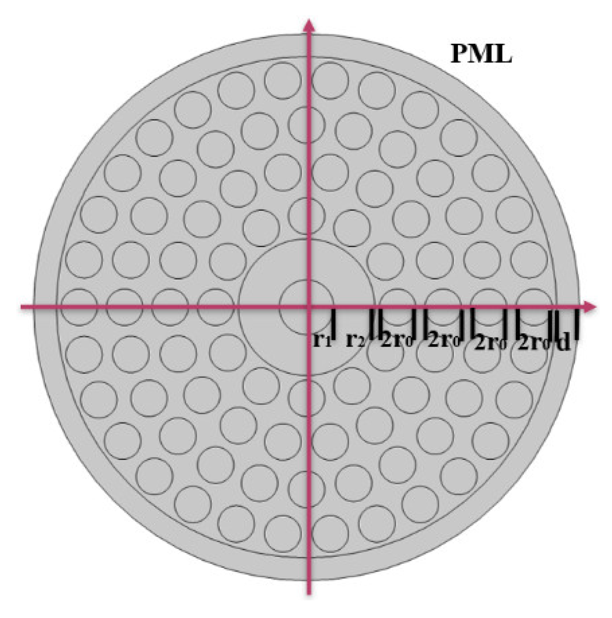
According to the above design strategy, the structure of an improved ring terahertz PCF is presented as shown in
Figure 1. The cladding structure of the fiber is arranged around the inner ring with circular distribution, which enlarges the effective refractive index difference and reduces the degeneracy between the adjacent eigenmodes, thus suppressing the intermodal crosstalk in the transmission process. The radius of the central air hole is
r1, and the cladding consists of four layers of air holes between the inner ring and the outer ring. The radius of circular air holes in the cladding is
r0. The circular arrangement of the cladding makes the middle annular mode transmission area match with the circular distribution of the OAM mode field very well, which can effectively prevent the energy of high-order modes from leaking into the cladding. The thickness of the central ring region conducting light is
r2, which is made of TOPAS material with refractive index of 1.53. The base material is made of Polytetrafluoroethylene (PTEE) with the refractive index of 1.43. Periodic air holes with the refractive index of 1 are arranged on the circular concentric as a cladding.
Compared with ordinary ring terahertz OAM fiber, the terahertz OAM PCF has more adjustable structural parameters, which plays a positive role in obtaining better transmission characteristics. However, this also increases the difficulty of optimizing the fiber structure, because many of the best parameters are chosen in opposition to each other and cannot be optimized at the same time. The characteristic parameters r0, r1, and r2, are the air hole radius, the inner air hole radius, and the thickness of circular shape region, respectively. Since the thickness of the high refractive index ring region in the fiber core determines the quality of the mode, we can reduce the spin–orbit coupling effect and increase the anti-disturbance performance by adjusting the thickness of ring region. The average refractive index of cladding area is the mean value of three regions weighted with the areas they occupy, and the air filling fraction affects the index contrast between ring core and cladding area. In order to obtain the optimal parameters of the terahertz OAM PCF, we optimized the parameters of cladding air hole radius and the inner core radius. We measure the mode stability of the designed terahertz OAM PCF by the effective refractive index separation between the adjacent HE and EH modes that belong to the same OAM mode group.
In the simulation, a perfect matching layer (PML) with the thickness of
d is added outside the cladding. The OAM modes transmitted in the fiber will be pulled to the ring high refractive index region formed between the inner air hole and the outer first layer air holes. We first fix the size of the high refractive index ring region and then calculate the influence of the air hole radius (
r0) in the cladding on the quality of the mode. When inner air hole radius (
r1) is 140 μm,
Figure 2 shows the effective refractive index and the effective refractive index difference as a function of the air hole radius (
r0) for different vector modes, respectively. The modes represented by the different-colored solid lines with the same marker in the figure can be synthesized into the same OAM mode group. As can be seen from
Figure 2a, the effective refractive index decreases with the increase in air hole radius (
r0). In
Figure 2b, the effective refractive index difference between adjacent modes increases with the increase in air hole radius (
r0), and the large effective refractive index differences can maintain the stable transmission of OAM modes. The change in the effective refractive index difference for air hole radius (
r0) on higher-order mode is larger than that of lower-order mode. This is because the higher the air hole filling fraction, the lower the average refractive index of cladding, and the greater the refractive index contrast of the corresponding core and cladding. We should choose as large an air hole as possible to increase refractive index contrast, but the PCF structure will become unstable as the air hole radius increases. In addition, the more air hole layers in the cladding, the stronger the constraint ability to the light would be. In practice, the four-layer air hole array is enough to ensure the stable transmission of OAM mode in the optical fiber. Therefore, considering the trade-off between the fabrication difficulties and excellent properties, we choose the air hole radius of 90 μm.
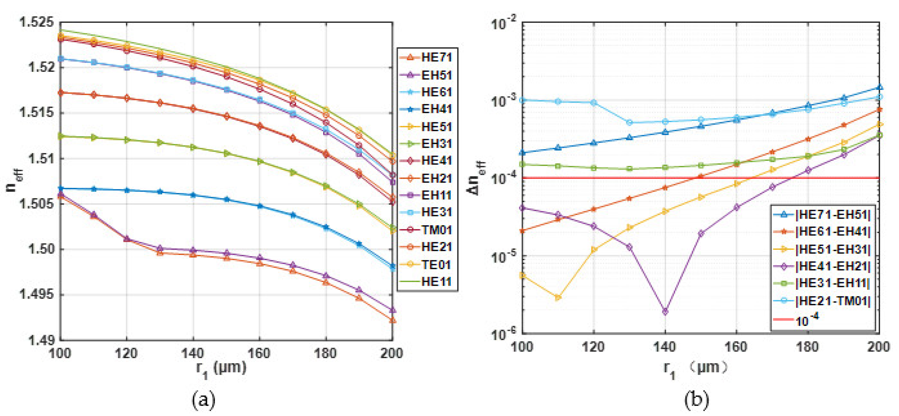
As the thickness of the high refractive index ring region changes, the effective refractive index of each mode transmitted in the fiber will also change.
Figure 3 illustrates the effective refractive index and the effective refractive index difference as a function of the inner radius (
r1) for different vector modes. It can be seen from
Figure 3a that the effective refractive index of the vector mode decreases with the increase in the vector module order. The effective refractive index of each vector mode is within the range of 1.56–1.62. In addition,
Figure 3b shows that the effective refractive index difference in some EH modes and HE modules is relatively close. In order to ensure the HE and EH modes of the same mode group in the optical fiber have a large effective refractive index separation, we should choose the inner air hole radius (
r1) larger than 160 μm. In general, the generation of higher-order radial modes in the optical fiber will greatly increase the complexity of mode de-multiplexing. For purpose of avoiding the appearance of the higher radial orders OAM modes, we should choose the size of the high refractive index ring region as thin as possible in the fiber design. However, the OAM fiber with a thin ring structure can cause mode quality degradation and larger confinement loss. In order to balance the appearance of higher-radial-order mode and good mode quality, a compromise method is adopted. Considering all the above factors, we fixed inner air hole radius (
r1) at 170 μm. Main parameters of the designed terahertz OAM PCF are provided in
Table 1.
4. Properties of the Designed Terahertz OAM PCF
In this section, the COMSOL Multiphysics software is applied to investigate the transmission characteristics of the designed terahertz OAM PCF. As shown in
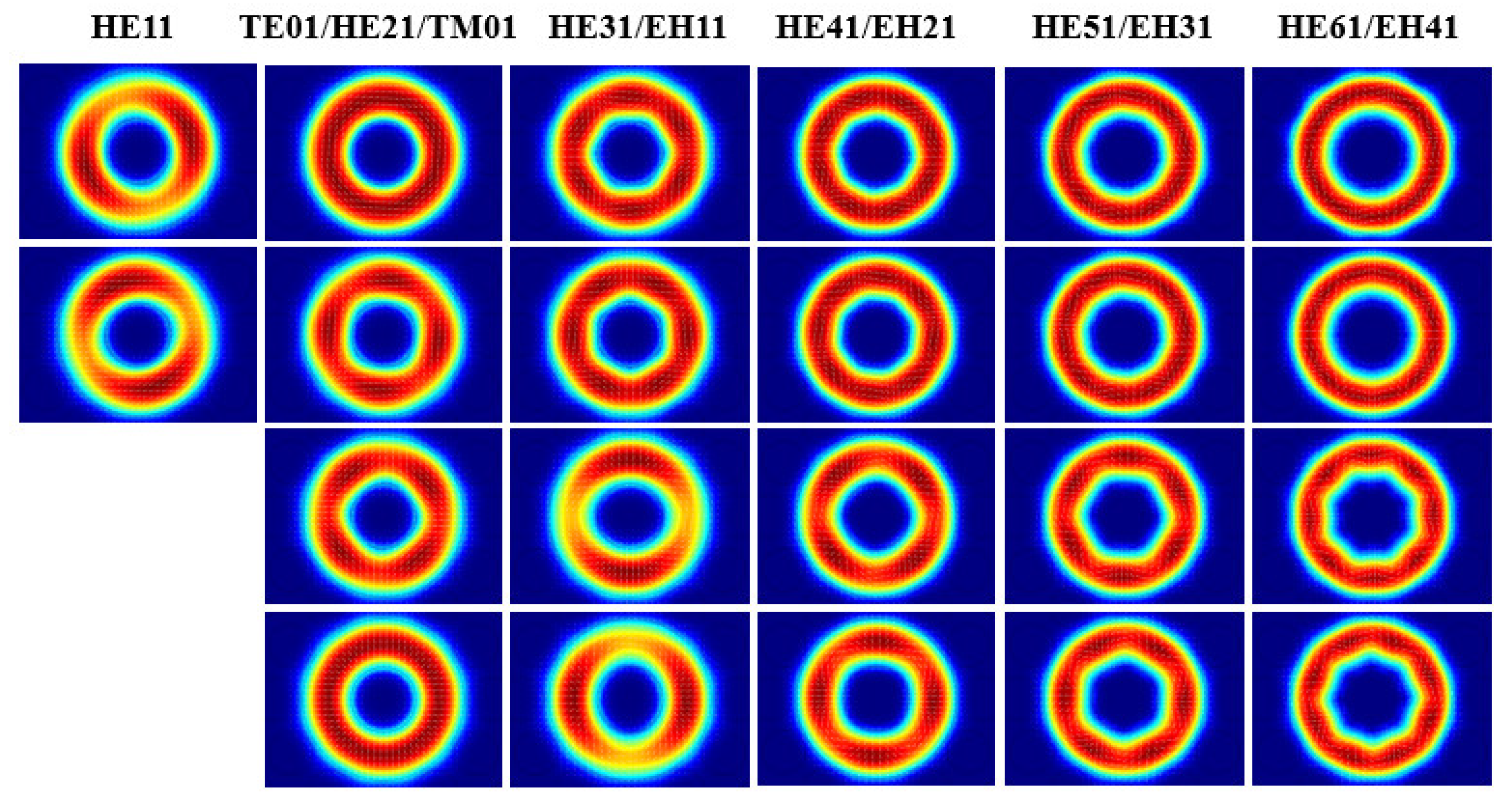
Figure 4, we simulated the electric field intensity distribution of eigenmodes supported in the designed terahertz OAM PCF at the frequency 0.4 THz. All the vector eigenmodes can be well transmitted in the fiber. Each column of the mode diagrams in
Figure 4 represents the mode basis composition that synthesizes the same order of OAM mode. The fiber can hold OAM modes as many as possible and meanwhile avoid higher radial modes to be excited to simplify the multiplexing and the demultiplexing of OAM modes. This designed fiber has no high-order radial mode, which makes it widely applicable to MDM communications systems.
According to the calculation of Equation (8), the OAM mode can be expressed as the superposition of odd and even mode of the same vector eigenmode with the phase difference of π/2. From
Figure 5, the electric field intensity distribution of the OAM mode presents a circular distribution, and it can be well confined to the core area. The first row of
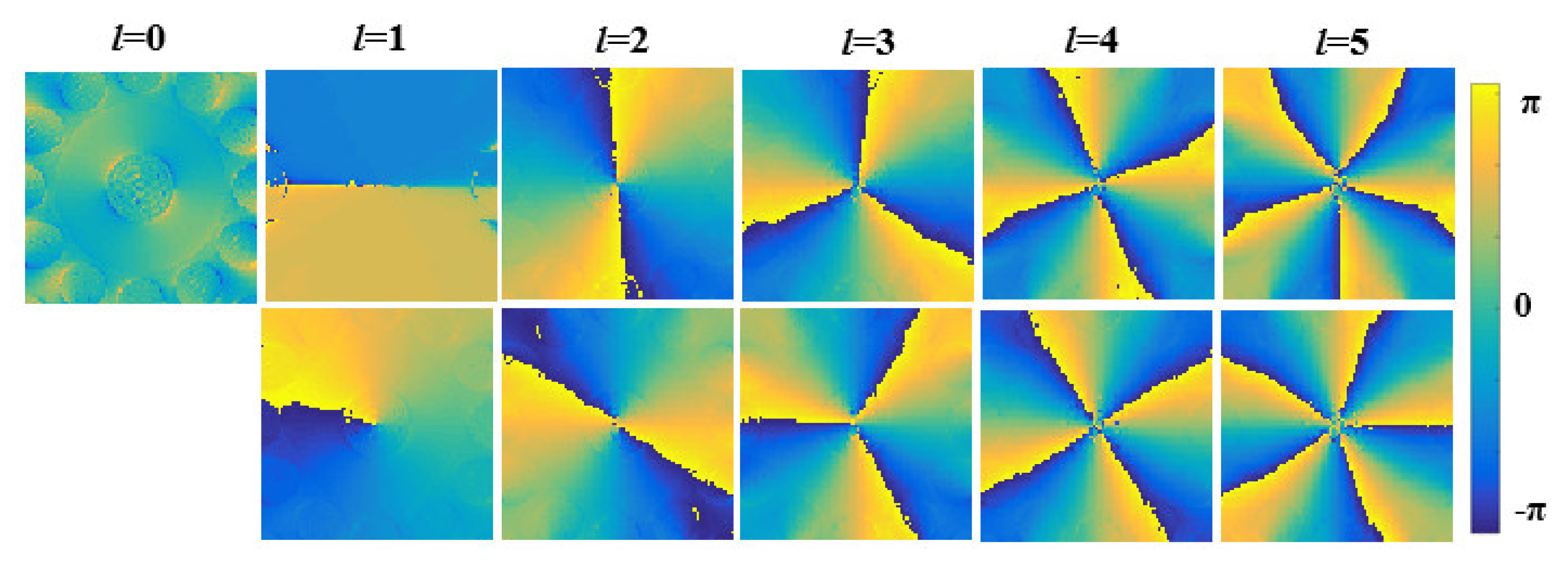
Figure 5 is the OAM mode composed of the odd and even modes of HE mode, while the second row is the same order OAM mode composed of the odd and even modes of EH mode. In addition, we also give the phase distribution of the OAM mode in the terahertz OAM PCF in
Figure 6. Each column of the phase diagrams represents the mode basis composition that synthesizes the same order of OAM. The number of phase transversals represents the topological charge of the OAM mode. The major purpose of this designed fiber is to achieve the high purity OAM light and decrease the channel crosstalk for the OAM optical fiber communication system. Therefore, we first qualitatively analyze the purity of the OAM light through its intensity distribution and polarization characteristics [
20].
Figure 7 shows the polarization distribution of the OAM mode in the terahertz OAM PCF. The ellipticity of each small colored circle is defined as the ratio of the x component to the y component of the OAM mode electric field, and the ellipse shape represents the polarization characteristics of the OAM light, and the ellipse area means the energy amount in that region. A high refractive index contrast and thin ring design will cause strong spin–orbit coupling effect. When spin–orbit coupling occurs, the OAM and spin angular momentum (SAM) of the mode cannot exist independently. At this time, the mode in the OAM fiber is no longer pure OAM mode, and which becomes the mixture state of different OAM modes. An additional OAM mode with opposite polarization state and the topological charge difference of 2 is generated in the designed OAM fiber. Therefore, the polarization state of the impure OAM mode is no longer an ideal circular polarization state, and which becomes an elliptic polarization state varying with the spatial position. The smaller the ellipticity value in the figure is, the more serious the spin–orbit coupling effect of the OAM mode is. The modes in
Figure 7 are arranged according to the azimuth of circular polarization, and the direction.
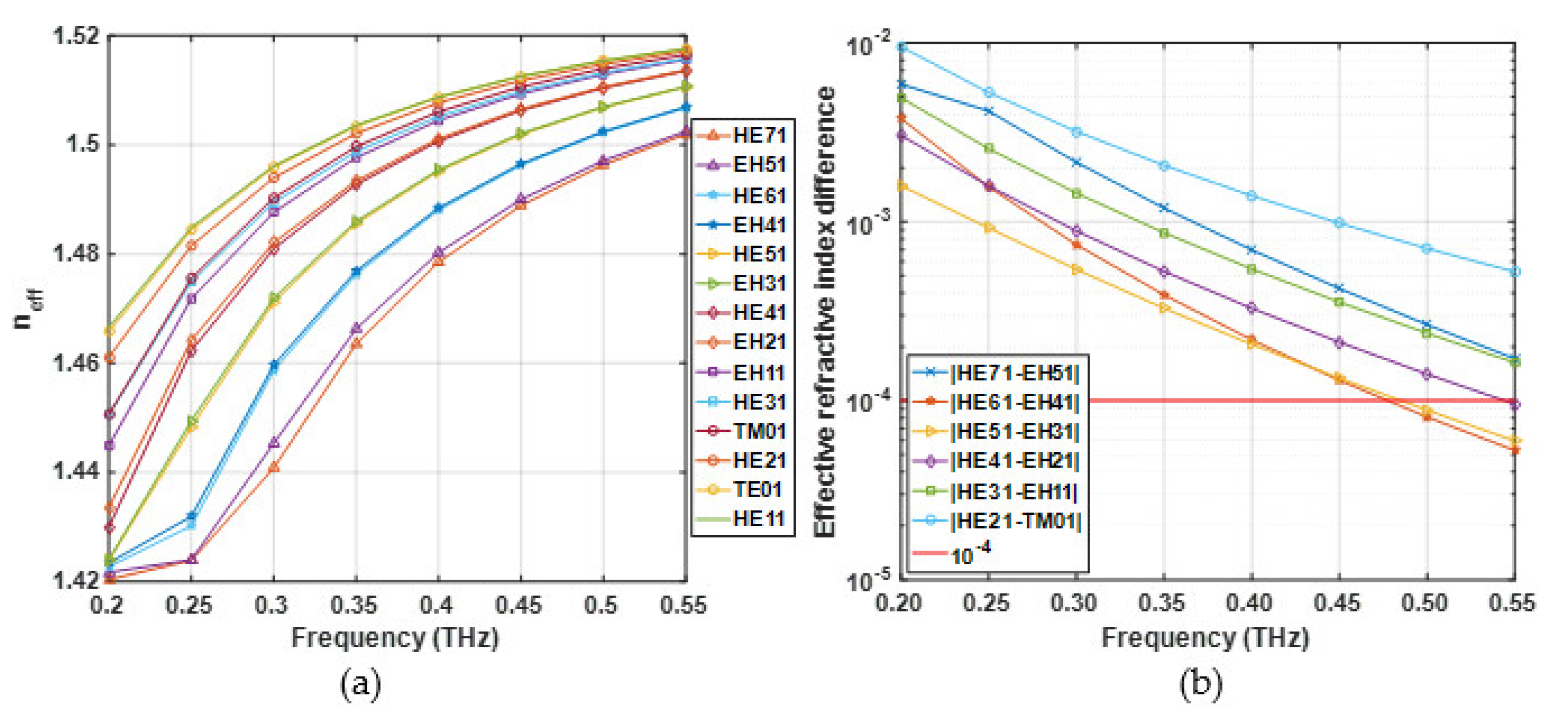
The effective refractive index of the different vector modes is lies between 1.48 and 1.62, as shown in
Figure 8a, which increases with the increase in the frequency. The EH and HE modes of the same mode group have similar effective refractive index. Then, the effective refractive index difference between adjacent modes supported by the designed PCF is given in
Figure 8b. It can be seen that the effective refractive index for EH and HE modes decrease with the increase in the frequency. The effective refractive index difference for EH and HE modes are above 10
−4 with the frequency range between 0.2 THz and 0.45 THz, which ensures that the OAM modes can be well separated and avoid degeneracy into LP modes. Due to the large effective index separation between the corresponding HE and EH modes for the same OAM mode group, the designed terahertz OAM PCF can realize stable transmission of OAM mode over long distances and broadband.
The dispersion of the optical fiber could cause the transmission signal to broaden, which degrades the communication quality. Excessive dispersion would result in the decrease in communication capacity and the limitation of communication distance. In the process of optical fiber design, the dispersion characteristic should be flat to reduce its influence on the mode transmission quality in the optical fiber. According to the references [
21,
22], the value of dispersion can be calculated as:
The relation between dispersion and frequency for different vector modes is shown in
Figure 9. The dispersion of higher-order mode decreases obviously with the increasing frequency. However, the dispersion of lower-order mode decreases slowly with the increasing frequency, the trend is relatively gentle. In particular, the high-order modes show a higher dispersion profile, the dispersion is lower than 2.22 ps/THz/cm of the HE
71 mode at the frequency of 0.2 THz. It can be seen that compared with the existing OAM PCFs, dispersion of the proposed terahertz OAM PCF is lower and flatter. Moreover, the lower dispersion profile with lower dispersion variation within the operating terahertz frequency spectrum is good for the efficient transmission of the OAM modes.
Confinement loss is an important optical parameter to evaluate the performance of optical fiber, which is the result of the energy leakage into the cladding region. Confinement loss affects the transmission distance of optical fiber. It is mainly determined by the imaginary part of the effective refractive index and can be calculated through the following equation [
23,
24]:
Table 2 shows the highest confinement loss of the different modes for the proposed terahertz OAM PCF with frequency ranging from 0.20 THz to 0.55 THz. The highest confinement loss is about the order of 10
−11 dB/m except for mode EH
51 and HE
71. The low confinement loss is beneficial to steady transmission of the OAM modes, and the light beam can propagate well in a high indexed material doped circular ring. The four layers of air holes in the cladding prevent the energy leakage in the annular region. Therefore, the terahertz OAM PCF would be a strong candidate for long-distance and high-capacity optical fiber communication.
The nonlinear effect in optical fiber is also a crucial parameter, which has a significant impact on the mode transmission quality. The large effective mode area and low nonlinear coefficient are conducive to the suppression of the nonlinear signal distortion in optical fiber. Therefore, in the fiber design and fabrication, it is necessary to ensure that the optical fiber has a large effective mode area to improve the mode transmission quality. The effective mode area is expressed by [
24]:
Here,
E(x, y) is the electric field distribution on the cross section of the optical fiber. The effective mode area as a function of frequency for different modes supported by the proposed terahertz OAM PCF is plotted in
Figure 10. The effective mode area decreases with the increase in frequency. That is because the energy of the mode is more likely to leak into the cladding, and it is more difficult to confine the light into the high refractive index ring region at larger frequency. One can find that the mode area of the vector modes is above 1.04 × 10
−7 m
2, and the maximum mode area can reach 1.96 × 10
−7 m
2.
The numerical aperture is also known as the optical acquisition area, and the ability of the receiving end to collect light beam completely depends on the size of numerical aperture. The high numerical aperture can be obtained by increasing the effective mode area of the optical fiber. The numerical aperture of the optical fiber can be given as [
25,
26]:
Figure 11 shows the numerical aperture for different modes as a function of frequency ranging from 0.20 THz to 0.55 THz. As can be seen from
Figure 11, the numerical aperture curves of all models are very close, and the numerical apertures of different modes decrease with the increasing frequency. The proposed terahertz OAM PCF shows a maximum numerical aperture 0.92 at 0.20 THz frequency for the mode of HE
71. The terahertz OAM PCF has a large numerical aperture, which makes it play an important role in OAM long distance transmission optical fiber communication system.
The power fraction is an important optical parameter to examine a terahertz optical device. It determines the amount of terahertz light passing through the fiber core area, which indicates the percentage of the fiber core to the total power. According to the Poynting theorem, the power fraction of the proposed terahertz OAM PCF can be evaluated as [
26,
27]:
where
Ex and
Hx are x component of electric field intensity and magnetic field intensity, respectively.
Ey and
Hy are y component of electric field intensity and magnetic field intensity, respectively.
Figure 12 illustrates the power fraction as a function of the frequency ranging from 0.20 THz to 0.55 THz. As can be seen that with the frequency increases, the power fraction of each mode also increases, and the higher-order mode shows a slightly lower power fraction than the lower-order mode at any frequency. When the frequency exceeds 0.45 THz, the proposed terahertz OAM PCF reaches the maximum power fraction 99%.
Mode purity represents the quality of OAM mode, which is evaluated by the light intensity overlap between the target mode and the total mode of PCF as below [
28,
29]:
Here,
E is the electric field vector. The change in the mode purity of all vector modes supported by the proposed terahertz OAM PCF with frequency ranging from 0.20 THz to 0.55 THz is shown in
Figure 13. As can be seen, the mode purity of all modes increases as the frequency increases, ranging from 91% to 96%. In addition, the mode purity of the lower-order mode is higher than that of the higher-order mode. In the optical fiber communication system, high mode purity ensures better mode multiplexing and de-multiplexing as well as stable transmission of optical signals.


