Article

Phase-Shift Laser Ranging Technology Based on Multi-Frequency Carrier Phase Modulation

1
Aerospace Information Research Institute, Chinese Academy of Sciences, Beijing 100094, China
2
University of Chinese Academy of Sciences, Beijing 100049, China
3
Key Laboratory of Space Laser Communication and Detection Technology, Shanghai Institute of Optics and Fine Mechanics, Chinese Academy of Sciences, Shanghai 201800, China
*
Authors to whom correspondence should be addressed.
Photonics 2022, 9(9), 603; https://doi.org/10.3390/photonics9090603
Submission received: 26 July 2022 / Revised: 17 August 2022 / Accepted: 22 August 2022 / Published: 25 August 2022
(This article belongs to the Section Lasers, Light Sources and Sensors)

Abstract

:
Compared to traditional phase laser ranging technology, phase-shift laser ranging technology based on carrier phase modulation has significant advantages, such as simple modulation and demodulation, as well as simultaneous ranging and velocity measurements with high precision. To expand the range and ensure the ranging precision in carrier phase modulation in phase-shift laser ranging technology, we propose a phase-shift laser ranging system based on multi-frequency carrier phase modulation. We analyzed the effects of the stagger coefficient, modulation depth, and signal-to-noise ratio on the ranging precision by simulation. Finally, we built an experimental system with a range of 300 m by choosing appropriate parameters and conducting linearity and range precision tests. The experimental results show that the system has good linearity, and the ranging precision can reach 1 cm when the signal-to-noise ratio is 20 dB.

1. Introduction

Phase-shift laser ranging technology can achieve millimeter precision at medium and long distances and is widely used in aerospace and civil fields for spacecraft rendezvous and docking, terrain mapping, and robot navigation [1,2,3]. The traditional phase rangefinder often increases the modulation frequency to improve its precision. However, the optical signals in semiconductor lasers become distorted when these lasers are modulated at high frequencies [1,4]. In addition, as the traditional phase rangefinder uses direct detection, it is easily affected by ambient light. To resolve the aforementioned problems, a phase-shift laser ranging technology based on carrier phase modulation has been proposed and verified in previous studies, demonstrating the advantages of high ranging precision and solid anti-jamming ability [5,6]. To expand the range and ensure ranging precision, traditional phase laser ranging technologies generally use multiple frequencies for ranging [7,8,9]. Furthermore, interferometry uses multi-wavelengths to eliminate range ambiguity [10,11]. In a multi-frequency phase ranging system, there are mainly two types of ranging technologies with varying frequency differences: coarse-fine ranging with a large frequency difference and stagger multi-frequency ranging with a small frequency difference [12]. In the coarse-fine ranging system, there is a significant frequency difference between a coarse ruler and the corresponding fine ruler, which requires the system to maintain the same response over a wide spectrum range [13,14]; however, the staggered multi-frequency ranging system is not subject to this restriction. Therefore, a multi-frequency ranging system mainly adopts the stagger multi-frequency mode [15] and avoids large frequency differences. If multiple frequencies are transmitted through time-sharing, the position of the target will change during the measurement process, and the results from multiple gauges cannot be aligned; therefore, the accurate distance of the target from the rangefinder cannot be measured [16]. Therefore, when there is relative motion between the radar and the target during the measurement process, it is necessary to simultaneously transmit and receive all the rulers. A previous research study [5] utilized a de-phase algorithm via phase unwrapping to reconstruct the original phase of a signal; however, the running velocity was relatively slow. The laser frequency also changes according to the sine law as the sinusoidal signal modulates the phase of the laser. Therefore, frequency discrimination demodulation can be used to perform high-speed demodulation of a signal.
In this study, we investigated a phase-shift laser ranging technology based on multi-frequency carrier phase modulation. For the first time, signals with multiple frequencies were modulated onto the phase of a laser, and were extracted by a differential demodulation to measure the phase difference of each frequency component and resolve the distance ambiguity.

2. Methods

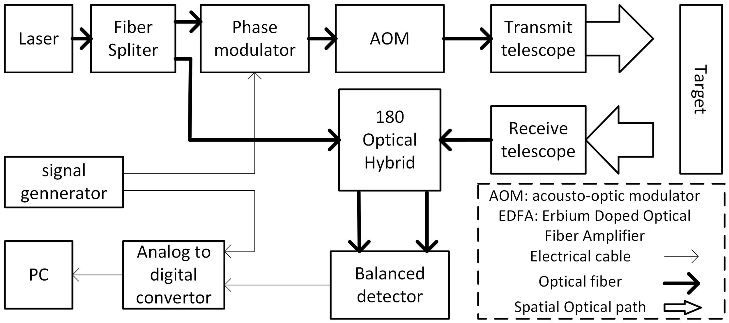
The schematic diagram of a phase-shift laser ranging system based on multi-frequency carrier phase modulation is shown in Figure 1. The beam emitted by the laser is split into two channels by a beam splitter, one of which is modulated by an electro-optic phase modulator (PM) and an acousto-optic modulator (AOM) driven by the signal generator. The beam is then transmitted through the atmosphere using a transmitting telescope. Following transmission, the laser beam is scattered by the target surface. The received backscattered light and local vibration light are mixed using a 180° optical bridge and then detected by a balanced detector. An analog-to-digital converter (ADC) samples the sinusoidal signal generated by the signal generator and the signal output by the balanced detector. The ADC then outputs the sampled digital signal to the signal processing unit to calculate the velocity and distance of the target. Considering that the local oscillator light power is significantly strong and the power jitter can be ignored, the main source of noise in the system is shot noise, which is caused by the local oscillator light power [17,18]. The sampled output signal of the balanced detector can be expressed as follows:
i B D ( n ) = α { | E s E l o | cos [ φ I F ( n ) ] + i N ( n ) }
Here, α is the gain of the balanced detector, is the responsiveness of the detector, n indicates the number of samples, n = 1 , 2 , 3 , , N . i N ( n ) indicates the sampled shot noise, and E s and E l o are the optical fields of the signal and oscillator lights, respectively.
φ I F ( n ) indicates the phase of the output signal, which can be expressed as follows:
φ I F ( n ) = 2 π ( f d + f A ) n F s + i = 1 M κ i cos [ 2 π f i ( n F s l R F + 2 r 0 c ) + φ R F i ] + φ o
where F s is the sampling rate, c is the velocity of light in the vacuum, and φ o is the phase difference between the local oscillator and signal lights. f A is the frequency shift produced by AOM, and κ i , f i , and φ R F i are the phase modulation depth, modulation frequency, and initial phase of the i th scale, respectively. l R F is the distance of the radio frequency signal transmitted within the ranging system and r 0 is the distance from the target to the receiving and transmitting faces of the rangefinder. f d = 2 ν 0 / λ is the Doppler shift caused by the target motion, where ν 0 is the velocity of the target and λ is the wavelength of the light wave. The collected data were processed to calculate the velocity and distance of the target. The basic principles for calculating the velocity and distance are described in the following. First, by performing spectrum analysis of i B D ( t ) , the peak of the spectrum can be obtained as f p e a k = f d + f A . Thus, the measured velocity of the target can be expressed as follows:
v m = λ 2 ( f p e a k f A )
The frequency shift of the signal is then performed such that the central frequency of the signal becomes f A . Next, the signal is processed by a discriminator that extracts the modulating signal. A discriminator is composed of differentiators, an envelope detector, and a low-pass filter. The envelope detector extracts the modulating signal, or envelope signal, from an amplitude-modulated signal [19]. A low-pass filter passes low-frequency signals and blocks or impedes high-frequency signals. Finally, the DC offset is removed from the signal. After being processed by envelope detection, low-pass filtering, and removal of the DC offset, the demodulated signal is expressed as follows:
s d m ( n ) = α | E s 2 E l o | i = 1 M 2 π f i κ i sin [ 2 π f i ( n F s l R F + 2 r c ) + φ R F 0 i ]
The frequency spectrum of the demodulated signal is analyzed, and the phase φ s 1 , φ s 2 , ⋯, φ s M of each frequency component f 1 , f 2 , , f M is obtained. In addition, the frequency spectrum of the collected multi-frequency drive signal is analyzed, and the phase φ s 1 , φ s 2 , ⋯, φ s M of each frequency component f 1 , f 2 , , f M is obtained. The ruler frequency selection and de-ambiguity principle are as follows:
(1) The fundamental frequency f 0 is selected. The corresponding maximum unambiguous range is R 0 .
(2) Provided that M ruler frequencies are transmitted, the frequency value is f i = f 0 j = 1 M m j / m i ( i = 1 , 2 , , M ) , and the maximum unambiguous range R i = m i R 0 / j = 1 M m j corresponds to the i th ruler. m i is a co-prime positive integer that can be called the stagger coefficient.
(3) Therefore, the maximum unambiguous range can be extended to R 0 .
The error function is defined as follows:
F = i = 1 M 1 j > i M ( L i L j ) 2
where
L i = k i m i + Δ φ i + δ ( Δ φ i ) 2 π m i
Here, Δ φ i is the phase difference of the i th ruler, and δ ( Δ φ i ) is the phase error due to noise. Obtaining ( k i , k 2 , , k m ) minimizes F, and the estimated distance of the target can be obtained as r m = 1 M i = 1 M L i .

3. Results

3.1. Simulation Analysis

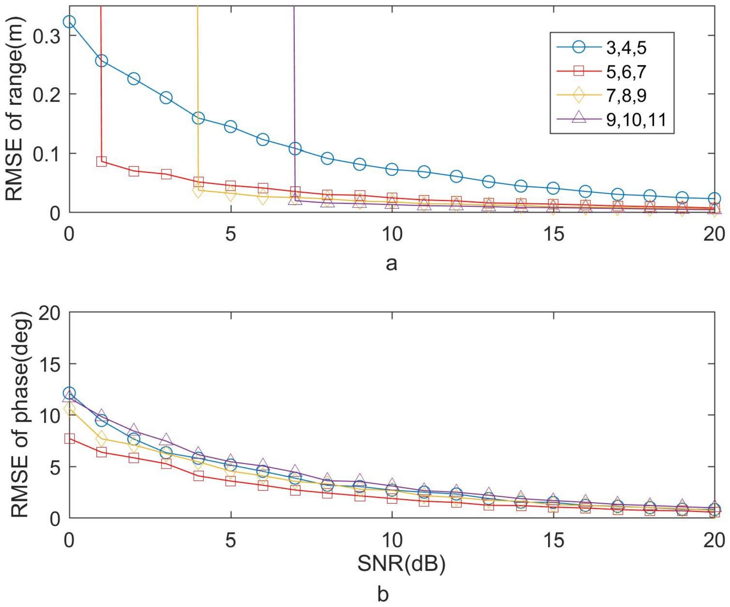
A simulation analysis of the system was performed; the frequency of the sampling rate and frequency shift were set to 500 and 80 MHz, respectively. The fundamental frequency was 500 kHz, the corresponding range was 300 m, and three ruler frequencies were used to measure the distance of the target. The following four groups of stagger coefficients were chosen: (3, 4, 5), (5, 6, 7), (7, 8, 9), and (9, 10, 11). We intercepted 16,383 sampling points to calculate the distance. A white Gaussian noise that simulates the shot noise was added to the signal. This study used the root mean square error (RMSE) to represent the ranging precision. Variations in the ranging and phase measuring RMSE with the signal-to-noise ratio (SNR) under different stagger coefficients are provided in Figure 2, where the modulation depth ( κ ) is π / 3 . As shown in Figure 2, the RMSE of the range increases sharply when the SNR decreases to a certain value for each stagger coefficient. This phenomenon occurs due to the algorithm failure caused by the phase error due to a low SNR. A smaller stagger coefficient leads to a higher phase error tolerance when the distance ambiguity is solved. However, if a smaller stagger coefficient is chosen, lower ruler frequencies will result in poor ranging precision. When the stagger coefficient is small, increasing the stagger coefficient can reduce the phase error; the greater the stagger coefficient, the greater the frequency of the measuring ruler. When the ruler frequency reaches a certain point, the bandwidth of the signal will exceed the bandwidth of the system, resulting in the distortion of the collected signal, which will increase the phase measurement error.
The influence of the modulation depth on the ranging precision was simulated and analyzed. The variation in the ranging RMSE (with the modulation depth for different SNRs) is shown in Figure 3, which demonstrates that under the condition of a certain SNR, with an increase in κ , the ranging RMSE increases and is followed by a decrease. When the system bandwidth is sufficiently wide, an increase in the modulation depth would cause more energy of the signal to leak to the sideband, thus reducing the ranging precision. When the modulation depth increases to a certain extent, the signal bandwidth exceeds the system bandwidth; therefore, the ranging RMSE begins to increase.
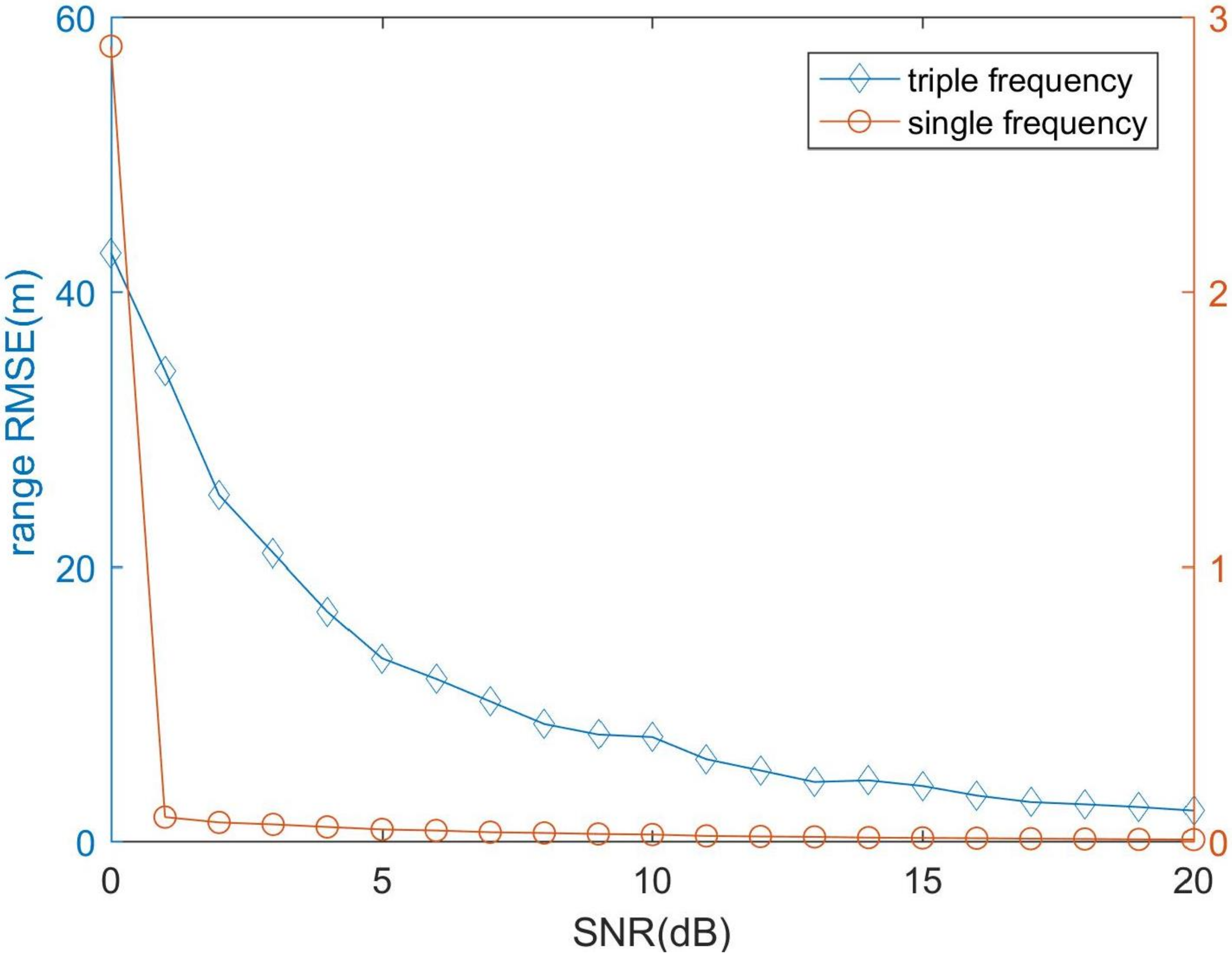
Simulations of range measurement precision with triple frequencies and a single frequency modulation were conducted to demonstrate the performance improvement with multi-frequency modulation. A ruler frequency of 500 kHz was chosen for the single frequency modulation, which resulted in a measurement range of 300 m. A basic frequency of 500 kHz and stagger coefficient of (5, 6, 7) were chosen for the triple modulation. For the multi-frequency modulation, the corresponding frequencies were 21, 17.5, and 15 MHz. The maximum measurement range of the rulers was 10 m. The measurement was expanded 30 times when using multi-frequency modulation. The variation in the ranging RMSE (at various SNRs for single and triple frequencies) is shown in Figure 4. When the SNR was 20 dB, the RMSE of the single and triple frequency modulations were 0.067 and 2.248 m, respectively. The results demonstrate that multi-frequency ranging ensures the precision of the range measurement while improving the measurement range.

3.2. Experimental Devices

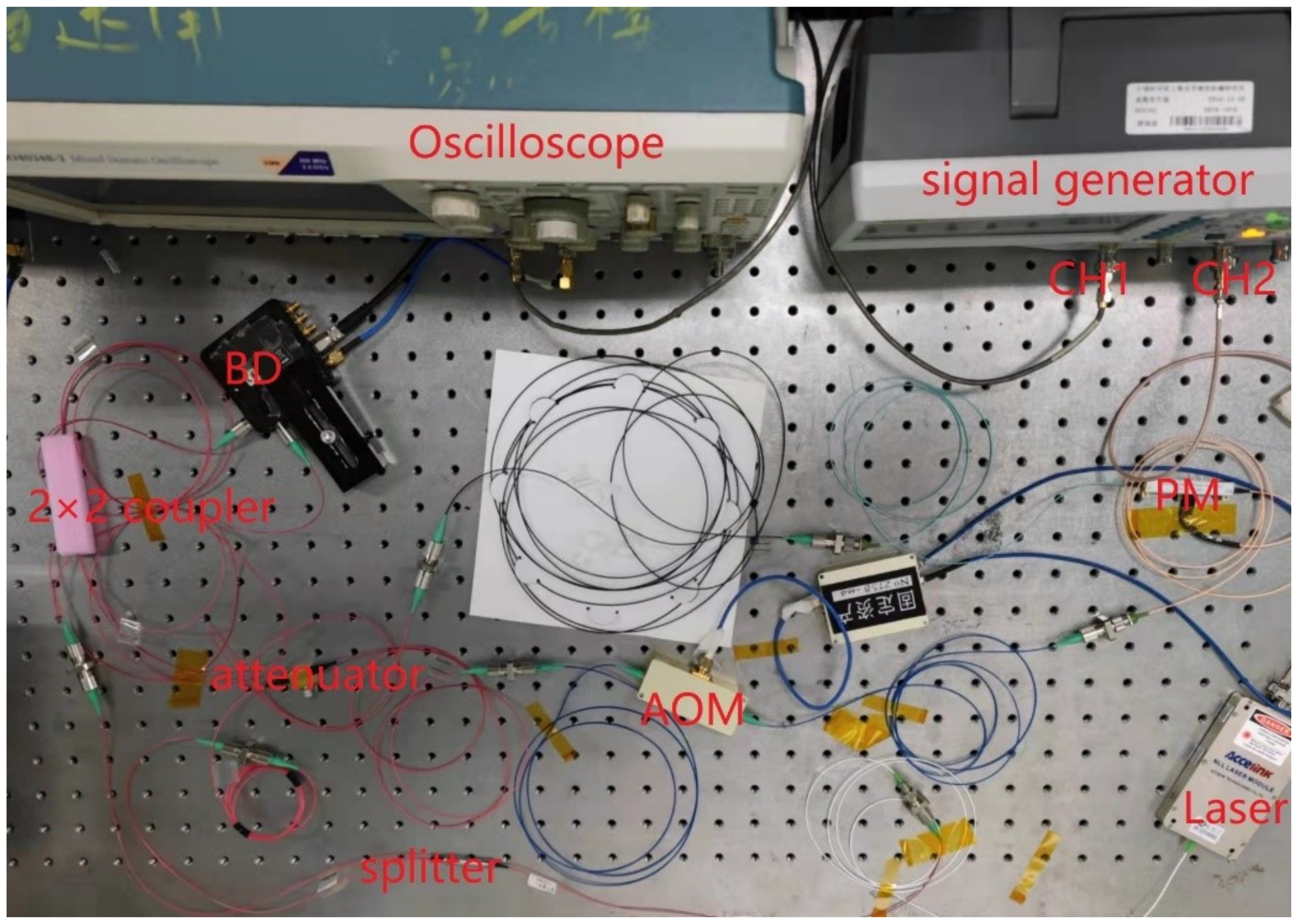
The experimental system setup is presented in Figure 1. The transmitter and receiver were connected to an optical fiber. A photograph of the experimental setup is provided in Figure 5. The selected fundamental frequency was 500 kHz, the maximum unambiguous range was 300 m, and the stagger coefficient was (5, 6, 7). The output signal of the signal generator contained the following three scale frequencies: 21, 17.5, and 15 MHz. The amplitude of each frequency component was 1.333 V and the half-wave voltage of the PM was 4 V; therefore, the modulation depth was π / 3 . A semiconductor laser with a theoretical line width of 10 kHz was used in the experiment. AOM SGTF80-1550-1P from Smart Science & Technology, PM KG-PM-15 from Conquer Photonics, and balance detector 1617-AC from NEW FOCUS were used. An oscilloscope was used to collect the signal with the sampling rate set to 500 MHz; 16,383 sampling points were intercepted each time to calculate the velocity and distance of the target.

3.3. Results and Discussions

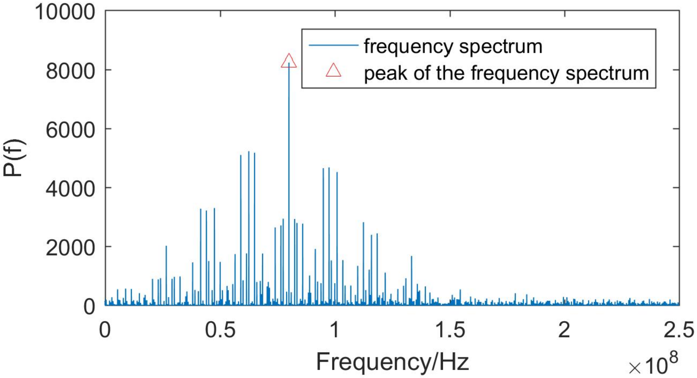
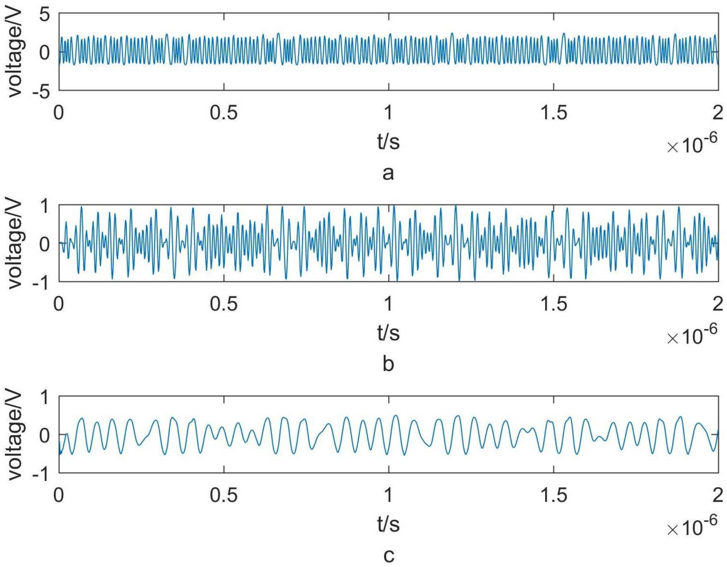
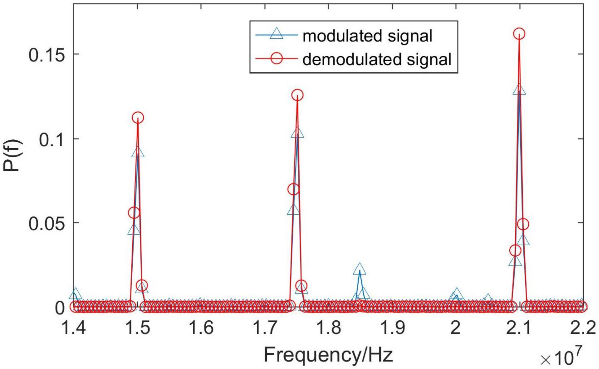
The spectra of the signals and their peak are presented in Figure 6. The signal processing is demonstrated in Figure 7. First, the signal spectrum was obtained using fast Fourier transform (FFT). The peak of the spectrum corresponds to the sum of the frequency shifts generated by the AOM and the Doppler frequency shift. Equation (3) can be used to calculate the velocity of the target. The output signal of the detector was demodulated after being processed through differential detection, envelope detection, and removal of the DC offset. Finally, the phase difference of each frequency point was obtained by the FFT of the modulated and demodulated signals. The spectra of the modulated and demodulated signals are presented in Figure 8; the deblurring algorithm calculates the distance of the target.
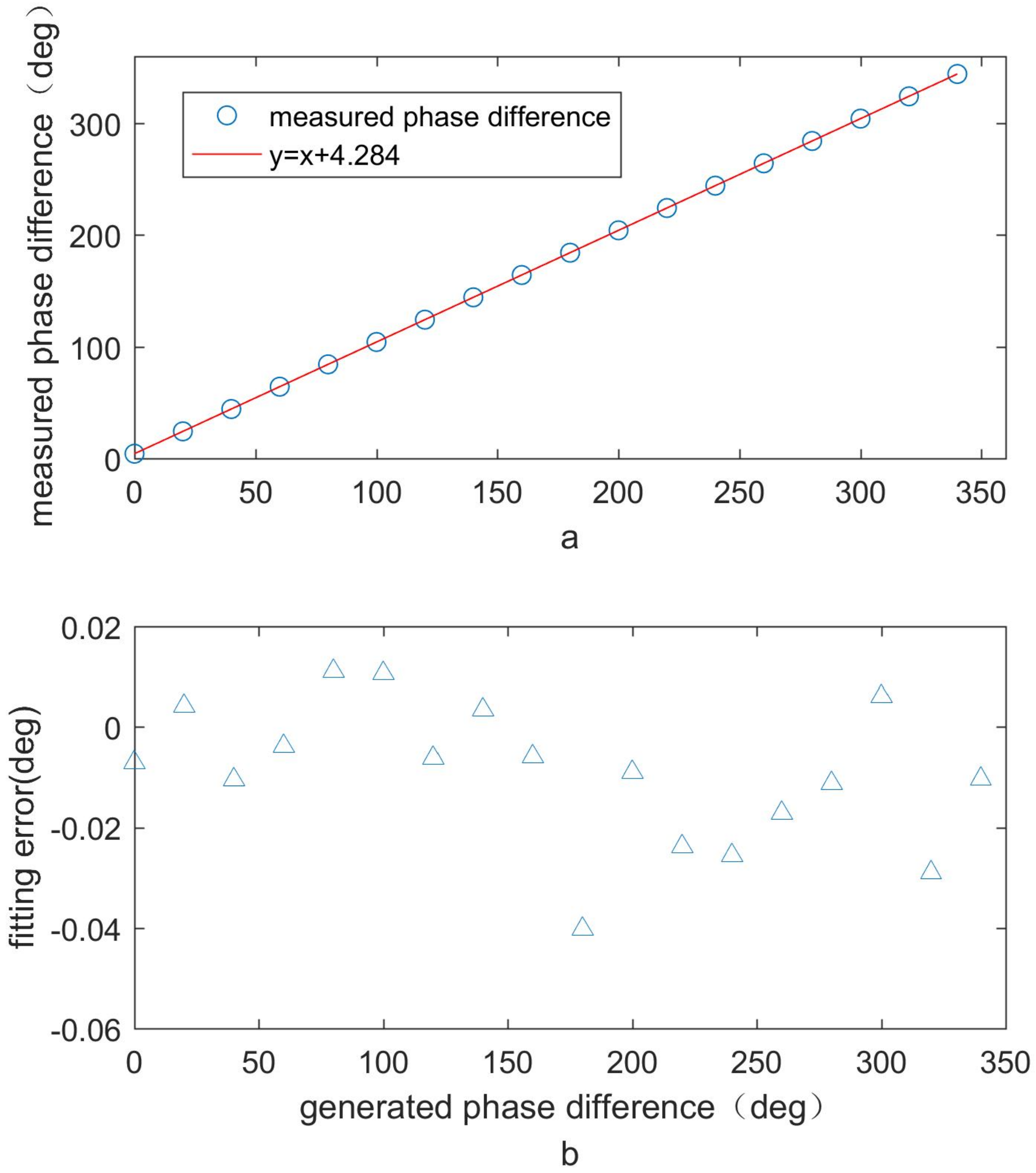
We also tested the linearity of the system. To simulate the delay caused by the transmission distance, we adopted the phase delay function of the two-channel signal generator. The resulting phase delay was for 500 kHz, which is the basic frequency. The system was used to measure the distance of the target and calculate the corresponding phase difference. The recorded experimental data are presented in Table 1, which demonstrates the relationship between the generated and measured phase differences. The variations of measured phase differences and the fitting errors are shown in Figure 9a,b. The measured phase shift is proportional to the generated phase shift, which can be fitted by the function y = x + 4.238 ; the fitted RMSE is 0 . 01317 ° . As shown in Figure 9b, the fitting error is less than 0.04 ° . The constant 4.238 is the phase difference caused by the difference in delay between the two channels, which is the l R F value in Equation (2). In practice, to obtain the phase difference of the target distance, it is necessary to subtract the phase delay from the measured phase difference The simulation demonstrated that the system has good linearity for the entire measuring range.
Finally, the variation in the ranging RMSE with the SNR changes was tested. First, the relationship between SNR and P s was calibrated. In the case of P s = 0 , the noise power of the detector was 6.59 × 10 4 W. When the optical signal power was −20 dBm, the sum of the output signals and the noise power of the detector was 0.2935 W. Therefore, the SNR was determined to be 53 dB when the optical signal power was −20 dBm. When the input optical power was −40 dBm under various attenuation conditions, the detector signal and that produced by the signal generator were acquired to calculate the distance. The measured distance delay was that caused by the attenuator. The experimental results demonstrate that the range was approximately 4.18 m. The ranging precision was determined, and the experimental data are recorded in Table 2.
Figure 10 compares the simulation and experimental results of the ranging RMSE varying with the SNR. The experimental and simulated results are apparently in agreement. When the optical signal power was −52 dBm and the SNR was 20 dB, the ranging RMSE was 1 cm.

4. Discussion and Conclusions

This study introduces a phase-shift laser ranging technology based on multi-frequency carrier phase modulation. First, we derived the equations for the demodulated signal and calculated the distance of the target and velocity of the signal. Next, we conducted a series of simulations to analyze the influence of the stagger coefficient, modulation depth, and SNR on the ranging precision. Subsequently, the linearity of the system was tested and was found to be satisfactory in the entire range; the linear fitting error was 0.01317 ° RMSE. Compared to the single frequency phase-shift laser range finder [20], the phase error did not increase significantly at 180 ° . Finally, we conducted an experiment in which the ranging precision of the system varied with its SNR. The experimental results were consistent with the simulation results, which proved that the proposed discriminative fast demodulation algorithm was feasible. A ranging precision of 1 cm was achieved with an SNR of 20 dB, which is a major improvement compared to our previous study owing to the fact that the phase measuring RMSE was 0.0019 ° in this study whereas it was 0.22 ° in the previous study [6]. Meanwhile, the results demonstrated that the technology was robust. As shown in Figure 10, the ranging RMSE was 0.09 m when the SNR was only 1 dB. These results demonstrate that a phase-shift laser ranging technology based on multi-frequency carrier phase modulation can achieve high-precision measurements over a wide range.
The technology can also simultaneously measure distance and velocity [21,22]. In future studies, we will analyze the influence of introducing multi-frequency modulation on the velocity measurement ability and conduct experiments to measure moving targets.

Author Contributions

Conceptualization, L.Z. and H.H.; methodology, H.H. and J.S.; formal analysis, L.Z. and H.H.; writing—original draft preparation, L.Z. and H.H.; writing—review and editing, J.S. and B.L.; supervision, B.L. All authors have read and agreed to the published version of the manuscript.

Funding

This work was supported in part by the National Key R&D Program of China under grant number 2020YFB0408302.

Institutional Review Board Statement

Not applicable.

Informed Consent Statement

Not applicable.

Data Availability Statement

Not applicable.

Conflicts of Interest

The authors declare no conflict of interest.

References

  1. Jiang, C.; Yang, J.; Zhang, L.; Wang, X. High-precision phase-shift laser range finder system based on laser beat-frequency. Acta Photonica Sin. 2014, 43, 912006. [Google Scholar] [CrossRef]
  2. Ran, Y.; Gaofei, Z.; Zichen, Z.; Zheng, Y. Design and experiment of a laser ranging scheme for aerospace applications. Infrared Laser Eng. 2014, 43, 700–706. [Google Scholar]
  3. Song, H.; Zhang, Y.; Wu, C.; Yichun, S.; Wu, C.; Guo, Y.; Huang, H.; Si, Y.; Yang, P.; Quan, X. Calibration method 191 of underwater phase laser ranging. Infrared Laser Eng. 2019, 48, 406008. [Google Scholar] [CrossRef]
  4. Yoon, H.; Hong, J.; Kim, H.; Park, K. A characteristic analysis of the laser range finder with various modulation frequencies. In Proceedings of the 2008 International Conference on Control, Automation and Systems, Seoul, Korea, 14–17 October 2008; pp. 2280–2283. [Google Scholar] [CrossRef]
  5. He, H.; Sun, J.; Lu, Z.; Xu, M.; Lao, C.; Han, R.; Cai, X.; Li, Y. Phase-shift laser range finder technique based on optical carrier phase modulation. Appl. Opt. 2020, 59, 5079–5085. [Google Scholar] [CrossRef] [PubMed]
  6. He, H.; Sun, J.; Lu, z.; Cong, H.; Han, R.; Ren, W.; Zhang, L.; Li, C.; Jiang, Y. Outdoor Experiments of Phase-Shift Laser Range Finder Technique Based on Optical Carrier Phase Modulation. Chin. J. Lasers 2021, 48, 2404001. [Google Scholar] [CrossRef]
  7. Zhen, D.; Chen, W.; Chen, L. A laser ranging method with high precision and large range in high speed based on phase measurement. J. Optoelectron. Laser 2015, 2, 303–308. [Google Scholar] [CrossRef]
  8. Liu, X.; Wang, L.; Tang, X.; Li, S.; Ma, C.; Yang, Y.; Jiang, X.; Huang, C.; Wang, X.; Pan, S. Optical Transfer Delay Measurement Based on Multi-frequency Phase-Derived Ranging. In Proceedings of the 2021 19th International Conference on Optical Communications and Networks (ICOCN), Qufu, China, 23–27 August 2021; pp. 1–6. [Google Scholar] [CrossRef]
  9. Yoon, H.; Hong, J.; Kang, S.; Park, K. A multiple phase demodulation method for high resolution of the laser range finder. In Proceedings of the 2008 3rd International Conference on Sensing Technology, Taipei, Taiwan, 30 November–3 December 2008; pp. 324–328. [Google Scholar] [CrossRef]
  10. Den Boef, A.J. Two-wavelength scanning spot interferometer using single-frequency diode lasers. Appl. Opt. 1988, 27, 306–311. [Google Scholar] [CrossRef] [PubMed]
  11. Williams, C.C.; Wickramasinghe, H.K. Optical ranging by wavelength multiplexed interferometry. J. Appl. Phys. 1986, 60, 1900–1903. [Google Scholar] [CrossRef]
  12. Xu, B.J.; Li, G.; Huangfu, K. Ambiguity problem of digitized multiple frequency CW ranging radar under noisy condition. Acta Electonica Sin. 2002, 30, 903. [Google Scholar]
  13. Jia, F.; Ding, Z.; Yuan, F.; Ge, D. Real-time laser range finding system for moving target based on all-phase fourier transfrorm spectrum analysis. Acta Opt. Sin. 2010, 30, 2928–2934. [Google Scholar] [CrossRef]
  14. Zhang, S.; Chen, H.; Gong, G.; Shi, J.; Nei, H.; Wang, Y.; Bu, X. Research on Phase Difference Laser Ranging System. In Proceedings of the 2018 2nd IEEE Advanced Information Management, Communicates, Electronic and Automation Control Conference (IMCEC), Xi’an, China, 25–27 May 2018; pp. 1776–1782. [Google Scholar] [CrossRef]
  15. Le, Y.; Xu, X.; Li, Z.; Zhao, Y.; Xu, F. Resolution method of laser ranging ambiguity based on overdetermined equations. Chin. J. Sci. Instrum. 2012, 33, 930–935. [Google Scholar] [CrossRef]
  16. Yuan, Q.P.; Fan, L.J.; Tong, Z.R. Research on Tri-Frequency Phase Ranging Method. Mech. Electron. Eng. III 2012, 130, 2957–2960. [Google Scholar] [CrossRef]
  17. Jurna, M.; Korterik, J.; Otto, C.; Offerhaus, H. Shot noise limited heterodyne detection of CARS signals. Opt. Express 2007, 15, 15207–15213. [Google Scholar] [CrossRef] [PubMed]
  18. McManamon, P. Review of ladar: A historic, yet emerging, sensor technology with rich phenomenology. Opt. Eng. 2012, 51, 060901. [Google Scholar] [CrossRef]
  19. Lyons, R. Digital Envelope Detection: The Good, the Bad, and the Ugly [Tips and Tricks]. IEEE Signal Process. Mag. 2017, 34, 183–187. [Google Scholar] [CrossRef]
  20. Liu, Y.Z.; Zhao, B. Phase-shift correlation method for accurate phase difference estimation in range finder. Appl. Opt. 2015, 54, 3470–3477. [Google Scholar] [CrossRef] [PubMed]
  21. Karlsson, C.J.; Olsson, F.Å.A.; Letalick, D.; Harris, M. All-fiber multifunction continuous-wave coherent laser radar at 1.55 µm for range, speed, vibration, and wind measurements. Appl. Opt. 2000, 39, 3716–3726. [Google Scholar] [CrossRef] [PubMed]
  22. Yang, F.; He, Y.; Shang, J.; Chen, W. Development of an all-fiber heterodyne lidar for range and velocity measurements. Chin. Opt. Lett. 2010, 8, 713–716. [Google Scholar] [CrossRef] [Green Version]
Figure 1. Diagram of the phase-shift laser ranging system based on multi-frequency carrier phase modulation.
Photonics 09 00603 g001
Figure 2. (a) Variation in the ranging RMSE; (b) variation in the phase measuring of RMSE (with SNR under different stagger coefficients).
Photonics 09 00603 g002
Figure 3. Variation in the ranging RMSE with the modulation depths at different SNRs.
Photonics 09 00603 g003
Figure 4. Variation in the ranging RMSE at various SNRs for single and triple frequencies.
Photonics 09 00603 g004
Figure 5. Photo of the experimental devices.
Photonics 09 00603 g005
Figure 6. Spectra of the detector output signal and its peak.
Photonics 09 00603 g006
Figure 7. Signal demodulation process: (a) collected balance detector signal, (b) differential signal, (c) envelope detection signal.
Photonics 09 00603 g007
Figure 8. Spectra of the modulated and demodulated signals.
Photonics 09 00603 g008
Figure 9. Variation of the (a) measured phase difference @500 kHz and (b) fitting error with the generated phase difference.
Photonics 09 00603 g009
Figure 10. Simulation and experimental results of the ranging RMSE varying with the SNR.
Photonics 09 00603 g010
Table 1. Generated and measured phase differences ( ° ).
Generated Phase Difference ( ° )Measured Distance (m)Measured Phase Difference ( ° )
03.5644.277
2020.24024.288
4036.89544.273
6053.56764.280
8070.24684.295
10086.912104.295
120103.565124.278
140120.240144.287
160136.898164.278
180153.537184.244
200170.229204.275
220186.883224.260
240203.549244.258
260220.222264.267
280236.894284.273
300253.575304.290
320270.213324.255
340286.895344.274
Table 2. Ranging precision under different powers of signal light conditions.
Attenuation (dB)Optical Power (dBm)SNR (dB)Ranging Precision (m)
10−50230.0061
11−51220.0073
12−52210.0091
13−53200.0105
14−54190.0096
15−55180.0108
16−56170.0134
17−57160.0138
18−58150.0135
19−59140.0155
20−60130.0190
21−61120.0177
22−62110.0220
23−63100.0282
24−6490.0236
25−6580.0323
26−6670.0380
27−6760.0513
28−6850.0501
29−6940.0568
30−7030.0635
31−7120.0619
32−7210.0930
33−73022.0784
Publisher’s Note: MDPI stays neutral with regard to jurisdictional claims in published maps and institutional affiliations.