Article

Quantum Interference in Spontaneous Decay of a Quantum Emitter Placed in a Dimer of Bismuth-Chalcogenide Microparticles

by
Nikolaos Kyvelos
1,
Georgios Tsigaridas
1,
Emmanuel Paspalakis
2 and
Vassilios Yannopapas
1,*
1
Department of Physics, School of Applied Mathematical and Physical Sciences, National Technical University of Athens, GR-15780 Athens, Greece
2
Department of Materials Science, University of Patras, GR-26504 Patras, Greece
*
Author to whom correspondence should be addressed.
Photonics 2022, 9(9), 596; https://doi.org/10.3390/photonics9090596
Submission received: 22 July 2022 / Revised: 16 August 2022 / Accepted: 19 August 2022 / Published: 23 August 2022
(This article belongs to the Section Quantum Photonics and Technologies)

Abstract

:
We investigate the phenomenon of quantum interference in spontaneous emission for a three-level V-type quantum emitter placed between two bismuth-chalcogenide (Bi 2 Te 3 , Bi 2 Se 3 ) microspheres. In particular, we find that the degree of quantum interference can become as high as 0.994, a value which is attributed to the strong dependence of the spontaneous emission rate on the orientation of an atomic dipole relative to the surfaces of the microspheres, at the excitation frequencies of phonon-polariton states of the bismuth-chalcogenide microspheres (anisotropic Purcell effect). As a consequence of the high degree of quantum interference, we observe the occurrence of strong population trapping in the quantum emitter. To the best of our knowledge, the reported values of the degree of quantum interference are record values and are obtained for a relatively simple geometrical setup such as that of a microparticle dimer.

1. Introduction

Quantum technologies based on nanophotonic devices rely on strong interaction between a quantum emitter (QE) and light. This interaction can be enhanced by coupling emitters to a nanophotonic structure (environment) that enhances the corresponding emission rates by increasing the local density of states (LDOS) available to the QE, also known as the Purcell effect. Since Purcell’s analysis in 1946 [1], it has been realized that spontaneous emission (SE) of QEs, such as atoms, molecules and quantum dots, is not a radiative intrinsic property of the emitters but it is modified by the environment in which the QE is embedded [2,3]. The Purcell factor F p , i.e., the SE rate in the presence of a photonic environment relative to the SE rate in vacuum, is a key quantity in cavity quantum electrodynamics (QED) that quantifies the coupling rate between a QE and a cavity mode. Although SE is a quantum mechanical phenomenon caused by vacuum-field fluctuations, the modification of the SE rate can be described classically (Maxwell’s equations) [4]. The radiation originally produced by a QE, is scattered off the photonic environment (nearby objects) of the QE and arrives back at the emitter position, enhancing or suppressing the SE rate. In order to achieve significant increase in the SE rate we need an optical resonator that stores light in a volume as small as possible, for as long as possible. In cavity QED, the light-matter interactions depend on characteristic features of the nanostructure, such as the material composition, size and geometry as well as on the radiation field. Examples of photonic micro- and nanostructures that modify spontaneous decay include microwave and optical cavities, photonic crystals [5], refractive index metamaterials [6], semiconductor microcavities, two-dimensional structured reservoirs [7] and plasmonic nanostructures [8,9,10,11,12,13,14,15].
Recently, a new category of materials has emerged, namely bismuth chalcogenides such as Bi 2 Se 3 and Bi 2 Te 3 , whose dielectric function possesses colossal values [16,17] due to the presence of strong phonon resonances in the THz regime which induce high field enhancement and strong confinement of light at their surfaces [18]. In noble-metal nanostructures, the Purcell enhancement reaches high values thanks to the plasmon resonances, but the coupling with QEs in their proximity is less efficient due to the large ohmic losses [19]. On the other hand, bismuth chalgonides exhibit a high field enhancement in the THz due to polaritonic excitations, but combined with significantly lower ohmic losses, they lead to much more efficient coupling with QEs [20,21]. These polaritonic excitations are eigenstates of the electromagnetic (EM) field and, as such, the mismatch between the low density of EM modes in free space and the high density of polaritonic modes in the bismuth chalcogenides produces a large LDOS around the bismuth chalcogenides particles. The high LDOS, in turn, produces a strong modification and control over the SE rate of a nearby QE. In our case the available EM modes are affected not only by the position and the emission frequency of QE, but also by the orientation of the dipole moment. Therefore, the SE rate Γ of a dipole emitter is governed by the partial local density of states (PLDOS) [22].
Quantum interference (QI) is a phenomenon which arises from the SE of two nearly-degenerate excited states of a QE to a common ground state in a manner that allows the interference between the two SE channels. The spectrum of the SE strongly depends on the energy-level structure as well as on the emerging quantum coherence; however, for the interference effects to occur, the transition dipole moments of the two SE paths should be nonorthogonal. This condition is difficult to met in pure quantum systems. In 2000, Agarwal [23] showed that the presence of anisotropy in the quantum vacuum can lead to QI between the decay channels of close lying states [24]. Namely, when the difference in the spontaneous decay rates for orthogonal dipole moments is large, an observable degree of QI emerges [25]. The phenomenon of QI in a QE may lead to exciting phenomena in quantum optics, such as coherent population trapping [26,27,28], high degrees of entanglement [29,30,31], lasing without inversion [32,33], ultra-narrowspectral lines and controlled emission in resonance fluorescence spectra [24,34,35], optical transparency with slow light [36,37], gain without inversion [38], enhanced Kerr nonlinearity [39,40,41,42,43].
In this work, we present results for the spontaneous emission and the degree of QI for a V-type three-level QE located at the center of a dimer of bismuth-chalcogenide microspheres separated by a nanoscale gap. First, we evaluate the Purcell factor of the QE as a function of frequency for different gap distances between the QE and the microparticles. Then, we show that this microstructure setup, for various frequencies in the terahertz regime, supports very high values of the degree of QI (very close to the theoretical maximum value of unity) which are record values, to the best of our knowledge. The occurrence of such high degree of QI leads to strong population trapping [28] in the QE, even for large distances between the microparticles and the QE.

2. Quantum Interference in a V-Type Quantum Emitter

In Figure 1 we depict a V-type three-level system [33] which represents a generic model of QE. We consider a V-type model with two degenerate Zeeman sublevels | 2 and | 3 and a single ground state | 1 . We assume that excited levels can decay to the ground state by spontaneous emission, whereas a direct transition between excited levels is not allowed.
The atomic dipole-moment operator is taken as
d = d ( | 2 1 | ε ^ + | 3 1 | ε ^ + ) + H . c .
where
ε ^ ± = 1 / 2 ( e z ± i e x )
describe the right-rotating ( ε ^ + ) and left-rotating ( ε ^ ) unit vectors, and d is real, corresponding to the magnitude of the atomic dipole moment. We assume that both excited levels | 2 and | 3 decay spontaneously to the ground level but with different decay rates 2 γ 2 , 2 γ 3 , respectively. The spontaneous decay dynamics of the system are studied by a density-matrix approach. By restricting our study exclusively to spontaneous-emission effects and considering the rotating-wave and Wigner–Weisskopf approximations, the time-dependent equations modeling the interaction of the QE with its photonic environment are written as [10,11] (we take = 1):
ρ 22 ˙ = 2 γ 2 ρ 22 κ 3 ρ 23 κ 3 ρ 32 ,
ρ 33 ˙ = 2 γ 3 ρ 33 κ 2 ρ 32 κ 2 ρ 23 ,
ρ 23 ˙ = ( γ 2 + γ 3 ) ρ 23 κ 2 ρ 22 κ 3 ρ 33 ,
with
ρ 11 + ρ 22 + ρ 33 = 1
and
ρ n m = ρ m n * .
The terms κ 1 and κ 2 are responsible for the interference between the two decay channels. The presence of high anisotropy in the photonic environment leads to strong interferences, which means that the κ ’s are comparable to the γ ’s. We assume that the orientation of the QE dipoles for the transitions | 2 | 1 and | 3 | 1 are defined in terms of a nearby material surface. In this case, the spontaneous-emission rates are provided by [10,11]
γ 2 , 3 = 1 2 d 2 ω 2 , 3 2 Im [ G ( r , r ; ω 2 , 3 ) + G ( r , r ; ω 2 , 3 ) ]
where ⊥ (‖) refers to a dipole-oriented normal (parallel) to the material surface, and ω 2 , 3 is the transition frequency for each transition channel. Furthermore, r is the position of the QE and d is the corresponding dipole moment. G ( ) ( r , r ; ω 2 , 3 ) are the respective components of the dyadic EM Green’s tensor [44,45] of the surrounding environment. The coefficients κ 2 and κ 3 represent the QI between the two spontaneous-emission channels | 2 | 1 and | 3 | 1 and they read as [10,11]
κ 2 , 3 = 1 2 d 2 ω 2 , 3 2 Im [ G ( r , r ; ω 2 , 3 ) G ( r , r ; ω 2 , 3 ) ] .
To simplify things, we assume that the two upper levels | 2 and | 3 are almost degenerate, i.e., ω 2 ω 3 = ω 0 . In this case,
γ 2 γ 3 = γ = 1 2 ( Γ + Γ )
and
κ 2 κ 3 = κ = 1 2 ( Γ Γ ) ,
where we define the SE rates normal and parallel to the surface as
Γ = d 2 ω 0 2 Im [ G ( r , r ; ω 0 ) ]
and
Γ = d 2 ω 0 2 Im [ G ( r , r ; ω 0 ) ] .
The degree of QI is defined as
p = ( Γ Γ ) ( Γ + Γ ) .
When the difference in the decay rates between the radial and tangential orientation of the SE dipole moment is large, the degree of quantum interference will be enhanced. Obviously, for p = 1 we have the maximum of QI which, as we will see below, can be approached up to the third decimal digit by placing the QE close to a structure that completely quenches Γ in the weak coupling regime or maximizes the difference Γ Γ in the strong coupling regime, i.e., by placing the QE in the middle of the gap between two bismuth-chalcogenide microspheres.

3. Computational Method

Although spontaneous emission is a quantum-mechanical process, the PLDOS can be calculated classically and depends only on the photonic environment. Namely, we have employed 3D electrodynamic simulations using the finite element method (FEM) [46] via COMSOL Multiphysics software. The simulation domain consists of a dimer of Bi 2 Te 3 ( Bi 2 Se 3 ) microspheres with radius 2 µm, a point source (QE), a region of free space and a perfectly matched layer (PML) eliminating the reflections at the domain boundaries. We study microspheres with radius 2 µm as it was found that the maximization of quantum interference for a single microsphere is achieved for a radius of about 2 µm [21].
The dielectric functions of the materials are described by [17],
ϵ ( ω ) = j = α , β , f ω p j 2 ω 0 j 2 ω 2 i γ j ω .
The subscripts appearing in the sum of Equation (15) stem from contributions of α and β phonons as well as from bulk free-charge carriers f. The corresponding parameters for the three terms appearing in Equation (15) are taken from a fit to experimental data [47] on bulk Bi 2 Te 3 and can be found in the Table 1 of [17]. It is known that Bi 2 Te 3 ( Bi 2 Se 3 ) are topological insulators and their dielectric function contains an additional term that accounts for the surface states and is inversely proportional to the radius of the sphere [18]. It turns out that this term is significant only for nanospheres and is therefore negligible in our case.
In order to calculate the SE rate as well the corresponding Purcell factor for the QE embedded in the gap between the bismuth chalcogenide microspheres, we proceed as follows. Maxwell’s equations in the frequency domain result in the following relation known as Poynting’s theorem:
S S · n d A = 1 2 V R e ( j × E ) d V ,
where S is the time-averaged Poynting vector, and n is an outward pointing normal vector on the closed boundary of V ,   S . Equation (16) states that the power out through S equals the power dissipation inside V due to the current j. In practice, we use this relation to quantify the power radiated by dipoles in different environments by evaluation of either side of this equation. The Purcell factor is obtained as the ratio of the total power emitted by the QE with and without the presence of a certain photonic environment.
The Purcell factor can be determined by integrating the calculated time-averaged Poynting vector over a surface that encloses only the QE and not the boundaries of the cavity or microparticle [47], as
F p = Γ Γ 0 = P P 0 ,
where P is the total power radiated by the QE embedded in a certain photonic environment and P 0 is the radiated power of the QE in free space. In the same manner, Γ is the decay rate of the QE embedded in a photonic environment and Γ 0 is the decay rate of the QE in free space.

4. Results and Discussion

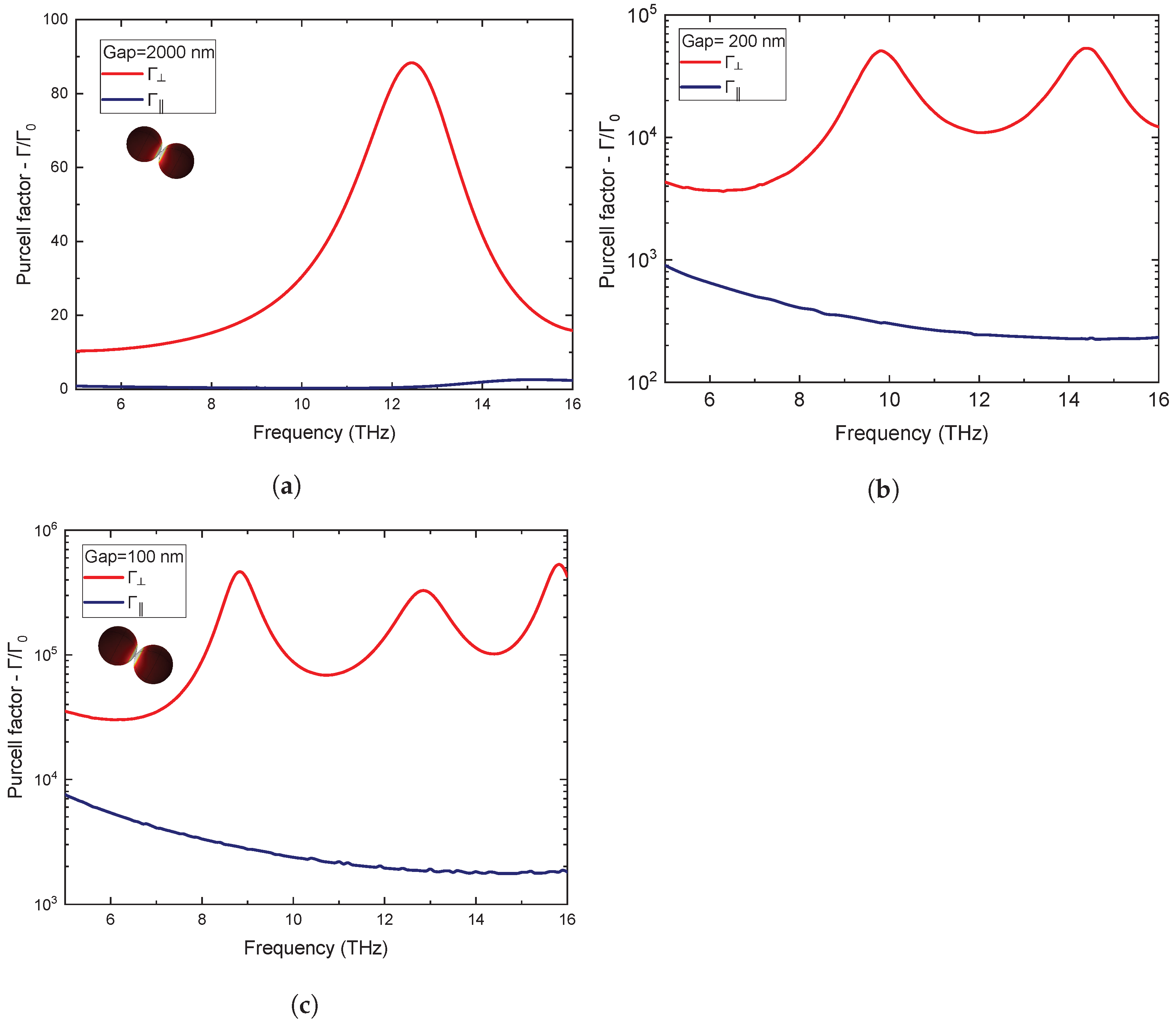
In Figure 2, we present the Purcell enhancement factors in a dimer of Bi 2 Te 3 microspheres for gap distances 4000 nm, 200 nm and 100 nm.
In the above figures, it is observed that the Purcell factor increases when the dipole moment is perpendicular to the surfaces of the microspheres, while it decreases when the dipole moment is parallel to the surfaces. The largest difference in the Purcell factors, for the 4000 nm nanogap, occurs for frequency close to 12.5 THz, where polaritonic resonance takes place and is due to the fact that the corresponding polarization vector of the polaritonic resonance is almost radial. The value of Γ is greatly reduced for frequency 10.4 THz, where the Purcell factor Γ / Γ 0 assumes the value F p = 0.275 . For the smallest nanogaps, 200 nm and 100 nm, the Purcell factor increases rapidly and assumes values in the range of 10 4 10 6 . This is due to the fact that, between the microparticles, there is strong coupling [48,49,50,51] between the vacuum states and the QE states. Namely, due to the presence of the enhanced, polariton-induced fields on the surfaces of the microspheres and due to the reduction in the volume of the cavity created in the space between spheres, the SE photons do not escape quickly in photonic states out of the cavity, thus enhancing the interaction between the emitter states with the polaritonic states of the microspheres.
By reducing the gap between the microspheres, we go from weak coupling to a strong coupling regime between the QE and the photonic environment. At the same time, the number of EM modes within the gap (viewed as a cavity) interacting with the QE increases, which results in the increase in the number of peaks in the spectra of the decay rates. Alternatively, the increase in the number of peaks results in from the Rabi splitting of the hybrid QE-polariton mode as a consequence of entering the strong coupling regime.
We also note that the reason for the emergence of such high values of the Purcell factors, for all gap sizes, is the low ohmic loss rate. The bismuth dichalcogenes absorb a minimal percentage of incident radiation (reflective surfaces) as their dielectric function takes colossal values in the THz region, thus increasing the possibility that the scattered radiation returns to the region of the quantum emitter influencing its decay rate.
According to Equation (14), the QI is expected to be enhanced close to frequencies where there is a maximum reduction in the excitation rate Γ . In Figure 3, it is evident that the degree of QI has very high values for a variety of frequencies.
The degree of QI approaches the maximum value ( p 1 ) for a wide range of frequencies and distances between the microspheres. Especially for the large gap with size 2000 nm, the degree of QI takes a maximum value p = 0.990 at 11.6 THz. For the smallest gaps of 200 nm and 100 nm, the degree of QI in the largest frequency range assumes very high values that range between p = 0.94 and a maximum value p = 0.993 .
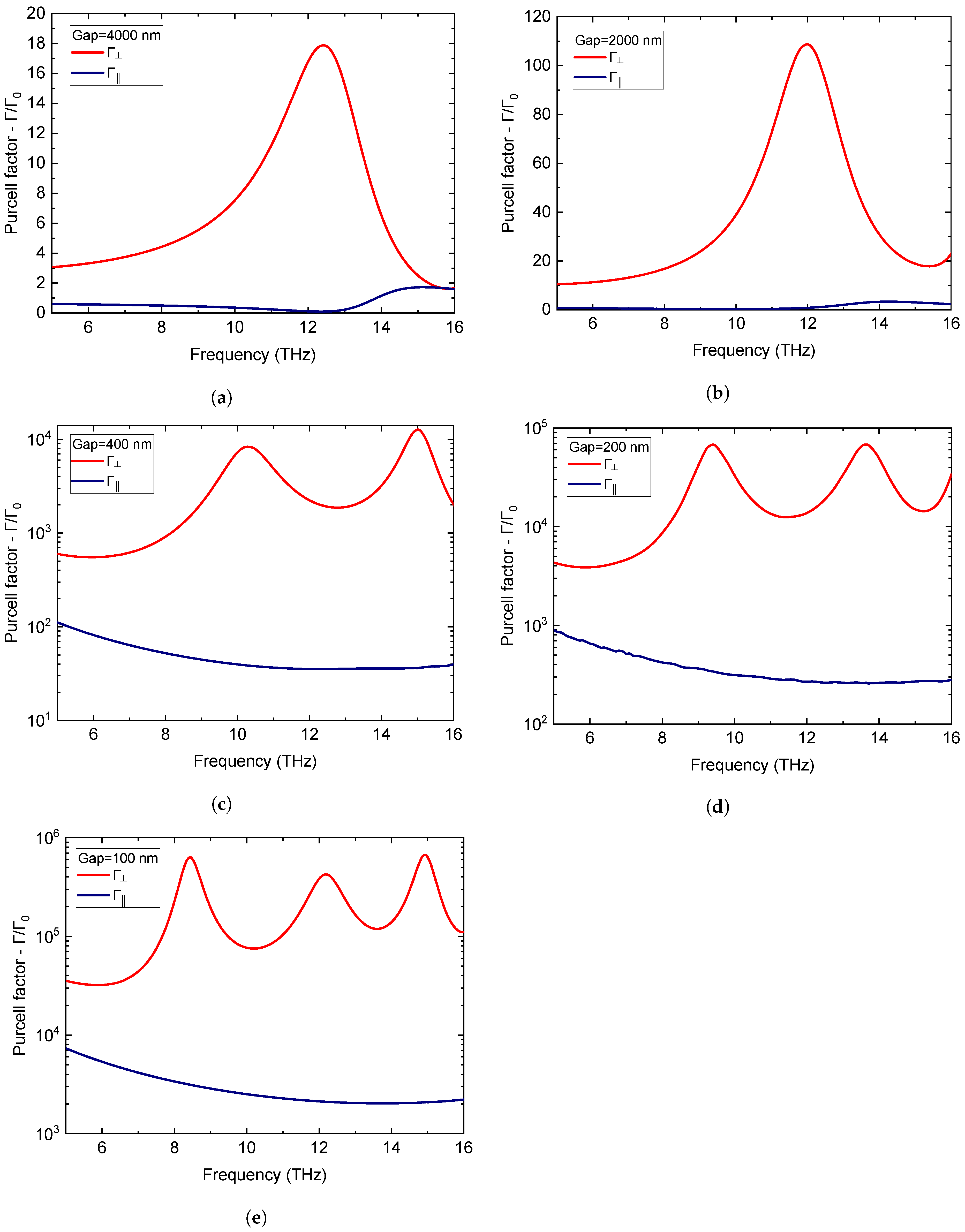
In Figure 4, we show the Purcell factors for a dimer of Bi 2 Se 3 microspheres, for gap distances 4000 nm, 2000 nm, 400 nm, 200 nm and 100 nm.
The Purcell factor, as in the case of Bi 2 Te 3 microspheres, increases for dipole moments with direction perpendicular to the surfaces of the microspheres, while for dipole moments parallel to the surfaces of the microspheres, the Purcell factor decreases. The polaritonic resonances are shifted towards lower frequencies compared to the Bi 2 Te 3 dimer system, because the maximization of the difference between the decay rates Γ , Γ occurs for frequencies close to 12 THz while the decay rate Γ of the QE is much more reduced. Specifically, at frequencies 12.4 THz, 11.2 THz, the Purcell factors Γ Γ 0 take the values F p = 0.098 , F p = 0.440 , for the gaps 4000 nm, 2000 nm, respectively. Bismuth selenium microparticles and bismuth telluride microparticles have a similar spontaneous emission rate range. However, as we can observe from Figure 4 for the bismuth selenium dimer system, we observe higher Purcell factors due to slightly stronger polaritonic resonances, which are shifted to lower frequencies. In Figure 5, we show that the degree of QI in the dimer of Bi 2 Se 3 assumes higher values than Bi 2 Te 3 , being such for a wide range of distances and frequencies. In particular, for gaps with sizes 4000 nm and 2000 nm, the degree of QI takes a maximum value p = 0.989 at 12.4 THz and p = 0.989 at 11.2 THz, respectively. For small gaps with dimensions 400 nm, 200 nm and 100 nm, the degree of QI in the largest frequency range assumes very high values that range from p = 0.94 to a maximum value slightly greater than p = 0.994 .
The occurrence of such high degrees of QI is attributed to the fact that the percentage of ohmic losses (heat losses) in the case of radial dipole moment is minimal, which enhances the available vacuum states in the free space, increasing this way the available photonic states for the QE. In contrast, in the case of tangential dipole moments, the rate of ohmic losses increases and the EM radiation ends up in heat losses. Figure 6 shows the percentage of heat losses of the total emitted radiation for the case of a 4000 nm gap. It is obvious that the large reduction in spontaneous emission rate in Figure 2 for a dipole moment parallel to the surfaces of the spheres, occurs in the frequency range where the ohmic losses are maximum.
From Figure 7, we see that the component of the electric field E z , which has the orientation of a vertical dipole, is stronger in the gap region where QE resides, at the resonant frequencies, which causes an increase in the PLDOS and increases the decay rate of the QE. Furthermore, it is obvious that for a dipole parallel to the surfaces of the microspheres, the electric field component E x , which has the orientation of the dipole, is weaker in the gap region. At the same time, the PLDOS is increased outside the gap region.
The analytical formulas for the populations are solutions of Equations (3)–(7) under the assumptions of Equations (10) and (11),
ρ 22 ( t ) = 1 4 ( e Γ t + e Γ t ) 2
ρ 33 ( t ) = 1 4 ( e Γ t e Γ t ) 2 .
When QI is not present ( p = 0 ) , the population of the state | 2 evolves exponentially with
ρ 22 ( t ) = e ( Γ + Γ ) t
and the state | 3 is not involved in the dynamics, which means
ρ 33 ( t ) = 0 .
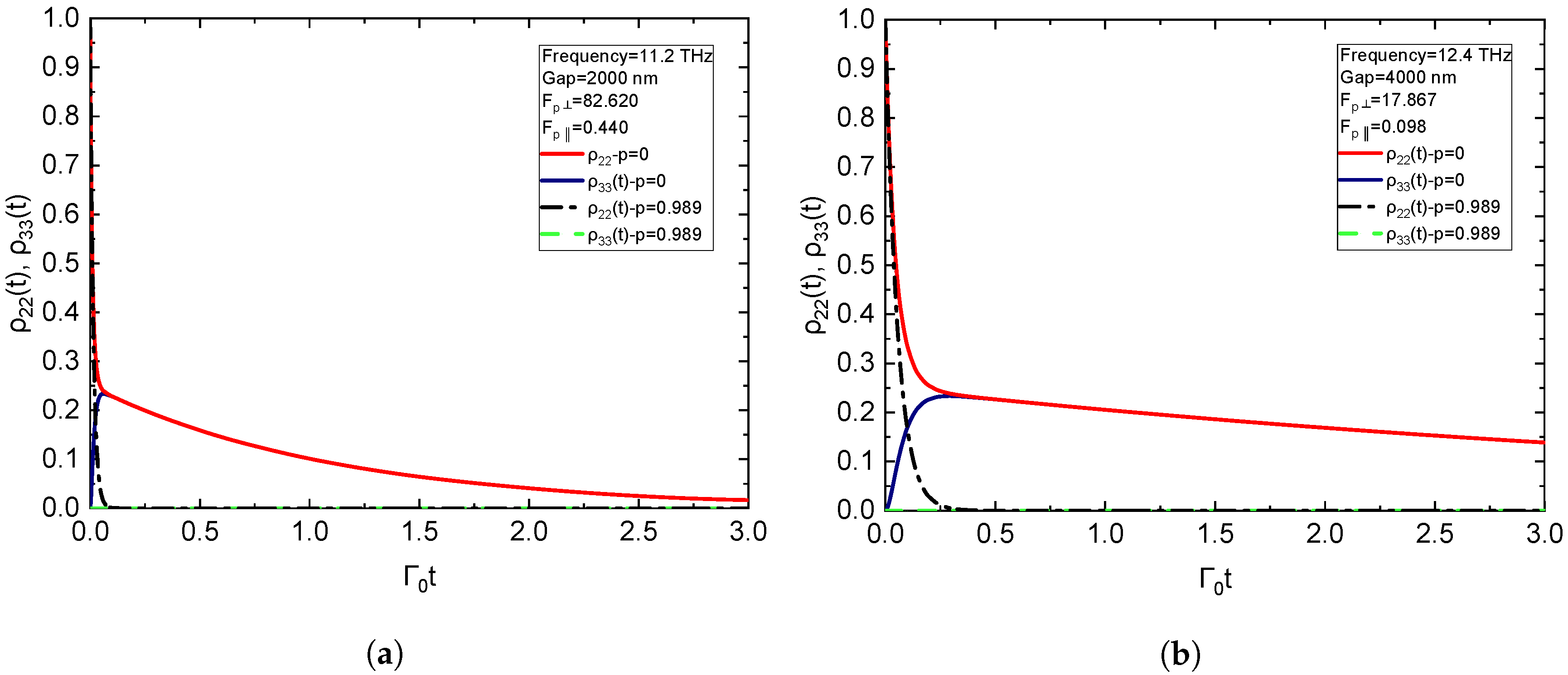
Figure 8 depicts the population dynamics of V-type QE within a dimer of Bi 2 Se 3 for large degrees of QI, assuming that only the state | 2 is initially populated, which means ρ 22 = 1 , ρ 33 = 0 and ρ 23 = 0 . Clearly, when the phenomenon of the QI does not exist, the population decrease for the state | 2 is proportional to the sum of the excitation rates Γ + Γ . Additionally, for p = 0 , the state | 3 is not populated. When the QI is present, the state | 3 becomes populated and the phenomenon of population trapping occurs, in which case the population of the two excited states becomes equal. After trapping their population, the populations of the excited states of the V-type QE are equal at all subsequent times, and their population decreases very slowly as it depends on 2 Γ . In addition, it is observed that the higher the value of Γ Γ 0 , the faster the population trapping occurs. At the same time, the decrease in the population is also prolonged as it follows the slower of Γ , Γ ( Γ in our case), which is also suppressed in the same frequency range.

5. Conclusions

We have investigated the phenomenon of quantum interference in spontaneous emission for a three-level, V-type quantum emitter placed between two bismuth-chalcogenide (Bi 2 Te 3 , Bi 2 Se 3 ) microspheres. In particular, we have demonstrated by rigorous electromagnetic simulations that the degree of quantum interference can become as high as 0.994 at the phonon-polariton frequencies (THz) of bismuth-chalcogenide microspheres, as a result of the strong dependence of the spontaneous emission rate on the orientation of a given atomic dipole relative to the surfaces of the microspheres (anisotropic Purcell effect). The degree of the quantum intereference remains high for a wide range of frequencies in the THz region as well as for a wide range of distances (gap) between the spheres. The high values of the degree of quantum interference promote the emergence of strong population trapping in V-type quantum emitters. To the best of our knowledge, the reported values of the degree of quantum interference are record values and are obtained for a relatively simple geometrical setup such as that of a microparticle dimer.

Author Contributions

Methodology, N.K., V.Y., E.P. and G.T.; software, G.T.; validation, N.K., V.Y., G.T. and E.P.; investigation, N.K., V.Y., G.T. and E.P.; resources, G.T., E.P. and V.Y.; data curation, N.K.; writing—original draft preparation, N.K. and V.Y.; writing—review and editing, N.K., V.Y., G.T. and E.P.; visualization, N.K.; supervision, V.Y. All authors have read and agreed to the published version of the manuscript.

Funding

This research received no external funding.

Institutional Review Board Statement

Not applicable.

Informed Consent Statement

Not applicable.

Conflicts of Interest

The authors declare no conflict of interest.

References

  1. Purcell, E.M. Spontaneous emission probabilities at radio frequencies. Phys. Rev. 1946, 69, 681. [Google Scholar]
  2. Drexhage, K.H. Influence of a dielectric interface on fluorescence decay time. J. Luminesc. 1970, 1, 693–701. [Google Scholar] [CrossRef]
  3. Drexhage, K.H. Interaction of light with monomolecular dye lasers. Prog. Opt. 1974, 12, 163–232. [Google Scholar]
  4. Barnes, W.; Horsley, S.; Vos, W. Classical antennae, quantum emitters, and densities of optical states. J. Opt. 2019, 22, 073501. [Google Scholar] [CrossRef] [Green Version]
  5. Iwase, H.; Englund, D.; Vučković, J. Analysis of the Purcell effect in photonic and plasmonic crystals with losses. Opt. Express 2010, 18, 16546–16560. [Google Scholar] [CrossRef] [PubMed]
  6. Ivanov, K.A.; Morozov, K.M.; Pozina, G.; Gubaydullin, A.R.; Girshova, E.I.; Kaliteevski, M.A. Control of the surface plasmon dispersion and Purcell effect at the metamaterial-dielectric interface. Sci. Rep. 2020, 10, 20828. [Google Scholar]
  7. Adl, H.P.; Gorji, S.; Habil, M.K.; Suárez, I.; Chirvony, V.S.; Gualdrón-Reyes, A.F.; Mora-Seró, I.; Valencia, L.M.; de la Mata, M.; Hernández-Saz, J.; et al. Purcell Enhancement and Wavelength Shift of Emitted Light by CsPbI3 Perovskite Nanocrystals Coupled to Hyperbolic Metamaterials. ACS Photonics 2020, 7, 3152–3160. [Google Scholar] [CrossRef]
  8. Karanikolas, V.; Paspalakis, E. Plasmon-induced quantum interference near carbon nanostructures. J. Phys. Chem. C 2018, 122, 1478. [Google Scholar] [CrossRef]
  9. Yannopapas, V.; Vitanov, N.V. Spontaneous emission of two-level atoms placed within clusters of metallic nanoparticles. J. Phys. Cond. Matter 2007, 19, 096210. [Google Scholar] [CrossRef]
  10. Yannopapas, V.; Paspalakis, E.; Vitanov, N.V. Plasmon-induced enhancement of quantum interference near metallic nanostructures. Phys. Rev. Lett. 2009, 103, 063602. [Google Scholar] [CrossRef]
  11. Evangelou, S.; Yannopapas, V.; Paspalakis, E. Simulating quantum interference in spontaneous decay near plasmonic nanostructures: Population dynamics. Phys. Rev. A 2011, 83, 055805. [Google Scholar] [CrossRef]
  12. Evangelou, S.; Yannopapas, V.; Paspalakis, E. Modifying free-space spontaneous emission near a plasmonic nanostructure. Phys. Rev. A 2011, 83, 023819. [Google Scholar] [CrossRef]
  13. Tame, M.; McEnery, K.; Özdemir, Ş.; Lee, J.; Maier, S.A.; Kim, M.S. Quantum plasmonics. Nat. Phys. 2013, 9, 329–340. [Google Scholar] [CrossRef] [Green Version]
  14. Chikkaraddy, R.; de Nijs, B.; Benz, F.; Barrow, S.J.; Scherman, O.A.; Rosta, E.; Demetriadou, A.; Fox, P.; Hess, O.; Baumberg, J.J. Single-molecule strong coupling at room temperature in plasmonic nanocavities. Nature 2016, 535, 127–130. [Google Scholar] [CrossRef] [Green Version]
  15. Gonçalves, P.; Christensen, T.; Rivera, N.; Jauho, A.P.; Mortensen, N.A.; Soljačić, M. Plasmon-emitter interactions at the nanoscale. Nat. Commun. 2020, 11, 366. [Google Scholar] [CrossRef] [Green Version]
  16. Dubroka, A.; Caha, O.; Hroncek, M.; Friš, P.; Orlita, M.; Holý, V.; Steiner, H.; Bauer, G.; Springholz, G.; Humlicek, J. Interband absorption edge in the topological Bi(Te1−xSex)3. Phys. Rev. B 2017, 96, 235202. [Google Scholar] [CrossRef] [Green Version]
  17. Rider, M.S.; Sokolikova, M.; Hanham, S.M.; Navarro-Cia, M.; Haynes, P.D.; Lee, D.K.K.; Daniele, M.; Guidi, M.C.; Mattevi, C.; Lupi, S.; et al. Experimental signature of a topological quantum dot. Nanoscale 2020, 12, 22817–22825. [Google Scholar] [CrossRef]
  18. Siroki, G.; Lee, D.; Haynes, P. Single-electron induced surface plasmons on a topological nanoparticle. Nat. Commun. 2016, 7, 12375. [Google Scholar] [CrossRef] [Green Version]
  19. Colas des Francs, G.; Barthes, J.; Bouhelier, A.; Weeber, J.C.; Dereux, A.; Cuche, A.; Girard, C. Plasmonic Purcell factor and coupling efficiency to surface plasmons. Implications for addressing and controlling optical nanosources. J. Opt. 2016, 18, 094005. [Google Scholar] [CrossRef] [Green Version]
  20. Chatzidakis, G.D.; Yannopapas, V. Strong electromagnetic coupling in dimers of topological-insulator nanoparticles and quantum emitters. Phys. Rev. B 2020, 101, 165410. [Google Scholar] [CrossRef]
  21. Karaoulanis, D.; Paspalakis, E.; Yannopapas, V. Quantum interference near bismuth-chalcogenide microstructures. J. Opt. Soc. Am. B 2021, 38, 3301–3308. [Google Scholar] [CrossRef]
  22. Vladimirova, Y.V.; Zadkov, V.N. Quantum Optics in Nanostructures. Nanomaterials 2021, 11, 1919. [Google Scholar] [CrossRef] [PubMed]
  23. Agarwal, G.S. Anisotropic Vacuum-Induced Interference in Decay Channels. Phys. Rev. Lett. 2000, 84, 5500–5503. [Google Scholar] [CrossRef] [PubMed] [Green Version]
  24. Paspalakis, E.; Keitel, C.H.; Knight, P.L. Fluorescence control through multiple interference mechanisms. Phys. Rev. A 1998, 58, 4868. [Google Scholar] [CrossRef] [Green Version]
  25. Ficek, Z.; Swain, S. Simulating quantum interference in a three-level system with perpendicular transition dipole moments. Phys. Rev. A 2004, 69, 023401. [Google Scholar] [CrossRef] [Green Version]
  26. Zhu, S.-Y.; Scully, M.O. Spectral line elimination and spontaneous emission cancellation via quantum interference. Phys. Rev. Lett. 1996, 76, 388–391. [Google Scholar] [CrossRef]
  27. Menon, S.; Agarwal, G.S. Gain components in the Autler-Townes doublet from quantum interferences in decay channels. Phys. Rev. A 1999, 61, 013807. [Google Scholar] [CrossRef] [Green Version]
  28. Hughes, S.; Agarwal, G.S. Anisotropy-Induced Quantum Interference and Population Trapping between Orthogonal Quantum Dot Exciton States in Semiconductor Cavity Systems. Phys. Rev. Lett. 2017, 118, 063601. [Google Scholar] [CrossRef] [Green Version]
  29. Das, S.; Agarwal, G.S. Protecting bipartite entanglement by quantum interferences. Phys. Rev. A 2010, 81, 052341. [Google Scholar] [CrossRef] [Green Version]
  30. Iliopoulos, N.; Terzis, A.F.; Yannopapas, V.; Paspalakis, E. Prolonging entanglement dynamics near periodic plasmonic nanostructures. Phys. Rev. B 2017, 96, 075405. [Google Scholar] [CrossRef]
  31. Sangshekan, B.; Sahrai, M.; Asadpour, S.H. Controllable atom-photon entanglement via quantum interference near plasmonic nanostructure. Sci. Rep. 2022, 12, 677. [Google Scholar] [CrossRef] [PubMed]
  32. Zhou, P.; Swain, S. Quantum interference in probe absorption: Narrow resonances, transparency, and gain without population inversion. Phys. Rev. Lett. 1997, 78, 832–835. [Google Scholar] [CrossRef]
  33. Paspalakis, E.; Gong, S.-Q.; Knight, P.L. Spontaneous emission induced coherent effects in absorption and dispersion of a V-type three-level atom. Opt. Commun. 1998, 152, 293–298. [Google Scholar] [CrossRef]
  34. Zhou, P.; Swain, S. Ultranarrow spectral lines via quantum interference. Phys. Rev. Lett. 1996, 77, 3995. [Google Scholar] [CrossRef]
  35. Wang, C.-L.; Kang, Z.-H.; Tian, S.-C.; Jiang, Y.; Gao, J.-Y. Effect of spontaneously generated coherence on absorption in a V-type system: Investigation in dressed states. Phys. Rev. A 2009, 79, 043810. [Google Scholar] [CrossRef]
  36. Evangelou, S.; Yannopapas, V.; Paspalakis, E. Transparency and slow light in a four-level quantum system near a plasmonic nanostructure. Phys. Rev. A 2012, 86, 053811. [Google Scholar] [CrossRef]
  37. Li, L.; Nie, W.; Chen, A. Transparency and tunable slow and fast light in a nonlinear optomechanical cavity. Sci. Rep. 2016, 6, 35090. [Google Scholar] [CrossRef] [Green Version]
  38. Frogley, M.D.; Dynes, J.F.; Beck, M.; Faist, J.; Phillips, C.C. Gain without inversion in semiconductor nanostructures. Nat. Mater 2006, 5, 175–178. [Google Scholar] [CrossRef]
  39. Paspalakis, E.; Kylstra, N.J.; Knight, P.L. Transparency induced via decay interference. Phys. Rev. Lett. 1999, 82, 2079. [Google Scholar] [CrossRef] [Green Version]
  40. Bortman-Arbiv, D.; Wilson-Gordon, A.D.; Friedmann, H. Phase control of group velocity: From subluminal to superluminal light propagation. Phys. Rev. A 2001, 63, 043818. [Google Scholar] [CrossRef]
  41. Gurudev Dutt, M.V.; Cheng, J.; Li, B.; Xu, X.; Li, X.; Berman, P.R.; Steel, D.G.; Bracker, A.S.; Gammon, D.; Economou, S.E.; et al. Stimulated and spontaneous optical generation of electron spin coherence in charged GaAs quantum dots. Phys. Rev. Lett. 2005, 94, 227403. [Google Scholar] [CrossRef] [Green Version]
  42. Niu, Y.-P.; Gong, S.-Q. Enhancing Kerr nonlinearity via spontaneously generated coherence. Phys. Rev. A 2006, 73, 053811. [Google Scholar] [CrossRef]
  43. Asadpour, S.H.; Sahrai, M.; Soltani, A.; Hamedi, H.R. Enhanced Kerr nonlinearity via quantum interference from spontaneous emission. Phys. Lett. A 2012, 376, 147–152. [Google Scholar] [CrossRef]
  44. Yannopapas, V.; Vitanov, N.V. Electromagnetic Green’s tensor and local density of states calculations for collections of spherical scatterers. Phys. Rev. B 2007, 75, 115124. [Google Scholar] [CrossRef]
  45. Rosolen, G.; Maes, B.; Chen, P.Y.; Sivan, Y. Overcoming the bottleneck for quantum computations of complex nanophotonic structures: Purcell and Förster resonant energy transfer calculations using a rigorous mode-hybridization method. Phys. Rev. B. 2020, 101, 155401. [Google Scholar] [CrossRef] [Green Version]
  46. Gallinet, B.; Butet, J.; Martin, O.J. Numerical methods for nanophotonics: Standard problems and future challenges. Laser Photonics Rev. 2015, 9, 577–603. [Google Scholar] [CrossRef]
  47. Pelton, M. Modified spontaneous emission in nanophotonic structures. Nat. Photon. 2015, 9, 427–435. [Google Scholar] [CrossRef]
  48. Thanopulos, I.; Yannopapas, V.; Paspalakis, E. Non-Markovian dynamics in plasmon-induced spontaneous emission interference. Phys. Rev. B 2017, 95, 075412. [Google Scholar] [CrossRef] [Green Version]
  49. Leng, H.; Szychowski, B.; Daniel, M.-C.; Pelton, M. Strong coupling and induced transparency at room temperature with single quantum dots and gap plasmons. Nat. Commun. 2018, 9, 4012. [Google Scholar] [CrossRef]
  50. Agarwal, G.S. Spectroscopy of strongly coupled atom–cavity systems: A topical review. J. Mod. Opt. 1998, 45, 449–470. [Google Scholar] [CrossRef]
  51. Dovzhenko, D.S.; Ryabchuk, S.V.; Rakovich, Y.P.; Nabiev, I.R. Light–matter interaction in the strong coupling regime: Configurations, conditions, and applications. Nanoscale 2018, 10, 3589–3605. [Google Scholar] [CrossRef] [PubMed]
Figure 1. A V-type three-level quantum emitter.
Photonics 09 00596 g001
Figure 2. The Purcell factors for a dipole which is normally and tangentially oriented with respect to the surfaces of a dimer of Bi 2 Te 3 microspheres with 2 μ m radius, as a function of EM mode frequency of the QE and gap distance: (a) Gap = 4000 nm, (b) Gap = 200 nm, (c) Gap = 100 nm.
Photonics 09 00596 g002
Figure 3. (a) The degree of QI (p) in a dimer of Bi 2 Te 3 microspheres with 2 μ m radius, as a function of frequency for different gaps. In order to study in more detail the behavior of these curves for high values of p, in (b) we have zoomed the upper part of (a) with the values of p lying in the range [ 0.9 , 1.0 ] .
Photonics 09 00596 g003
Figure 4. The Purcell factors for a dipole which is normally and tangentially oriented with respect to the surfaces of Bi 2 Se 3 2 μ m microspheres, as a function of EM mode frequency of the QE and gap distance. (a) Gap = 4000 nm, (b) Gap = 2000 nm, (c) Gap = 400 nm, (d) Gap = 200 nm, (e) Gap = 100 nm.
Photonics 09 00596 g004
Figure 5. (a) The degree of QI (p) in a dimer of Bi 2 Se 3 microspheres with 2 μ m radius, as a function of frequency for different gaps. In order to study in more detail the behavior of these curves for high values of p, in figure (b) we have zoomed the upper part of figure (a) with the values of p lying in the range [ 0.9 , 1.0 ] .
Photonics 09 00596 g005
Figure 6. Percentage of heat losses (Q) for a spacing of 4000 nm in a dimer Bi 2 Se 3 microspheres system, for a radially and tangentially oriented QE.
Photonics 09 00596 g006
Figure 7. Contour plots of the electric field components (V/m) in a dimer of Bi 2 Se 3 for 200 nm gap. (a) E z at 9.4 THz (vertical dipole), (b) E z at 13.7 THz (vertical dipole), (c) E x at 9.4 THz (tangential dipole), (d) E x at 13.7 THz (tangential dipole).
Photonics 09 00596 g007
Figure 8. Population dynamics of states | 2 , | 3 in a dimer of Bi 2 Se 3 for (a) Gap = 2000 nm– 11.2 THz, (b) Gap = 4000 nm– 12.4 THz.
Photonics 09 00596 g008
Publisher’s Note: MDPI stays neutral with regard to jurisdictional claims in published maps and institutional affiliations.