Abstract
Conventional light-field cameras with a micro-lens array suffer from resolution trade-off and shallow depth of field. Here we develop a full-resolution light-field camera based on dual photography. We extend the principle of dual photography from real space to Fourier space for obtaining two-dimensional (2D) angular information of the light-field. It uses a spatial light modulator at the image plane as a virtual 2D detector to record the 2D spatial distribution of the image, and a real 2D detector at the Fourier plane of the image to record the angles of the light rays. The Fourier-spectrum signals recorded by each pixel of the real 2D detector can be used to reconstruct a perspective image through single-pixel imaging. Based on the perspective images reconstructed by different pixels, we experimentally demonstrated that the camera can digitally refocus on objects at different depths. The camera can achieve light-field imaging with full resolution and provide an extreme depth of field. The method provides a new idea for developing full-resolution light-field cameras.
1. Introduction
Light-field imaging [1,2], also known as integral imaging [3,4,5] or plenoptic imaging [6], is used for capturing 4D light-field information (2D spatial and 2D angular information). Many schemes of light-field camera have been proposed for different applications. The most widely used light-field cameras operate with a micro-lens array (MLA) [7]. It encodes the 4D light-field information to a 2D detector through an MLA. This MLA scheme enables light-field capture in a single shot, but imposes a trade-off between the spatial resolution and the angular resolution [8]. Consequently, in order to obtain the angle information, the spatial resolution of the reconstructed image has to be sacrificed, which is lower than the resolution of the 2D detector. Spatial resolution is very important for light-field microscopes. To improve the spatial resolution, several Fourier light-field microscopes have been proposed, where an MLA or a diffuser is placed in the Fourier plane instead of the intermediate image plane [9,10,11,12,13]. In some applications, such as rendering and relighting, full resolution light-field information is desired [14,15]. For the detector to acquire light-field at full resolution, multi-shot schemes based on coded masks have been proposed [16,17,18]. These schemes use a spatial light modulator (SLM) as a time-varying aperture to modulate the light-field and use a 2D detector to record the light-field. Recently, to address the resolution trade-off problem in light-field microscopes, the schemes without the MLA based on single-pixel imaging [19,20,21,22,23] are reported [24,25,26], where a LED light source combined with a digital micromirror device (DMD) is used to illuminate the sample. Two light-field cameras based on single-pixel imaging using DMD and liquid crystal on silicon-SLM are also reported respectively [27,28].
Here, we develop a full-resolution light-field camera (FRLFC) by means of Fourier dual photography. Fourier dual photography is the extension of dual photography from real space to Fourier space. Dual photography was introduced by Sen et al. in 2005 [29] for efficiently capturing the light transport between a camera and a projector, which can generate a full resolution dual image from the viewpoint of a projector. Unlike the conventional light-field camera with MLA, which uses a 2D detector to acquire the 4D light-field information, the FRLFC places a 2D detector at the Fourier plane to acquire the 2D angular information and an SLM at the image plane. The SLM acts like a virtual 2D detector to acquire the 2D the spatial information according to the principle of Fourier dual photography. In other words, the 4D light-field information is acquired by using a pair of 2D detectors. Therefore, full-resolution light-field imaging is achieved by the FRLFC. The experimental results demonstrate the feasibility of the proposed method.
2. Fourier Dual Photography
Figure 1 shows the imaging configuration of dual photography. An SLM is used to project patterns onto the object in a scene, and this mode of operation is commonly referred to as structured illumination. Figure 1a is the primal configuration. Exploiting Helmholtz reciprocity [30], we can virtually interchange the SLM and the detector to computationally reconstruct an image from the viewpoint of the SLM, as shown in Figure 1b which is the dual configuration.
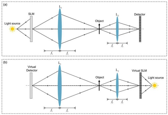
Figure 1.
The imaging configuration of dual photography in the mode of structured illumination: (a) the primal configuration; (b) the dual configuration.
When the SLM is placed at the image plane to modulate the image of the object in ambient light illumination, this mode of operation is commonly referred to structured detection. We can extend the principle of dual photography from the mode of structured illumination to the mode of structured detection. Figure 2 shows the imaging configuration of dual photography in the mode of structured detection. Figure 2a shows the primal configuration, where the object is imaged by an imaging lens L1 onto the SLM, and then imaged by imaging lens L2 onto the detector. Figure 2b shows the dual configuration, where the object is imaged by imaging lenses L1 and L2 onto the virtual SLM, and then is imaged by imaging lens L2 onto the virtual detector. It should be note that Figure 2a,b are formally asymmetric, because in practice modulation should be carried out before detection, hence the delay lens L2 is added in Figure 2b.
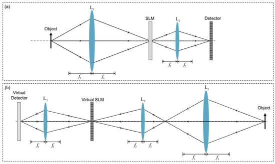
Figure 2.
The imaging configuration of dual photography in the mode of structured detection: (a) the primal configuration; (b) the dual configuration.
Considering that light-field imaging needs to obtain 2D angular information of the light rays and the camera usually works for objects in ambient light illumination or self-luminous objects, we extend the dual photography of structured detection mode from real space to Fourier space, which is called Fourier dual photography. Figure 3a shows the primal imaging configuration of Fourier dual photography, where the object is imaged by the imaging lens onto the SLM, and then focused by the Fourier lens onto the 2D detector at the Fourier plane. Figure 3b shows the dual configuration of Fourier dual photography, where the object is imaged by the imaging lens onto the image plane and then focused by the Fourier lens onto the virtual SLM, and finally imaged onto the virtual detector by the Fourier lens.
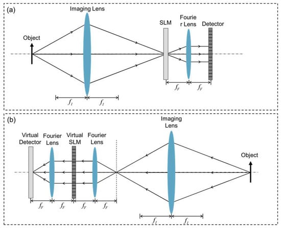
Figure 3.
The imaging configuration of Fourier dual photography: (a) the primal configuration; (b) the dual configuration.
3. Methods
The FRLFC adopts the imaging configuration of Fourier dual photography shown in Figure 3a. According to the principle of dual photography, the SLM acts as a virtual detector that can computationally reconstruct a dual image of the object to record the 2D spatial information with full resolution of the SLM. By loading multiple structured patterns onto the SLM to modulate the image of the object, multiple Fourier spectrum images can be captured by the detector. The Fourier spectrum signals recorded by each pixel of the detector can be used to reconstruct a perspective image of the object using the single-pixel imaging method [31]. The images reconstructed by different pixels of the detector contain the 2D angular information of light rays because the Fourier spectrums recorded by different pixels correspond to the light rays with different angles.
Figure 4 shows how the depth information of objects in a scene is recorded by the FRLFC. A, B, and C represent three different pixels of the detector, pixel B is on the optical axis of the optical system. The spatial coordinate of perspective images reconstructed by the single-pixel detector is determined by the SLM. , and represent the spatial coordinate range of the perspective images reconstructed by pixels A, B, and C, respectively.
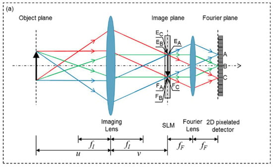
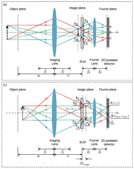
Figure 4.
The principle that depth information of objects is recorded by the FRLFC. (a) The object is at the object plane. (b) The object is in front of the object plane. (c) The object is behind the object plane. A, B, and C represent three different pixels of the 2D detector; and represent object distance and image distance, respectively; and represent the focal length of the imaging lens and the Fourier lens, respectively; , and represent the spatial coordinate range of the images reconstructed by pixels A, B, and C, respectively.
When the object (solid arrow) is at the conjugate object plane of the SLM as shown in Figure 4a, the spatial coordinates of the images reconstructed by pixels A, B, and C are the same, where , and are overlapped. However, if the object (dash arrow) is out of the conjugate object plane as shown in Figure 4b,c, the spatial coordinates of the images reconstructed by pixels A, B, and C are not the same, and , and are not overlapped. Specifically, when the object is in front of the conjugate object plane as shown in Figure 4b, the image reconstructed by pixel A deviates upward from the image reconstructed by pixel B, and the image reconstructed by pixel C deviates downward from the image reconstructed by pixel B. In contrast, when the object is behind the conjugate object plane as shown in Figure 4c, the image reconstructed by pixel A deviates downward from the image reconstructed by pixel B, and the image reconstructed by pixel C deviates upward from the image reconstructed by pixel B. The coordinate deviation value of the reconstructed image is related to the depth of the object and the position of the pixel. Therefore, the depth information of the objects can be obtained by use of the images reconstructed by different pixels of the detector. In Figure 4c, represent the coordinates deviation values of the image reconstructed by pixel A, and is the position deviation value of the image plane from the SLM plane.
Based on the perspective images reconstructed by different pixels, we can digitally refocus on the objects at different depths. The digital refocusing algorithm is summarized as follows:
Step 1: Calculating the coordinate deviation value of the image reconstructed by the single-pixel detector according to the refocusing depth :
where is the coordinate of the single-pixel detector, and is the coordinate of the center point B of the Fourier spectrum image.
Step 2: Shifting the perspective images reconstructed by the pixel in the Fourier domain:
where is the perspective images reconstructed by the pixel; is the shifted perspective images; is the frequency coordinate; and are the Fourier transform and inverse Fourier transform operators, respectively, is the imaginary unit.
Step 3: Summing all shifted images to obtain the refocused image at the depth :
Step 4: Changing the refocusing depth and repeating Steps 1 to 3 to obtain object images at different depths.
Color light-field imaging with the FRLFC can be achieved by placing a color detector at the Fourier plane. The 2D color detector can not only record the angular information but also record the color information. Each pixel of the detector can obtain three groups of 1D intensity sequences, corresponding to red, green, and blue channels. Utilizing the three groups 1D intensity sequences, we can reconstruct red, green, and blue perspective images from every pixel of the detector. Based on all the perspective images, we can realize color light-field imaging by using the steps mentioned above.
4. Results and Discussion
To demonstrate the light-field imaging capability of the FRLFC, we conduct two experiments. The SLM used in the experiments is a liquid-crystal device (LCD, 5.5 inches, 1440 × 2560 pixels, pixel size 47.25 µm, a mobile phone display). The 2D detector used in experiments is a color charge coupled device (CCD) (Point Grey: GS3-U3-60QS6C-C, 1 inch CCD, 2736 × 2190 pixels, pixel size 4.54 µm). The focal lengths of the imaging lens (Nikon: f/1.8D AF NIKKOR) and the Fourier lens are 50 mm and 15 mm, respectively.
In the first experiment, we attempted to reconstruct a 3D scene consisting of three toy masks with different depths in ambient light illumination. To ensure the scene was uniformly illuminated, we used eleven white light-emitting diodes (LED) (color temperature 6500 k, brightness 1000 lumens) to illuminate the scene from different directions. We loaded a series of Hadamard basis patterns on the LCD to modulate the image of the 3D objects according to the Hadamard single-pixel imaging method [30]. The Hadamard patterns were displayed in a 128 × 128 pixel area of the LCD, that is, the size of the Hadamard patterns were 128 × 128 pixels. Figure 5a shows some examples of the Hadamard basis patterns. We captured 128 × 128 Fourier spectrum images, each of which corresponds to a Hadamard basis pattern displaced on the LCD. Figure 5b shows a Fourier spectrum image captured by the camera. As the pixel size of the CCD is only 4.54 µm, the light signal detected by each pixel is very weak. In order to improve the signal-to-noise ratio, we bound multiple pixels of the CCD into a single-pixel detector, obviously at the expense of spatial resolution. The layout of the single-pixel detectors is shown in Figure 5c, where each orange dot represents a single-pixel detector. The radius of each orange dot is 50 pixels.

Figure 5.
(a) Examples of the Hadamard basis patterns. (b) The Fourier spectrum image recorded by the detector. (c) The layout of the single-pixel detectors.
Using the single-pixel imaging method, we can reconstruct red, green, and blue perspective images of the objects from the measurements of each single-pixel detector. The size of the reconstructed images is 128 × 128 pixels, which is the same as that of the modulation patterns. Figure 6a1–d1 show the positions of single-pixel detectors (orange dots). Figure 6a2–a4,b2–b4,c2–c4,d2–d4 show four groups of perspective images reconstructed by the leftmost, topmost, rightmost, and bottommost single-pixel detectors, respectively. It can be seen that the perspective images reconstructed by different single-pixel detectors are shifted with each other, as shown in Figure 6a2–d2. Figure 6e shows the physical size of the masks. These results confirm that the images reconstructed with different single-pixel detectors contain different angle information. With the perspective images reconstructed by all the single-pixel detectors, we can digitally refocus the objects at different depths by using the algorithm mentioned above. Using the red, green, and blue refocus images, we can synthesize digitally refocused full-color images, as shown in Figure 7.
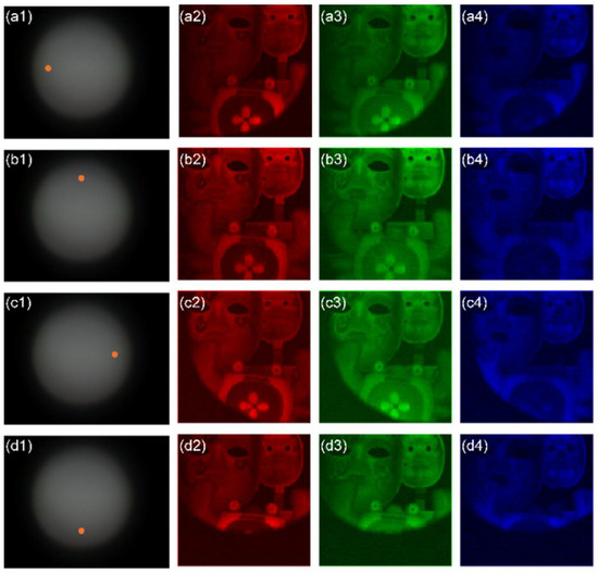
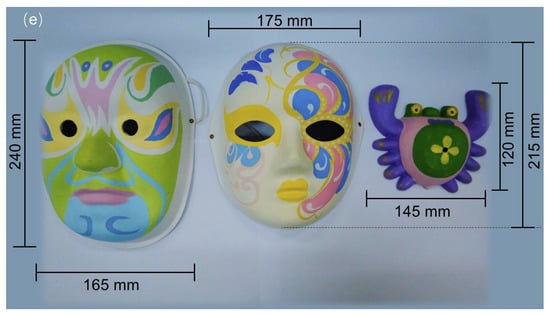
Figure 6.
(a1–d1) The positions of single-pixel detectors (orange dots); (a2–a4) the perspective images reconstructed by the leftmost single-pixel detector; (b2–b4) the perspective images reconstructed by the topmost single-pixel detector; (c2–c4) the perspective images reconstructed by the rightmost single-pixel detector; (d2–d4) the perspective images reconstructed by the bottommost single-pixel detector (see Visualization S1); (e) the physical size of the masks.

Figure 7.
The images digitally refocused at (a) the farthest object, (b) the middle object, and (c) the nearest object indicated by the red arrow respectively (see Visualization S2).
In the second experiment, we attempt to capture a scene of self-luminous objects with the FRLFC. The scene consists of three LED lamps with different colors and shapes. The experimental parameters are the same as those of the first experiment. Figure 8a1–d1 show the positions of single-pixel detectors (orange dots). Figure 8a2–a4,b2–b4,c2–c4,d2–d4 show four groups of perspective images reconstructed by the leftmost, topmost, rightmost, and bottommost single-pixel detectors, respectively. It can be seen that the perspective images reconstructed by different single-pixel detectors are shifted with each other, as shown in Figure 8a2–d2. Figure 8e shows the physical size of the self-luminous objects. Based on the perspective images reconstructed by all single-pixel detectors, we can reconstruct the image of the objects at different depths, as shown in Figure 9.
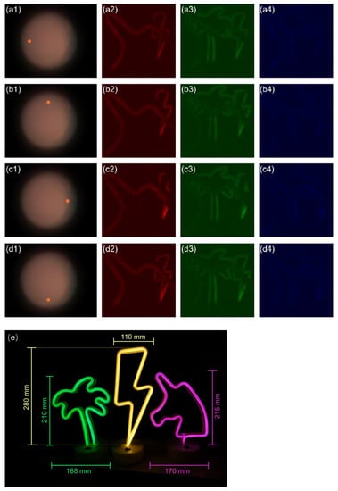
Figure 8.
(a1–d1) The positions of single-pixel detectors (orange dots); (a2–a4) the perspective images reconstructed by the leftmost single-pixel detector; (b2–b4) the perspective images reconstructed by the topmost single-pixel detector; (c2–c4) the perspective images reconstructed by the rightmost single-pixel detector; (d2–d4) the perspective images reconstructed by the bottommost single-pixel detector (see Visualization S3); (e) the physical size of the self-luminous objects.

Figure 9.
The images digitally refocused of the self-luminous objects at (a) the farthest object, (b) the middle object, and (c) the nearest object indicated by the red arrow respectively (see Visualization S4).
For a common camera, the lateral resolution of the acquired image is mainly determined by the imaging resolution of the imaging lens and the sampling frequency of the digital image sensor. For the proposed FRLFC, since the SLM acts as a virtual digital image sensor, the lateral resolution is determined by the imaging resolution of the imaging lens and the sampling frequency of the SLM. In the experiment, the imaging resolution of the imaging lens used is about (), which is much smaller than the pixel size of the LCD spatial light modulator of 47.25 µm. Therefore, the lateral resolution of the FRLFC in the experiment is mainly determined by the pixel size of the LCD.
Depth of field (DOF) is an important performance parameter of light-field camera [32]. We have tested the DOF of the FRLFC. In the experiment, a lamp with twelve LED beads is used as a self-luminous object to be imaged. The size of this lamp is approximately 22 mm × 40 mm. Figure 10 shows the reconstructed images of the lamp at different depths using the single-pixel imaging method with the CCD as a single-pixel detector, which is equivalent to that of a common camera at its maximum aperture according to the principle of dual photography. In the figure, U200, U250 and others represent the object distance u = 200 mm, u = 250 mm, etc. The images are considered clear from u = 600 mm to u = 800 mm, so that the DOF is about 200 mm. Figure 11 shows the reconstruction images of the lamp at different depths using the single-pixel imaging method with the single-pixel detector whose radius is 10 pixels at the center of the Fourier spectrum, which is equivalent to that of a common camera at radius 10 pixels aperture. As can be seen from Figure 11, the images are considered clear from u = 200 mm to u = 1350 mm, so that the DOF is longer than 1150 mm. The smaller the size of the single-pixel detector, the longer the DOF of the reconstructed image. Therefore, when a pixel of the camera is used as a single-pixel detector, an extreme DOF can be obtained for the FRLFC. Importantly, since the spatial resolution of the reconstructed image by the single-pixel detector is determined by the sampling frequency of the SLM rather than the size of the single-pixel detector, the proposed FRLFC can provide an extreme DOF without sacrificing spatial resolution. In comparison, the light-field camera with MLA provides a longer DOF than the common camera at the expense of image resolution. It should be noted that the light-field camera mentioned above does not include the light-field microscope.

Figure 10.
The reconstructed images of the lamp at different depths using the single-pixel imaging method with the CCD as a single-pixel detector.
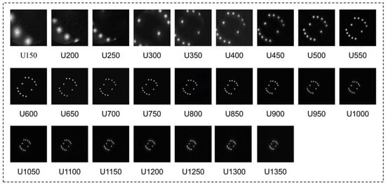
Figure 11.
The reconstruction images of the lamp at different depths using the single-pixel imaging method with the single-pixel detector whose radius is 10 pixels.
5. Conclusions
In summary, we have developed a light-field camera based on dual photography. The principle of dual photography is extended from real space to Fourier space for obtaining 2D angular information of the light rays. Experimental results demonstrate that the proposed light-field camera can realize color light-field imaging. Compared with conventional light-field cameras with MLA, the proposed camera avoids the resolution trade-off problem and the full-resolution light-field imaging can be realized theoretically. High resolution angular information obtained can also result in light-field imaging with an extreme depth of field. Although the proposed method is currently not suitable for dynamic scene imaging, it has a potential of high-resolution light-field imaging for static scenes and provides a new idea for developing the full resolution light-field camera.
Supplementary Materials
The following supporting information can be downloaded at: https://www.mdpi.com/article/10.3390/photonics9080559/s1, Visualization S1: The reconstructed perspective images; Visualization S2: The images digitally refocused; Visualization S3: The reconstructed perspective images of the self-luminous objects; Visualization S4: The images digitally refocused of the self-luminous objects.
Author Contributions
Conceptualization, J.Z. and M.Y.; validation, Y.H., M.Y., Z.H., J.P., Z.Z. and J.Z.; writing, M.Y., Y.H. and J.Z.; supervision, J.Z.; funding acquisition, M.Y., Z.Z., J.P. and J.Z. All authors have read and agreed to the published version of the manuscript.
Funding
This research was funded by National Natural Science Foundation of China (NSFC), grant numbers 61905098 and 61875074; Fundamental Research Funds for the Central Universities, grant number 11618307; Guangdong Basic and Applied Basic Research Foundation, grant numbers 2020A1515110392 and 2019A1515011151; Talents Project of Scientific Research for Guangdong Polytechnic Normal University, grant number 2021SDKYA049.
Institutional Review Board Statement
Not applicable.
Informed Consent Statement
Not applicable.
Data Availability Statement
The data presented in this study are available on reasonable request from the corresponding author.
Conflicts of Interest
The authors declare no conflict of interest.
References
- Levoy, M. Light Fields and Computational Imaging. Computer 2006, 39, 46–55. [Google Scholar] [CrossRef]
- Ihrke, I.; Restrepo, J.; Mignard-Debise, L. Principles of Light Field Imaging: Briefly Revisiting 25 Years of Research. IEEE Signal Process. Mag. 2016, 33, 59–69. [Google Scholar] [CrossRef]
- Javidi, B.; Carnicer, A.; Arai, J.; Fujii, T.; Hua, H.; Liao, H.; Martínez-Corral, M.; Pla, F.; Stern, A.; Waller, L.; et al. Roadmap on 3D integral imaging: Sensing, processing, and display. Opt. Express 2020, 28, 32266–32293. [Google Scholar] [CrossRef]
- Arimoto, H.; Javidi, B. Integral three-dimensional imaging with digital reconstruction. Opt. Lett. 2001, 26, 157–159. [Google Scholar] [CrossRef]
- Okano, F.; Hoshino, H.; Arai, J.; Yuyama, I. Real-time pickup method for a three-dimensional image based on integral photography. Appl. Opt. 1997, 36, 1598–1603. [Google Scholar] [CrossRef] [PubMed]
- Adelson, E.H.; Wang, J.Y.A. Single lens stereo with a plenoptic camera. IEEE Trans. Pattern Anal. Mach. Intell. 1992, 14, 99–106. [Google Scholar] [CrossRef]
- Ng, R.; Levoy, M.; Brédif, M.; Duval, G.; Horowitz, M.; Hanrahan, P. Light Field Photography with a Hand-Held Plenoptic Camera. Ph.D. Dissertation, Stanford University, Stanford, CA, USA, 2005. [Google Scholar]
- Georgiev, T.; Zheng, K.C.; Curless, B.; Salesin, D.; Nayar, S.; Intwala, C. Spatio-angular resolution tradeoffs in integral photography. Render. Tech. 2006, 2006, 21. [Google Scholar]
- Llavador, A.; Sola-Pikabea, J.; Saavedra, G.; Javidi, B.; Martínez-Corral, M. Resolution improvements in integral microscopy with Fourier plane recording. Opt. Express 2016, 24, 20792–20798. [Google Scholar] [CrossRef]
- Guo, C.; Liu, W.; Hua, X.; Li, H.; Jia, S. Fourier light-field microscopy. Opt. Express 2019, 27, 25573–25594. [Google Scholar] [CrossRef]
- Hua, X.; Liu, W.; Jia, S. High-resolution Fourier light-field microscopy for volumetric multi-color live-cell imaging. Optica 2021, 8, 614–620. [Google Scholar] [CrossRef]
- Stefanoiu, A.; Scrofani, G.; Saavedra, G.; Martínez-Corral, M.; Lasser, T. What about computational super-resolution in fluorescence Fourier light field microscopy? Opt. Express 2020, 28, 16554–16568. [Google Scholar] [CrossRef] [PubMed]
- Linda Liu, F.; Kuo, G.; Antipa, N.; Yanny, K.; Waller, L. Fourier diffuserScope: Single-shot 3D Fourier light field microscopy with a diffuser. Opt. Express 2020, 28, 28969–28986. [Google Scholar] [CrossRef] [PubMed]
- Levoy, M.; Hanrahan, P. Light Field Rendering. In Proceedings of the 23rd Annual Conference on Computer Graphics and Interactive Techniques, New Orleans, LA, USA, 4–9 August 1996. [Google Scholar]
- Masselus, V.; Peers, P.; Dutré, P.; Willems, Y.D. Relighting with 4d incident light fields. ACM Trans. Graph. 2003, 22, 613–620. [Google Scholar] [CrossRef]
- Veeraraghavan, A.; Raskar, R.; Agrawal, A.; Mohan, A.; Tumblin, J. Dappled photography: Mask enhanced cameras for heterodyned light fields and coded aperture refocusing. ACM Trans. Graph. 2007, 26, 69. [Google Scholar] [CrossRef]
- Liang, C.K.; Lin, T.H.; Wong, B.Y.; Liu, C.; Chen, H.H. Programmable Aperture Photography: Multiplexed Light Field Acquisition. In ACM SIGGRAPH 2008 Papers; Association for Computing Machinery: New York, NY, USA, 2008; pp. 1–10. [Google Scholar]
- Nguyen, H.N.; Miandji, E.; Guillemot, C. Multi-mask camera model for compressed acquisition of light fields. IEEE Trans. Comput. Imaging 2021, 7, 191–208. [Google Scholar] [CrossRef]
- Edgar, M.P.; Gibson, G.M.; Padgett, M.J. Principles and prospects for single-pixel imaging. Nat. Photonics 2019, 13, 13–20. [Google Scholar] [CrossRef]
- Zhang, Z.; Ma, X.; Zhong, J. Single-pixel imaging by means of Fourier spectrum acquisition. Nat. Commun. 2015, 6, 6225. [Google Scholar] [CrossRef]
- Duarte, M.F.; Davenport, M.A.; Takhar, D.; Laska, J.N.; Sun, T.; Kelly, K.F.; Baraniuk, R.G. Single-pixel imaging via compressive sampling. IEEE Signal Process. Mag. 2008, 25, 83–91. [Google Scholar] [CrossRef]
- Sun, B.; Edgar, M.P.; Bowman, R.; Vittert, L.E.; Welsh, S.; Bowman, A.; Padgett, M.J. 3D Computational imaging with single-pixel detectors. Science 2013, 340, 844–847. [Google Scholar] [CrossRef]
- Sun, M.-J.; Edgar, M.P.; Phillips, D.B.; Gibson, G.M.; Padgett, M.J. Improving the signal-to-noise ratio of single-pixel imaging using digital microscanning. Opt. Express 2016, 24, 10476–10485. [Google Scholar] [CrossRef]
- Peng, J.; Yao, M.; Cheng, J.; Zhang, Z.; Li, S.; Zheng, G.; Zhong, J. Micro-tomography via single-pixel imaging. Opt. Express 2018, 26, 31094–31105. [Google Scholar] [CrossRef] [PubMed]
- Yao, M.; Cheng, J.; Huang, Z.; Zhang, Z.; Li, S.; Peng, J.; Zhong, J. Reflection light-field microscope with a digitally tunable aperture by single-pixel imaging. Opt. Express 2019, 27, 33040–33050. [Google Scholar] [CrossRef]
- Yao, M.; Cai, Z.; Qiu, X.; Li, S.; Peng, J.; Zhong, J. Full-color light-field microscopy via single-pixel imaging. Opt. Express 2020, 28, 6521–6536. [Google Scholar] [CrossRef]
- Gregory, T.; Edgar, M.P.; Gibson, G.M.; Moreau, P.-A. A Gigapixel Computational Light-Field Camera. arXiv 2019, arXiv:1910.08338. [Google Scholar]
- Usami, R.; Nobukawa, T.; Miura, M.; Ishii, N.; Watanabe, E.; Muroi, T. Dense parallax image acquisition method using single-pixel imaging for integral photography. Opt. Lett. 2020, 45, 25–28. [Google Scholar] [CrossRef]
- Sen, P.; Chen, B.; Garg, G.; Marschner, S.R.; Horowitz, M.; Levoy, M.; Lensch, H.P.A. Dual Photography. In ACM SIGGRAPH 2005 Papers; Association for Computing Machinery: New York, NY, USA, 2005; pp. 745–755. [Google Scholar]
- Max, B.; Emil, W. Principles of Optics: Electromagnetic Theory of Propagation, Interference and Diffraction of Light, 6th ed.; Elsevier: Great Britain, UK, 2013. [Google Scholar]
- Zhang, Z.; Wang, X.; Zheng, G.; Zhong, J. Hadamard single-pixel imaging versus Fourier single-pixel imaging. Opt. Express 2017, 25, 19619–19639. [Google Scholar] [CrossRef] [PubMed]
- Kim, H.M.; Kim, M.S.; Chang, S.; Jeong, J.; Jeon, H.-G.; Song, Y.M. Vari-focal light field camera for extended depth of field. Micromachines 2021, 12, 1453. [Google Scholar] [CrossRef] [PubMed]
Publisher’s Note: MDPI stays neutral with regard to jurisdictional claims in published maps and institutional affiliations. |
© 2022 by the authors. Licensee MDPI, Basel, Switzerland. This article is an open access article distributed under the terms and conditions of the Creative Commons Attribution (CC BY) license (https://creativecommons.org/licenses/by/4.0/).