Article

Desensitization Design Method for Freeform TMA Optical Systems Based on Initial Structure Screening

1
Changchun Institute of Optics, Fine Mechanics and Physics, Chinese Academy of Sciences, Changchun 130033, China
2
University of the Chinese Academy of Sciences, Beijing 100049, China
*
Author to whom correspondence should be addressed.
Photonics 2022, 9(8), 544; https://doi.org/10.3390/photonics9080544
Submission received: 12 July 2022 / Revised: 28 July 2022 / Accepted: 29 July 2022 / Published: 3 August 2022
(This article belongs to the Special Issue Freeform Optics)

Abstract

:
Achieving aberration correction can improve the imaging quality of an optical system, and reducing the error sensitivity of system can improve the realizability of the system. In order to obtain an off-axis three-mirror optical system with high image quality and low error sensitivity, a design method is proposed which obtains the initial structure of the three-mirror anastigmatic (TMA) optical system with low error sensitivity through a nondominated sorting genetic algorithm II (NSGA-II). Combining the comprehensive evaluation function of image quality and error sensitivity, this method iteratively selects multiple freeform surface types to determine the combination with the lowest error sensitivity and obtains the freeform TMA optical system with optimal overall performance. A freeform TMA optical system is designed by the method proposed in this paper, and the error sensitivity of the optical system is analyzed. The results show that the image quality of the freeform optical system is effectively improved and the error sensitivity is effectively reduced with the same error applied, which verifies the correctness and practicality of the method.

1. Introduction

TMA optical systems can achieve a larger relative aperture, larger field of view (FOV), and higher imaging quality when combined with freeform optical surfaces with strong aberration correction capability [1,2,3,4,5]. High-performance optical systems are up-and-coming and have been implemented [6,7,8]. However, due to the non-rotational symmetry of the system, the complexity and difficulty of the processing and alignment of freeform TMA optical systems are more significant, and the sensitivity of optical element position errors is also higher [9,10,11]. Therefore, it is of great significance for the high-performance imaging design and realization of the freeform TMA optical system if the error sensitivity can be reduced while achieving the high-performance optical system.
We believe that two aspects of the desensitization design of freeform optical systems are essential: the first is to obtain the initial structure of the optical system with low error sensitivity, and the second is the desensitization optimization of the freeform optical system. The close combination of the two aspects is an effective way to obtain a freeform TMA optical system with low error sensitivity.
Obtaining the initial structure is the beginning of optical design. An excellent initial structure plays a critical role in the optical system’s subsequent optimization and final performance realization. The traditional initial structure solution for optical systems mainly focuses on the object-image relationship and aberration correction. In recent years, some new initial structure solution methods have been reported for freeform systems, such as the Wassermann-Wolf differential-equations method [12,13,14], the simultaneous multi-surface design method [15,16], and the design method based on point-by-point construction and iteration [17,18,19,20], etc., However, not many publicly reported initial structure solution methods have taken the performance of optical system error sensitivity as the core of the investigation. Some optical system initially structure solutions on error sensitivity, primarily applying damped least squares (DLS) to obtain local minima rather than optimal global solutions [21,22,23]. Some other solution methods are mainly qualitative and lack quantitative evaluation indicators.
For the desensitization optimization of optical systems, the usual methods are the global optimization method, parameter control method, and freeform surface optimization method. The global optimization method is to optimize and iterate on a large sample of optical systems that have completed image quality optimization and to select systems with better tolerance robustness [24,25,26], which is a qualitative method. The parameter control method is based on the optical system parameters obtained from theoretical studies with a clear regular or quantitative relationship with the error sensitivity. In optimization, process desensitization is achieved by direct or indirect control of these parameters [10,27,28,29,30]. This method is a quantitative desensitization design method that can visually regulate specific values associated with the error sensitivity of the optical system. In recent years, some other studies have shown that optical systems applied to certain freeform surfaces have lower error sensitivity than those applied aspheric surfaces [31,32,33], which leaves the application of freeform surfaces to improve the imaging performance of optical systems and the potential of error sensitivity to be exploited.
In light of the above discussion, this paper proposes a desensitization design method for freeform TMA optical systems based on initial structure screening. The method combines the features of the global optimization method, parameter control method, and freeform optimization method and considers the advantages of multiple design methods. First, the initial structure of the TMA optical system is selected by the NSGA-II, and the freeform surface is introduced into the conic TMA system in order to improve the system performance. The characteristic parameters affecting the error sensitivity of the freeform optical system are controlled based on the proposed quantitative evaluation function of the error sensitivity. In order to exploit the desensitization potential of the freeform surface, the combination of multiple types of freeform surfaces is screened and optimized to obtain the best combination of surface types considering the optical system’s imaging quality and error sensitivity. Finally, the desensitization design of the free-form optical system is produced. In order to verify the effectiveness of the desensitization design method, a freeform TMA optical system with a focal length of 100 mm, an F-number of 5, and a FOV of 3° × 3° is used as an example for the desensitization design. The error sensitivity analysis with the counterpart conic optical system shows that the freeform optical system obtained by applying the desensitization design method has a significant improvement in the image quality and error sensitivity performance with the same error applied.

2. Error Sensitivity Evaluation Function for Freeform Surfaces
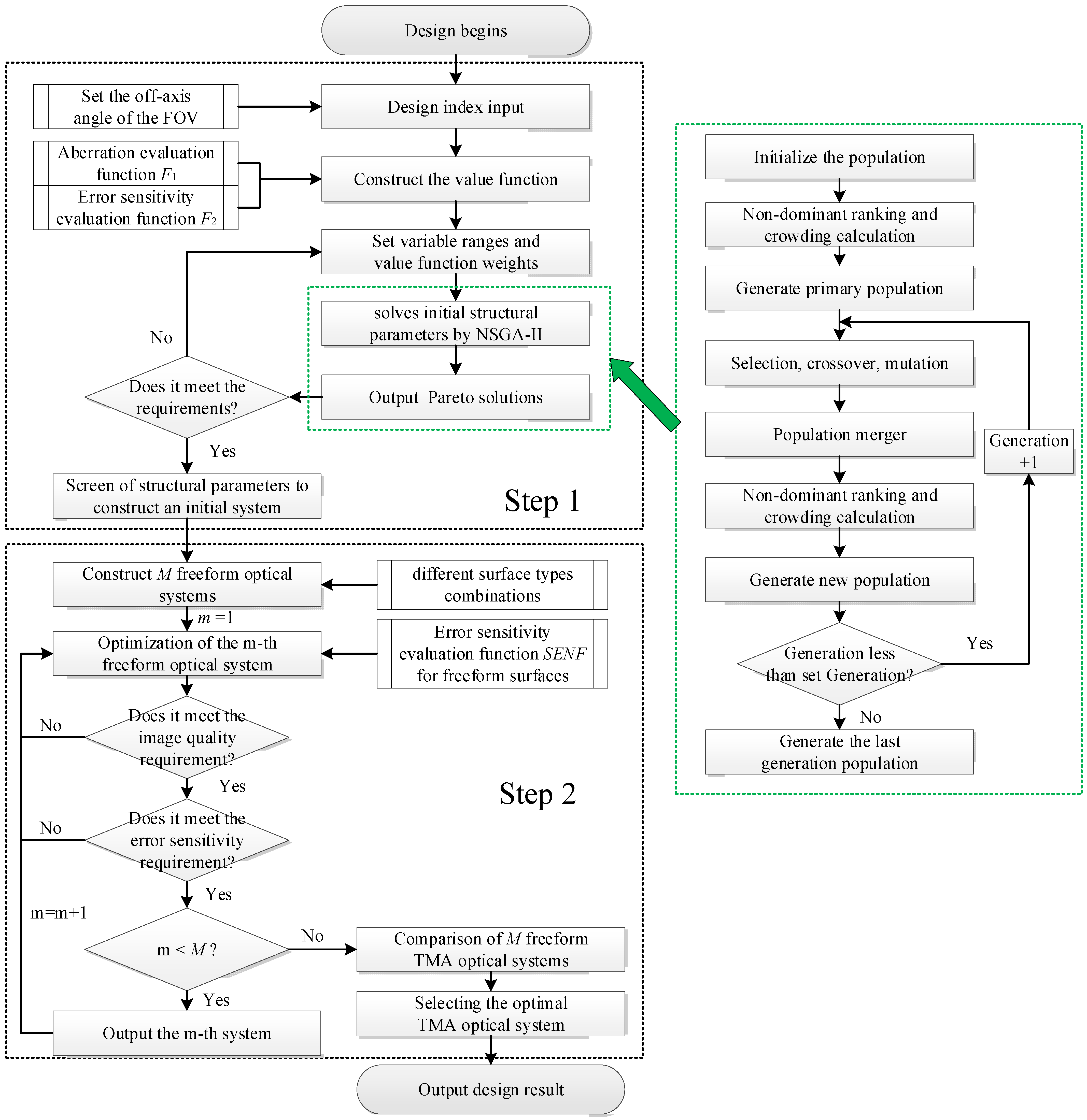
Tilt is an important manifestation of the position error of optical elements [34]. It mainly causes asymmetric aberrations such as astigmatism, which is difficult to compensate for the image quality by defocus. Therefore, the tilt error has been taken as an essential research object in the theoretical research of the error sensitivity of optical systems.
A tilt sensitivity evaluation function was proposed in our previous study and effectively used to evaluate the error sensitivity of the conic TMA optical system. The method is improved to evaluate and optimize the error sensitivity of the freeform TMA optical system by combining the method with ray sampling.
The error sensitivity evaluation function is the core of the optical system desensitization design. In order to establish an effective evaluation function, the first is to investigate the clear mathematical relationship between the internal parameters of the optical system and the error sensitivity under the condition of tilt error perturbation, and then to control these parameters to achieve the desensitization in the subsequent desensitization design. Based on the geometric ray-tracing method, the error sensitivity of the optical system is manifested by the variation of optical path difference (OPD). By deriving the variation of OPD (ΔOPD) of any ray of the optical system before and after being disturbed by tilt, it is concluded that the larger the slope of the tangent line at the intersection of the ray and the mirror is, the smaller the ΔOPD due to the error is, which means the error sensitivity is lower [30]. Therefore, the tangent slope at the intersection of ray and mirror is determined to be a pivotal factor in characterizing the error sensitivity of the optical system, and a tilt error sensitivity evaluation function with the tangent slope as the core is proposed accordingly.
The schematic diagram of ray propagation at the intersection of the optical element is shown in Figure 1. The intersection of the incidence ray and the mirror is N. The tangent line to the mirror is made at point N. The slope of the tangent line is defined as K.
The tangent slope K at the intersection of ray and mirror is inversely proportional to the tilt error sensitivity of the optical system, so the larger the value of K in the desensitization design is, the lower error sensitivity is. However, the maximum value of K cannot be obtained as a tangent function, leading to the inability to set a suitable threshold. Based on the analysis of the optimization function, the optimization process is usually to obtain the minimum value of the optimization function. Therefore, in order to facilitate the setting of the error sensitivity threshold, the absolute value of the reciprocal of K is defined as τ, and the error sensitivity evaluation function is constructed [34].
Define the mirror tilt error sensitivity evaluation function as SENSurface:
S E N S u r f a c e = k = 1 N O F τ k 2 k ,
where k is the serial number of the field and NOF is the number of FOV sampling points.
Define the optical system tilt error sensitivity evaluation function as SENSystem:
S E N S y s t e m = i = 1 3 S E N S u r f a c e k ,
where i is the serial number of the surface.
Since freeform surfaces do not have rotational symmetry, it is difficult to effectively control the error sensitivity of an optical system by analyzing only one ray. Therefore, it is necessary to extend the application of the error sensitivity evaluation function for freeform optical systems and an error sensitivity evaluation method applicable to any freeform surface is proposed.
In the error sensitivity evaluation method based on ray tracing, aiming at the footprint of a mirror through a certain FOV, the “Ring-Arm” sampling method with high sampling density reflects the idea of global desensitization from the parts to the whole, and achieves the purpose of reducing the comprehensive error sensitivity of the TMA optical system.
The sampling method of “Ring-Arm” is used, and NOR × NOA sampling points are selected. The number of selected Rings is NOR, and the number of selected Arms is NOA. The Rings and Arms are chosen as follows—Ring is defined as follows: Ring # represents the serial number of the Ring, from the center outward as light purple Ring 1, green Ring 2, blue Ring 3, black Ring... representing the possible Rings, dark red Ring NOR. The Arms are defined as follows: Arm # represents the serial number of the Arm, starting from the meridian +90° direction as Arm 1, and sorted counterclockwise as Arm 2, Arm 3, Arm... representing the possible Arms, Arm NOA. For example, Ring 3, Arm2 corresponds to the location of the reference point as shown by the red arrow in Figure 2.
At each sampling point, the tangent slope of the intersection of the ray and the mirror is defined as Ku,v. The error sensitivity of one freeform mirror corresponding to a single FOV is calculated first, and then the average of the error sensitivity of freeform TMA optical system corresponding to each FOV is calculated as the comprehensive error sensitivity evaluation function.
Error sensitivity for a single FOV, a single freeform mirror is defined as SENF:
S E N F = u = 1 N O R v = 1 N O A τ u , v 2 N O R × N O A ,
where, u is the serial number of the Ring, v is the serial number of the Arm.
Error sensitivity for all FOVs corresponding to the freeform TMA optical system is defined as SENFSystem:
S E N F S y s t e m = k = 1 N O F i = 1 3 S E N F i 2 3 N O F ,

3. Design Method

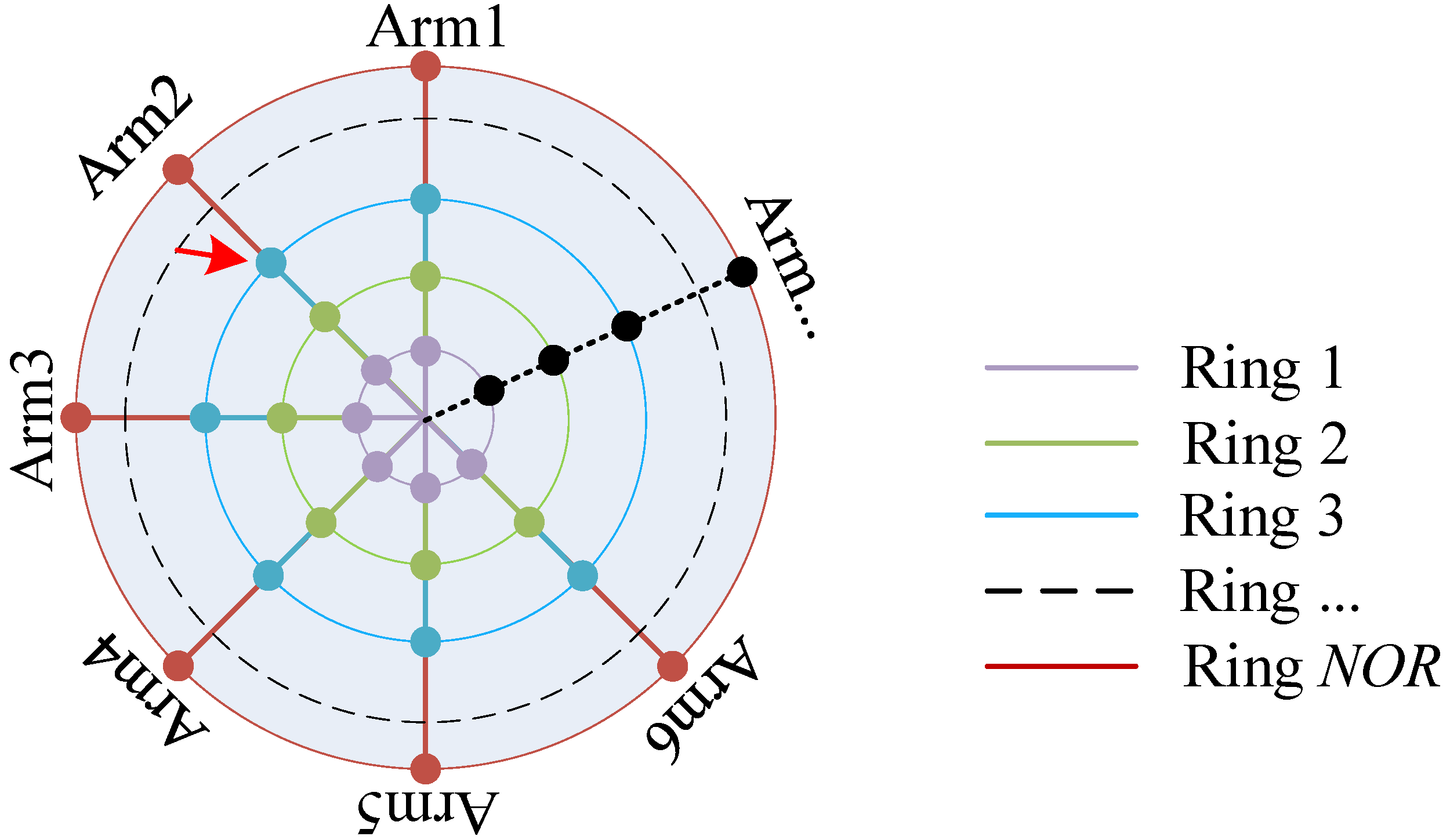
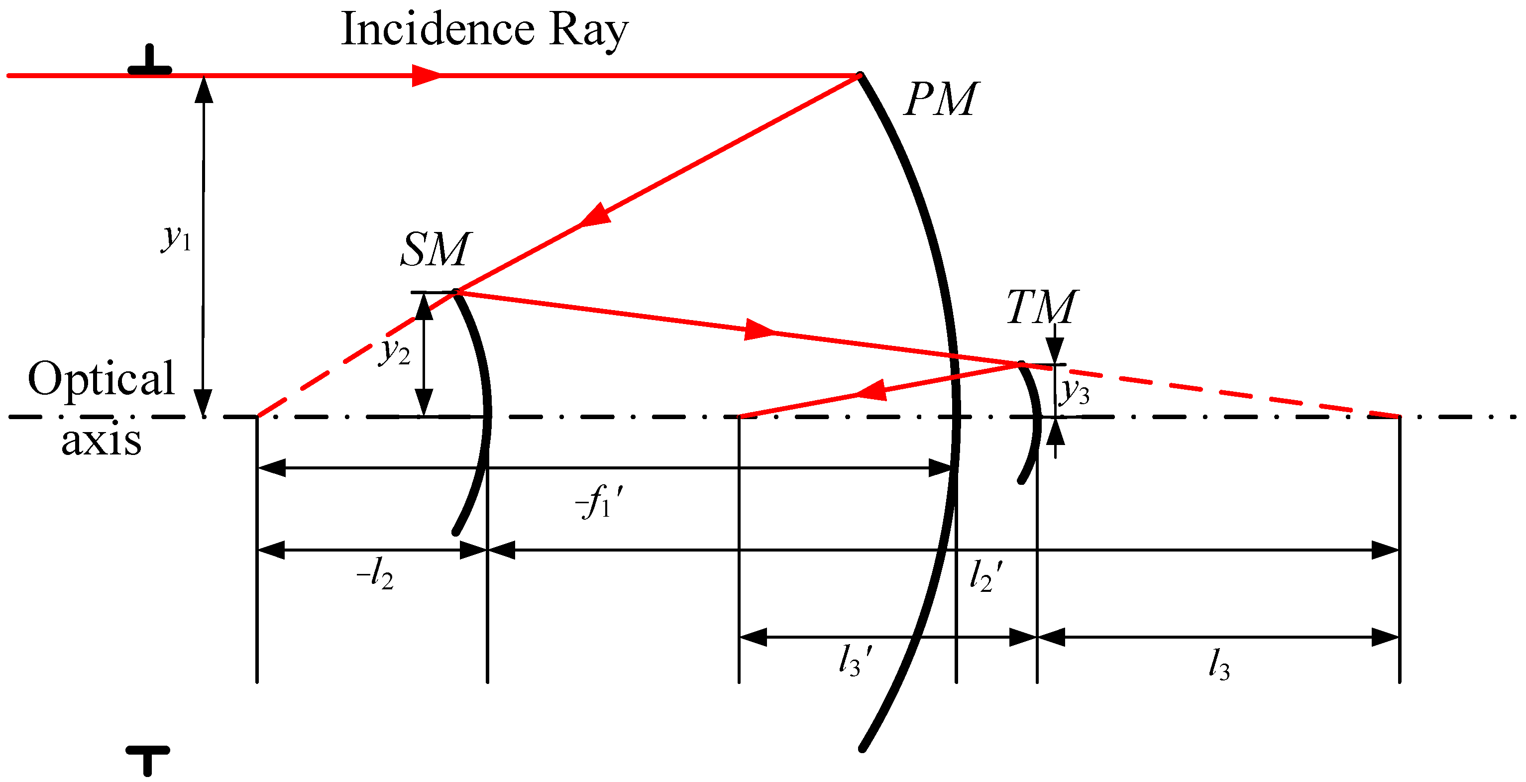
3.1. Initial Structure Construction

In this paper, the NSGA-II algorithm is used to automatically calculate the initial system structure parameters. The NSGA-II algorithm, proposed by Srinivas and Deb in 2000, is one of the most popular multi-objective genetic algorithms, which reduces the complexity of non-inferiority ranking genetic algorithms and has the advantages of fast operation and good convergence of the solution set, making it a benchmark for the performance of other multi-objective optimization algorithms [35]. Minimizing two or more value functions by using the NSGA-II algorithm will result in a compromised set of solutions (Pareto solutions) rather than just the single solution obtained in single-objective optimization algorithms. The researcher can decide the importance of two or more value functions through the analysis and thus select the desired result among the Pareto solutions. The specific process of the NSGA-II algorithm is not described in detail here. In the design of the TMA optical system, the layout of the three-mirror system is shown in Figure 3.
The system consists of three mirrors: primary mirror (PM), secondary mirror (SM), and triple mirror (TM). y1, y2, and y3 are the half-apertures of PM, SM, and TM; the objective distance of the PM is infinity; l2 and l3 are the objective distances of the SM and TM, respectively; f1’, l2’, and l3’ are the image distances of the PM, SM, and TM, respectively. The blocking ratios of SM to PM and TM to SM are α1 and α2, respectively the magnifications of SM and TM are β1 and β2, respectively, and the conic coefficients of each mirror are e12, e22, and e32, respectively. Where
{ α 1 = l 2 f 1 y 2 y 1 α 2 = l 3 l 2 y 3 y 2 , { β 1 = l 2 l 2 β 2 = l 3 l 3 ,
Firstly, two blocking ratios (α1, α2), two magnifications (β1, β2), and three conic coefficients (e12, e22, e32) are set as variables. The initial structure of TMA optical system can be obtained by introducing the parameters into Equation (6).
Assuming that the focal length of the three mirror system is f’, the expressions of the curvature radii of PM, SM, and TM and their corresponding thicknesses are calculated according to the paraxial optical theory as follows:
{ R 1 = 2 f ¢ β 1 β 2 R 2 = 2 α 1 f ¢ β 2 ( 1 + β 1 ) R 3 = 2 α 1 α 2 f ¢ 1 + β 2 ,   { d 1 = ( 1 α 1 ) f ¢ β 1 β 2 d 2 = α 1 ( 1 α 2 ) f ¢ β 2 d 3 = α 1 α 2 f ¢ ,
where R1, R2, and R3 are the radii of curvature of PM, SM, TM respectively, d1, d2, and d3 are the distances between PM and SM, between SM and TM, and between TM and image plane, respectively.
Then, two value functions of NSGA-II algorithm are constructed, which are image quality evaluation function F1 and error sensitivity evaluation function F2. The smaller value of F1 represents the better image quality of the initial structure corresponding to this set of parameters, and the smaller value of F2 represents the lower error sensitivity of it corresponding to this set of parameters. The NSGA-II algorithm is used to minimize the two value functions to generate a set of Pareto solutions, where each set of solutions corresponds to one initial structure parameter.
Setting NSGA-II algorithm value function:
(1)
Aberration evaluation function F1
The relationships between the third-order aberration coefficient and the blocking ratio, magnification, and conic coefficient are as follows:
S I = 1 4 [ ( e 1 2 1 ) β 1 3 β 2 3 e 2 2 α 1 β 2 3 ( 1 + β 1 ) 3 + e 3 2 α 1 α 2 ( 1 + β 2 ) 3 + α 1 β 2 3 ( 1 + β 1 ) ( 1 β 1 ) 2 α 1 α 2 ( 1 + β 2 ) ( 1 β 2 ) 2 ] S I I = e 2 2 ( α 1 1 ) β 2 3 ( 1 + β 1 ) 3 4 β 1 β 2 [ α 2 ( α 1 1 ) + β 1 ( 1 α 2 ) ] ( 1 + β 2 ) ( 1 β 2 ) 2 4 β 1 β 2 + e 3 2 [ α 2 ( α 1 1 ) + β 1 ( 1 α 2 ) ] ( 1 + β 2 ) 3 4 β 1 β 2 + ( α 1 1 ) β 2 3 ( 1 + β 1 ) ( 1 β 1 ) 2 4 β 1 β 2 1 2 S I I I = e 2 2 β 2 ( α 1 1 ) 2 ( 1 β 1 3 ) 4 α 1 β 1 2 [ α 2 ( α 1 1 ) + ( 1 α 2 ) β 1 ] 2 ( 1 + β 2 ) ( 1 β 2 ) 2 4 α 1 α 2 β 1 2 β 2 2 [ α 2 ( α 1 1 ) + β 1 ( 1 α 2 ) ] ( 1 β 2 ) ( 1 + β 2 ) α 1 α 2 β 1 β 2 + β 2 ( 1 + β 1 ) α 1 1 + β 2 a 1 α 2 β 1 β 2 + e 3 2 [ α 2 ( α 1 1 ) + β 1 ( 1 α 2 ) ] 2 ( 1 + β 2 ) 3 4 α 1 α 2 β 1 2 β 2 2 + β 2 ( α 1 1 ) 2 ( 1 + β 1 ) ( 1 β 1 ) 2 4 α 1 β 1 2 β 2 ( α 1 1 ) ( 1 β 1 ) ( 1 + β 1 ) α 1 β 1 S I V = β 1 β 2 β 2 ( 1 + β 1 ) α 1 + 1 + β 2 α 1 α 2 S V = 2 ( α 1 1 ) ( β 1 + 1 ) α 1 2 β 1 + 1 4 ( β 1 + 1 ) ( α 1 1 ) 3 ( β 1 1 ) 2 α 1 2 β 1 3 + 3 ( α 1 1 ) 2 ( β 1 1 ) ( β 1 + 1 ) 2 α 1 2 β 1 2 + 2 ( β 2 + 1 ) ( α 2 β 1 α 1 α 2 + α 2 β 1 ) α 1 2 α 2 2 β 1 β 2 + 3 ( β 2 1 ) ( β 2 + 1 ) ( α 2 β 1 α 1 α 2 + α 2 β 1 ) 2 2 α 1 2 α 2 2 β 1 2 β 2 2 e 2 2 ( α 1 1 ) 3 ( β 1 + 1 ) 3 4 α 1 2 β 1 3 + ( α 2 β 1 α 1 α 2 + α 2 β 1 ) 3 4 α 1 2 α 2 2 β 1 3 β 2 3
where SI, SII, SIII, SIV, and SV are the primary aberration coefficients of spherical aberration, coma, astigmatism, field curvature, and distortion, respectively.
The aberration evaluation function F1 consists of primary aberration coefficients and weights, as shown in Equation (8).
F 1 = ω 1 | S I | + ω 2 | S I I | + ω 3 | S I I I | + ω 4 | S I V | + ω 5 | S V | ,
where ω1, ω2, ω3, ω4, and ω5 are the weights corresponding to SI, SII, SIII, SIV, and SV, respectively.
(2)
Error sensitivity evaluation function F2
The aberration evaluation function F2 consists of the error sensitivity of the three mirrors and weights, as shown in Equation (9).
F 2 = v 1 | S E N 1 | + v 2 | S E N 2 | + v 3 | S E N 3 | ,
where SEN1, SEN2, and SEN3 are the error sensitivities of PM, SM, and TM, respectively, and v1, v2, and v3 are the weights corresponding to the error sensitivities of PM, SM, and TM, respectively.

3.2. Desensitization Design Method for Freeform Optical Systems
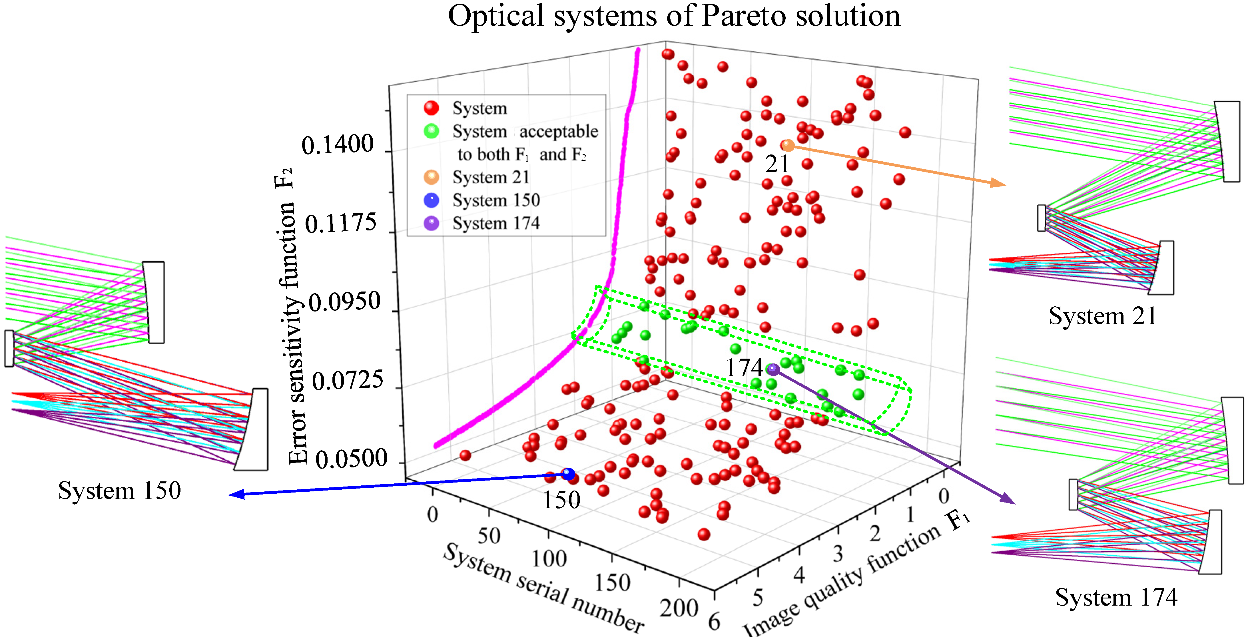
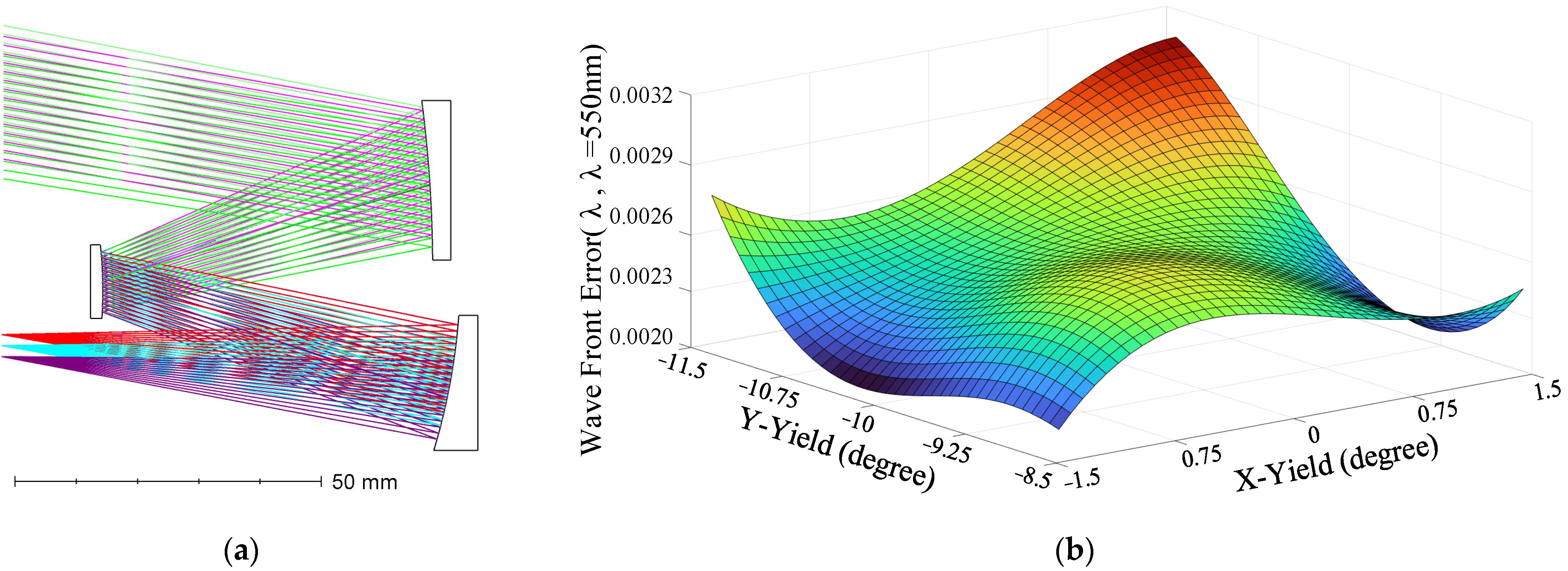
Based on the above analysis, a design method for freeform TMA optical system with low error sensitivity is proposed.
First, the off-axis angle of the FOV is set according to the FOV requirements, and this step has two purposes: one is to meet the requirements of the FOV, and the other is to make the system unobscured. Set the range of the variables according to the structural parameters of the target optical system. The NSGA-II algorithm is used to obtain a set of Pareto solutions, and the conic TMA optical system with acceptable image quality and error sensitivity is selected from the Pareto solution set as the initial structure for the next optimization.
Then, to further optimize the performance of the TMA system (better image quality and lower error sensitivity), freeform surfaces are used in the design and optimization of the TMA system. There are many kinds of freeform surface types; choose a variety of surface types from the freeform surface type library to build M freeform TMA systems (if three freeform surface types are selected, and the mirrors are allowed to use the same surface type, the number of constructed systems is 27; if the mirrors are not allowed to use the same surface, the number of systems constructed is 6) in order to study the performance of the freeform TMA optical system with different freeform surface combinations. After all the M systems are optimized, the optical system with the best image quality and lowest error sensitivity is selected as the optimal system output. Different combinations of freeform surface types are compared and discussed with the design results in Section 5.2. The flow chart of the design method of the freeform TMA optical system with low error sensitivity is shown in Figure 4.

4. Design Example

A COOK TMA optical system with the focal length of 100 mm, F-number of 5, wavelength of 550 nm, square FOV of 3° × 3° (Tangential: −8.5°~−11.5°, Sagittal: −1.5°~1.5°) is designed as an example. The optical system parameters are taken as follows: e12, e22, and e32 are within the range of: −5.0000~5.0000, α1 is within the range of 0.400~0.500, α2 is within the range of 1.500~2.000, β1 is within the range of 1.500~2.000, and β2 is within the range of 0.350~1.000. Setting all items in the image quality evaluation function and error sensitivity evaluation function is of the same importance. The parameters of the NSGA-II algorithm were set as follows: population size set as 200, the number of iterations set as 500, genetic probability set as 0.9, and variation probability set as 0.1.
The NSGA-II algorithm is used to solve, and the Pareto results are shown in Figure 5, where each ball represents a set of solutions. The projection of all systems on the corresponding surface of the F1-F2 plane is the Pareto front (magenta curve). Three representative systems are selected from 200 sets of results for display. System 21 (orange ball) is the system with better image quality and higher error sensitivity among all systems. On the contrary, System 150 (blue ball) is the system with lower error sensitivity and poorer image quality. In Figure 5, the green dashed box is considered to be systems acceptable to both image quality and error sensitivity. System 174 (purple ball) is a system randomly selected in this area. The image quality of system 174 is better than that of system 150, whereas its error sensitivity is lower than that of system 21. Therefore, system 174 is selected as the initial structure of the freeform TMA optical system. The initial structure parameters of System 21, System 150, and System 174 are shown in Table 1.
Next, System 174 was used as the initial structure of the freeform TMA optical system and was optimized. Five Rings and eight Arms (40 reference points) were selected to evaluate and optimize the error sensitivity of the freeform TMA optical system.
In order to compare and select the freeform surface type combination with the best image quality and lowest error sensitivity, we randomly selected three surface types from the freeform surface type library, namely, Fringe Zernike polynomials, XY polynomials and Chebyshev polynomials. The general form of a mathematical expression for a freeform surface involves the addition of freeform terms on the basis of a conic surface, as shown in Equation (10):
z ( x , y ) = c ( x 2 + y 2 ) 1 + 1 ( 1 + k ) c 2 ( x 2 + y 2 ) + j J A j g j ( x , y ) ,
where c is the curvature of the surface, k is the conic coefficient, Aj is the coefficient of the jth freeform term, and gj(x,y) is the freeform surface term described using polynomials such as Fringe Zernike polynomials or XY polynomials.
We use the Fringe Zernike polynomials, Chebyshev polynomials, and XY polynomials with the first to fourth order terms. Therefore, the freeform surface terms of XY polynomials and Chebyshev polynomials can be provided by Equations (11) and (12):
j J A j g j ( x , y ) = m = 0 4 n = 0 4 a m , n x m y n , 1 m + n 4 ,
j J A j g j ( x , y ) = m = 0 4 n = 0 4 a m , n t m , n ( x , y ) , 1 m + n 4 ,
where tm,n(x,y) are subforums of the Chebyshev polynomials. As for the Fringe Zernike polynomials, the freeform surface terms can be provided by Equation (13):
j J A j g j ( x , y ) = j J A j Z j ( ρ , φ ) , j = 2 , 3 , , 13 , 17 , 18 ,
where ρ is the normalized radial ray coordinate and φ is the angular ray coordinate.
The six groups of freeform TMA optical systems were constructed according to the application of different freeform surface types to different mirrors for comparison. The image quality threshold of the freeform TMA optical system was set to 0.0200 λ and the error sensitivity threshold was 0.0700. The surface combination and optimization results of the six freeform TMA optical systems are shown in Table 2.
Through comparative analysis, System 174-F4 has the best image quality and the lowest error sensitivity, and is considered to be the best system. The layout diagram and Root mean square Wavefront Error (RMS WFE) of System 174-F4 are shown in Figure 6.
Subsequently, in order to visualize the magnitude of the performance enhancement of TMA optical system by the introduction of the freeform surface, the error sensitivity of conic TMA optical system (System174) and the freeform TMA optical system (System 174-F4), which is considered to be the best combination of the freeform surface types, were analyzed and compared, respectively, and the error sensitivity comparison is as follows in Figure 7.
Error sensitivity analysis was performed for the freeform optical system (System 174-F4) and the conic optical system (System 174). We used the Monte Carlo tolerance analysis method with 500 samples to calculate the average value of ΔRMS WFE. The tilt angle of each mirror is 0.01° and the error amount obeyed a normal distribution. The results are shown in Figure 8.
The results show that the RMS WFE of conic TMA is 0.0645λ, SENFsystem is 0.0728, and the average ΔRMS WFE is 0.0049λ when disturbed; the RMS WFE of freeform TMA optimized by desensitization design is 0.0026λ, SENFsystem is 0.0266, and the average ΔRMS WFE is 0.0025λ when disturbed. Compared with the conic TMA, the RMS WFE of the freeform TMA is 1/25 of the original, and the average ΔRMS WFE is 51% of the original with the same tilt applied, which can prove that our design method is correct and effective.
To illustrate the effectiveness of the low error sensitivity freeform optical system design method proposed in this paper, we add a set of comparisons. System 174-F0 is optimized by the traditional optimization method, and the goal of optimization is the best image quality. During the optimization process, the three mirrors of System 174-F0 were upgraded to freeform surfaces. In order to better compare with System 174-F4 (the best design result using our proposed method), the three mirrors used the same freeform surface types as System 174-F4. After optimization by traditional methods, the RMS WFE of System 174-F0 is 0.0024 λ. Monte Carlo (same parameter settings as System 174-F4) analysis of System 174-F0 shows an average ΔRMS WFE of 0.0040 when disturbed. With the same tilt applied, the ΔRMS WFE of System 174-F4 (the design result using our proposed method) is 62.5% of that of System 174-F0 (the design result not using our proposed method), which can prove that our design method is effective in the optimization design process of freeform TMA optical system.

5. Discussion

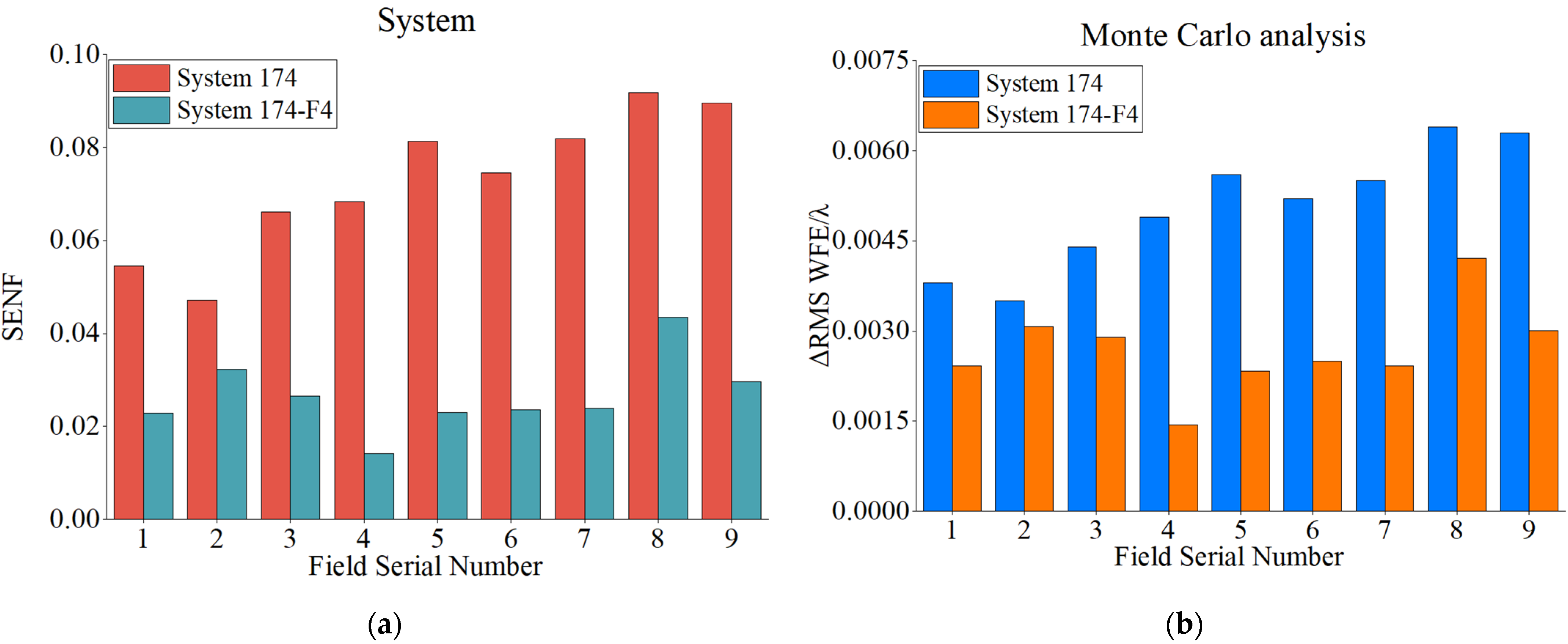
5.1. Discussion of Combined Design Methods

In this paper, a combined design method for freeform TMA optical systems is proposed. The NSGA-II algorithm is applied to obtain an initial conic system acceptable to both image quality and error sensitivity. Compared with the traditional “initial structure + DLS algorithm” method, this method obtains a globally optimal solution instead of an optimal local solution, providing an optimal initial structure for further optimization. A good conic optical system as the initial structure of the freeform optical system can be easily optimized to obtain good design results, thus significantly improving the design efficiency. The performance of the system is then continued to be improved by introducing freeform surfaces. The entire design process combines the advantages of the global optimization method, the parameter control method, and the freeform surface optimization method, in which the global optimization method is more suitable for the search of the initial structure and in the subsequent freeform surface optimization process, and the global optimization method with large sample iterations is not suitable because of the complexity of the freeform surface representation. Therefore, we use the parameter control method to optimize the freeform optical system in the subsequent optimization process. Throughout the design process, we apply different desensitization methods in different steps according to their characteristics, which not only reduces computation time but also obtains good design results. From the design results, the method proposed in this paper is effective.
In addition, when the NSGA-II algorithm is applied to obtain the initial optical system structure parameters, researchers only need to analyze aberration and error sensitivity and set the value function according to the index of the target optical system. The process does not require complex mathematical calculations and program writing, which is simple and easy to implement with good applicability.

5.2. Discussion of Surface Type Combinations and Design Results

As for the design results, as shown in Table 2, the image quality of the freeform TMA optical system is better for the SM with Fringe Zernike polynomials and less error sensitive for the TM with XY polynomials, where the PM adopts Chebyshev polynomials, the SM adopts Fringe Zernike polynomials, and the TM adopts XY polynomials as the optimal freeform surface combination. Since Fringe Zernike polynomials is orthogonal in the circular domain, applying it to the SM (Stop) can obtain the best imaging quality, which is consistent with the conclusion of Y. Zhong and H. Gross‘ comparative analysis [36].
In the design comparison process of this paper, the focus is on comparing the design results of different freeform surface types combinations without considering the difficulty of fabrication. In addition, the number of freeform surface types involved in the comparison is small, and in the further study, the number of freeform surface types will be increased and the manufacturing difficulty of different surface types will be considered for a more comprehensive and integrated analysis.

6. Conclusions

The freeform TMA optical system with low error sensitivity can achieve high imaging quality and be highly resistant to error interruptions. In this paper, the existing error-sensitive evaluation function for conic surfaces is extended to the evaluation of freeform surfaces by combining the “Ring-Arm” reference point sampling method. The NSGA-II algorithm is used to establish the initial structure of a good TMA optical system, and then a comprehensive evaluation function that considering the image quality and error sensitivity of the freeform optical system is used to evaluate and compare various combinations of freeform surface types to determine the optimal freeform surface type. As an example, a freeform TMA optical system with a focal length of 100 mm, an F-number of 5, and a FOV of 3° × 3° is designed and optimized to use Chebyshev polynomials for the PM, Fringe Zernike polynomials for the SM, and XY polynomials for the TM, as the optimal freeform surface combination.
Compared with the conic system (System 174), the image quality of the freeform surface system (System 174-F4) is greatly improved, and the RMS WFE is 1/25 of the original, and the error sensitivity of the three mirrors is greatly reduced with the overall error sensitivity of the system 36.5% of the original. With the same error applied, the ΔRMS WFE is 51% of the original, which verifies the correctness and practicality of the method.

Author Contributions

Conceptualization, Z.Q. and Q.M.; methodology, Z.Q. and Q.M.; software, Z.Q.; validation, Z.Q., Y.Q., C.R. and Q.M.; writing—original draft preparation, Z.Q.; writing—review and editing, Y.Q., C.R. and Q.M.; supervision, X.W. and Q.M.; project administration, X.W. and Q.M. All authors have read and agreed to the published version of the manuscript.

Funding

This research was funded by the Youth Innovation Promotion Association of the Chinese Academy of Sciences (2019219); the National Natural Science Foundation of China (61705220); and the Strategic Priority Research Program of Chinese Academy of Sciences (XDA17010205).

Institutional Review Board Statement

Not applicable.

Informed Consent Statement

Not applicable.

Data Availability Statement

Not applicable.

Conflicts of Interest

The authors declare no conflict of interest. The funders had no role in the design of the study; in the collection, analyses, or interpretation of data; in the writing of the manuscript, or in the decision to publish the results.

References

  1. Liu, X.; Gong, T.; Jin, G.; Zhu, J. Design method for assembly-insensitive freeform reflective optical systems. Opt. Express 2018, 26, 27798–27811. [Google Scholar] [CrossRef] [PubMed]
  2. Meng, Q.; Wang, H.; Wang, K.; Wang, Y.; Ji, Z.; Wang, D. Off-axis three-mirror freeform telescope with a large linear field of view based on an integration mirror. Appl. Opt. 2016, 55, 8962–8970. [Google Scholar] [CrossRef] [PubMed]
  3. Zhang, X.; Zheng, L.; He, X.; Wang, L.; Zhang, F.; Yu, S.; Shi, G.; Zhang, B.; Liu, Q.; Wang, T. Design and fabrication of imaging optical systems with freeform surfaces. In Proceedings of the Current Developments in Lens Design and Optical Engineering XIII, San Diego, CA, USA, 11 October 2012; p. 848607. [Google Scholar]
  4. Fuerschbach, K.; Rolland, J.P.; Thompson, K.P. A new family of optical systems employing φ-polynomial surfaces. Opt. Express 2011, 19, 21919–21928. [Google Scholar] [CrossRef]
  5. Reimers, J.; Bauer, A.; Thompson, K.P.; Rolland, J.P. Freeform spectrometer enabling increased compactness. Light Sci. Appl. 2017, 6, e17026. [Google Scholar] [CrossRef] [PubMed]
  6. Yang, T.; Zhu, J.; Jin, G. Design of free-form imaging systems with linear field-of-view using a construction and iteration process. Opt. Express 2014, 22, 3362–3374. [Google Scholar] [CrossRef] [PubMed]
  7. Zhu, J.; Hou, W.; Zhang, X.; Jin, G. Design of a low F-number free form off-axis three-mirror system with rectangular field-of-view. J. Opt. 2015, 17, 015605. [Google Scholar]
  8. Meng, Q.; Wang, H.; Liang, W.; Yan, Z.; Wang, B. Design of off-axis three-mirror systems with ultrawide field of view based on an expansion process of surface freeform and field of view. Appl. Opt. 2019, 58, 609–615. [Google Scholar] [CrossRef] [PubMed]
  9. Thompson, K. Description of the third-order optical aberrations of near-circular pupil optical systems without symmetry. J. Opt. Soc. Am. A 2005, 22, 1389–1401. [Google Scholar] [CrossRef] [PubMed]
  10. Meng, Q.; Wang, H.; Wang, W.; Yan, Z. Desensitization design method of unobscured three-mirror anastigmatic optical systems with an adjustment-optimization-evaluation process. Appl. Opt. 2018, 57, 1472–1481. [Google Scholar] [CrossRef]
  11. Grey, D. Tolerance sensitivity and optimization. Appl. Opt. 1970, 9, 523–526. [Google Scholar] [CrossRef]
  12. Wassermann, G.D.; Wolf, E. On the Theory of Aplanatic Aspheric Systems. Proc. Phys. Soc. Sect. B 1949, 62, 2–8. [Google Scholar] [CrossRef]
  13. Zhu, J.; Wu, X.; Yang, T.; Jin, G. Generating optical freeform surfaces considering both coordinates and normals of discrete data points. J. Opt. Soc. Am. A 2014, 31, 2401–2408. [Google Scholar] [CrossRef] [PubMed]
  14. Hicks, R.A. Controlling a ray bundle with a free-form reflector. Opt. Lett. 2008, 33, 1672–1674. [Google Scholar] [CrossRef] [PubMed]
  15. Minano, J.C.; Benitez, P.; Lin, W.; Infante, J.; Munoz, F.; Santamaria, A. An application of the SMS method for imaging designs. Opt. Express 2009, 17, 24036–24044. [Google Scholar] [CrossRef] [PubMed] [Green Version]
  16. Duerr, F.; Benítez, P.; Miñano, J.C.; Meuret, Y.; Thienpont, H. Analytic design method for optimal imaging: Coupling three ray sets using two free-form lens profiles. Opt. Express 2012, 20, 5576–5585. [Google Scholar] [CrossRef] [PubMed] [Green Version]
  17. Yang, T.; Jin, G.; Zhu, J. Automated design of freeform imaging systems. Light Sci. Appl. 2017, 6, e17081. [Google Scholar] [CrossRef] [PubMed]
  18. Zhang, B.; Jin, G.; Zhu, J. Towards automatic freeform optics design: Coarse and fine search of the three-mirror solution space. Light Sci. Appl. 2021, 10, 65. [Google Scholar] [CrossRef] [PubMed]
  19. Yang, T.; Zhu, J.; Hou, W.; Jin, G. Design method of freeform off-axis reflective imaging systems with a direct construction process. Opt. Express 2014, 22, 9193–9205. [Google Scholar] [CrossRef] [PubMed]
  20. Yang, T.; Zhu, J.; Wu, X.; Jin, G. Direct design of freeform surfaces and freeform imaging systems with a point-by-point three-dimensional construction-iteration method. Opt. Express 2015, 23, 10233–10246. [Google Scholar] [CrossRef]
  21. Cheng, X.; Wang, Y.; Hao, Q.; Isshiki, M. Global and local optimization for optical systems. Optik 2006, 117, 111–117. [Google Scholar] [CrossRef]
  22. Vasiljevic, D. Optimization of the Cook triplet with the various evolution strategies and the damped least squares. In Proceedings of the Optical Design and Analysis Software, Denver, CO, USA, 27 September 1999; p. 207. [Google Scholar]
  23. Sturlesi, D.; O’Shea, D.C. The search for a global minimum in optical design. In Proceedings of the Optical Engineering and Commercial Optics, San Diego, CA, USA, 22 December 1989; p. 92. [Google Scholar]
  24. Kuper, T.; Harris, T. A New Look at Global Optimization for Optical Design. Photonics Spectra 1992, 1, 151–160. [Google Scholar]
  25. Forbes, G.; Jones, A. Global Optimization in Lens Design. Opt. Photonics News 1992, 3, 23–29. [Google Scholar] [CrossRef]
  26. Sturlesi, D.; O’Shea, D.C. Global view of optical design space. Opt. Eng. 1991, 30, 207–218. [Google Scholar] [CrossRef]
  27. Isshiki, M.; Gardner, L.; Gregory, G. Automated control of manufacturing sensitivity during optimization. In Proceedings of the Optical Design and Engineering, St. Etienne, France, 18 February 2004; Volume 5249, p. 343. [Google Scholar]
  28. Deng, Y.; Jin, G.; Zhu, J. Design method for freeform reflective-imaging systems with low surface-figure-error sensitivity. Chin. Opt. Lett. 2019, 17, 092201. [Google Scholar] [CrossRef]
  29. Sasian, J.; Descour, M. Power distribution and symmetry in lens systems. Opt. Eng. 1998, 37, 1001–1005. [Google Scholar] [CrossRef]
  30. Qin, Z.; Wang, X.; Ren, C.; Qi, Y.; Meng, Q. Design method for reflective optical system with low tilt error sensitivity. Opt. Express 2021, 29, 43464–43479. [Google Scholar] [CrossRef]
  31. Ma, B.; Sharma, K.; Thompson, K.P.; Rolland, J.P. Mobile device camera design with Q-type polynomials to achieve higher production yield. Opt. Express 2013, 21, 17454–17463. [Google Scholar] [CrossRef]
  32. Thompson, K.P.; Schiesser, E.; Rolland, J.P. Why are freeform telescopes less alignment sensitive than a traditional unobscured TMA? In Proceedings of the Optifab 2015, Rochester, New York, USA, 11 October 2015; Volume 9633, p. 963317. [Google Scholar]
  33. Fuerschbach, K.; Davis, G.E.; Thompson, K.P.; Rolland, J.P. Assembly of a freeform off-axis optical system employing three φ-polynomial Zernike mirrors. Opt. Lett. 2014, 39, 2896–2899. [Google Scholar] [CrossRef]
  34. Wang, L.; Sasian, J. Merit figures for fast estimating tolerance sensitivity in lens systems. In Proceedings of the International Optical Design Conference 2010, 9 September 2010; Jackson Hole, WY, USA; Volume 7652, p. 76521P.
  35. Deb, K.; Pratap, A.; Agarwal, S.; Meyarivan, T. A Fast and Elitist Multiobjective Genetic Algorithm: NSGA-II. IEEE Trans. Evol. Comp. 2002, 6, 182–197. [Google Scholar] [CrossRef] [Green Version]
  36. Zhong, Y.; Gross, H.; Broemel, A.; Kirschstein, S.; Petruck, P.; Tuennermann, A. Investigation of TMA systems with different freeform surfaces. In Proceedings of the Optical Systems Design 2015: Optical Design and Engineering VI, Jena, Germany, 23 September 2015; Volume 9626, p. 96260X. [Google Scholar]
Figure 1. Schematic diagram of ray propagation at the intersection of incidence ray and the mirror.
Photonics 09 00544 g001
Figure 2. Reference point selection diagram.
Photonics 09 00544 g002
Figure 3. Layout of three-mirror optical system.
Photonics 09 00544 g003
Figure 4. Flow chart of design method of freeform off-axis three-mirror optical system with low error sensitivity.
Photonics 09 00544 g004
Figure 5. Optical systems of Pareto solution.
Photonics 09 00544 g005
Figure 6. Layout and RMS WFE of System 174-F4: (a) Layout; (b) RMS WFE.
Photonics 09 00544 g006
Figure 7. Error sensitivity analysis of three mirrors of System 174 and System 174-F4: (a) SENF of PM; (b) SENF of SM; (c) SENF of TM.
Photonics 09 00544 g007
Figure 8. Error sensitivity analysis and Monte Carlo analysis of System 174 and System 174-F4: (a) SENFsystem of System; (b) Monte Carlo analysis of System.
Photonics 09 00544 g008
Table 1. Initial structure parameters for System 21, System 150, System 174.
Systemα1α2β1β2e12e22e32F1F2
210.4311.5001.7240.500−1.7066−0.9001−0.02280.30270.1247
1500.5001.6011.9990.350−0.6870−5.00000.32024.78120.0534
1740.4991.5001.7480.980−2.30710.09000.14301.08070.0728
Table 2. Surface combination and optimization results of six groups of freeform TMA optical systems.
System PMSMTMRMS WFE/λSENFsystem
System 174ConicConicConic0.06450.0728
System 174-F1XY
polynomials
Fringe Zernike
polynomials
Chebyshev
polynomials
0.00270.0687
System 174-F2XY
polynomials
Chebyshev
polynomials
Fringe Zernike
polynomials
0.00810.0511
System 174-F3Fringe Zernike
polynomials
XY
polynomials
Chebyshev
polynomials
0.00780.0477
System 174-F4Chebyshev
polynomials
Fringe Zernike
polynomials
XY
polynomials
0.00260.0266
System 174-F5Fringe Zernike
polynomials
Chebyshev
polynomials
XY
polynomials
0.02000.0289
System 174-F6Chebyshev
polynomials
XY
polynomials
Fringe Zernike
polynomials
0.00400.0602
Publisher’s Note: MDPI stays neutral with regard to jurisdictional claims in published maps and institutional affiliations.

