1. Introduction
In recent years, the field of optical fiber underwater acoustic detection has begun to rapidly develop, with trends favoring large-scale, low-cost, intelligent and unmanned devices. The compact multiwavelength fiber laser (MWFL) [
1,
2,
3,
4,
5,
6,
7], which has a narrow linewidth, has important research value and excellent application prospects. Theoretical and experimental research on multiwavelength distributed feedback (DFB) fiber lasers with single-period multiple phase-shifted fiber grating structures has yielded considerable results. However, the disadvantage of this method is that the wavelength tuning range is limited by the grating bandwidth, and the volume of the system increases with an increasing number of phase shift points, which is not beneficial for reducing the power consumption and noise of the system. To address the above issues, the widely used phase reticle-based UV lithography process can be adopted to apply the planar lithography method to optical fibers. A two-dimensional (2D) fiber grating is defined as a grating with radial and axial refractive index spatial modulation in the fiber core that is formed from several independent fiber gratings that do not mutually overlap in the radial direction of the fiber core and extend along the fiber axis. Through a combination of multiple fiber gratings with different refractive index modulation functions, an on-fiber integrated optical microsystem capable of performing complex functions can be built within the microscale space of the fiber core. If two chirped gratings are written onto the same position of the fiber core without overlap [
8], a Fabry-Perot (FP) cavity [
9] with the same central wavelength is formed between the two subchirped gratings. In this case, the loss peak in the spectrum corresponds to the phase shift. If the cavity is written onto an active fiber (such as an erbium-doped fiber), multiwavelength laser light is output when the gain and loss in the cavity are equal. This spatially separated resonator is a novel concept and method for developing compact multiwavelength fiber lasers.
In 1990, Reid et al. [
10] used the coherent optical holographic exposure method to create Moire gratings for the first time, obtaining a transmission window with a linewidth of 0.04 nm near 1550 nm. In 1995, Zhang et al. [
11] pioneered Moire fiber gratings with chirped characteristics by using a double-beam interference exposure method. This type of fiber grating is characterized by a wide stop band, which is especially useful since the application of a phase mask has improved grating preparation technology; thus, research into Moire fiber gratings with chirped characteristics has become more extensive [
9,
12,
13,
14,
15,
16]. Chirped Moire fiber gratings have recently been used in fiber lasers. In 2018, Weixuan Lin et al. [
17] simulated the Raman threshold, reverse leakage and conversion efficiency of chirped Moire fiber gratings in high-power fiber lasers. In 2019, Ting Feng et al. [
18] proposed and demonstrated a high-performance wavelength-switchable single-longitudinal mode (SLM) fiber laser with an ultranarrow linewidth and high stability in the C-band; these characteristics were mainly due to broadband chirped Moire fiber Bragg gratings. In 2020, P. Ramos et al. [
19] analyzed the application prospects of chirped Moire fiber gratings based on overlapped fabricating during signal processing and laser design. Most of the abovementioned chirped Moire fiber gratings were based on overlapping fiber gratings. These gratings must be written individually, the position of both subgratings is critical for the final spectral output [
20] and the fabrication efficiency is low. The 2D chirped fiber gratings can be fabricated simultaneously by using a spatial phase mask, and the fabrication process is simple and effective. Moreover, the overlapping effect between the chirped gratings can be prevented, and the structure is both more compact and easier to reproduce than overlapping fiber gratings, increasing its development potential for a wide variety of applications.
The mode coupling Theory and the transmission matrix method [
21,
22,
23] have been used to study the spectral characteristics of 1D fiber gratings. Mode coupling theory is suitable for uniform fiber gratings, while the transmission matrix method is appropriate for nonuniform gratings, which are processed uniformly in sections. It is difficult to obtain a spectral analytical solution for a 2D fiber grating with mode coupling theory because the refractive index modulation is not uniform in the transverse direction. When the length of each section is too small, the perturbation theory is not satisfied in the uniform segment; thus, more accurate results cannot be achieved. In 2003, Jose Capmany et al. [
24] investigated the
matrix [
22] analysis method for overlapping fiber gratings, replacing the cosine refractive index modulation with a rectangular function, with each rectangular function representing a film layer. Next, the transmission matrix of each film and their interface was calculated using film theory [
25,
26], and the transmission matrices of all the layers were multiplied to obtain the transmission matrix for the entire fiber grating, allowing the spectral characteristics to be obtained. This multilayer approach can also be applied to 2D fiber gratings. However, because each film layer has two different subgratings, the equivalent refractive index of the two subgratings must be calculated at each film layer. In particular, if the two subgratings have chirped fiber gratings and the spectra of the two chirped subgratings overlap, FP resonator theory can be used to study the spectral characteristics of the 2D chirped fiber gratings.
In this study, the structure of a 2D chirped fiber grating is designed and analyzed. Moreover, the spectral output characteristics of the device are analyzed for different parameters with the multilayer method and thin film theory, which provides theoretical guidance for laser design. Furthermore, a 2D chirped fiber grating with 17 multiwavelength filters at 88 GHz and a grating length of 4.8 cm is written onto an SMF-28e single-mode fiber using a 2D mask. The structure of the device is extremely compact, and the relevant fabricating method is simple and effective.
2. Theoretical Analysis
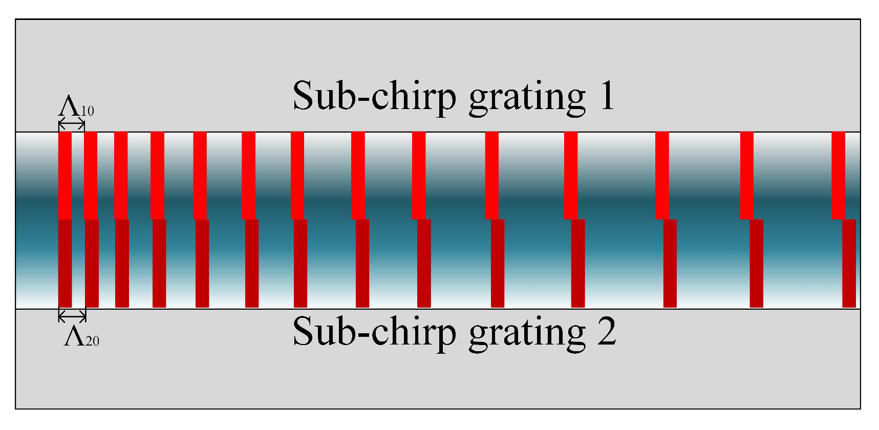
The 2D chirped fiber grating structure has two linear chirped fiber gratings; the structural diagram is shown in
Figure 1.
Two subchirped gratings are written at the same position of the fiber core without any overlap. The effective refractive index of the optical fiber core is
, the initial periods of the two subgratings are
and
, the chirp rate is
C, and the refractive index modulation amplitude is
. With these variables defined, the refractive index distribution in the core of the 2D chirped fiber grating can be calculated with Equation (
1), as follows:
where
and
, which are calculated using Equation (
2), are the periods of the two subchirped fiber gratings.
The longitudinal distribution of the refractive index is obtained as a linear superposition of the two chirped fiber gratings with the equivalent refractive index treatment [
9], as follows:
To obtain the mechanism for the refractive index modulation, Equation (
3) is reformulated to obtain Equation (
4):
where
and
denote the fast and slow variables of the modulation cycle, respectively.
As shown in
Figure 2, the superimposed refractive index modulation function has an envelope shape, and the slowly varying period corresponds to the period of the envelope. When the refractive index modulation increments of the two subchirped gratings exactly cancel, the superposition diagram shows a crossover point, which is equivalent to a
-phase shift at the same point.
In uniform 2D fiber gratings, refractive index modulation exists in both the longitudinal and transverse fibers according to the fabrication characteristics. The refractive index modulation is periodic in the longitudinal direction and a step function in the lateral direction. This result can be accurately explained by using traditional modal coupling theory in the longitudinal direction. The effective refractive index method can be applied in the lateral direction, resulting in the existence of subgratings with different periodic wavelengths that change the DC effective refractive index of the other subgratings. To date, strict modal coupling theory has not been used to investigate the spectral characteristics of this type of fiber grating. For nonlinear fiber gratings, the transmission matrix method and the thin film theory-based multilayer method are typically adopted. These two methods are essentially equivalent to modal coupling theory. However, to use the modal coupling equation to obtain the transmission matrix of a uniform subgrating segment in the transmission matrix method, the period of each small segment must be several times the period of the grating. Thus, this method cannot be used for multiple uniform 2D gratings. In contrast, the multilayer film method divides the fiber grating into multilayer films in the longitudinal direction, with the refractive index of each film replaced by a constant value. The transmission characteristics of each film layer are analyzed and superimposed according to thin film theory. This method can easily be applied to analyze the structure of a 2D fiber grating.
Figure 2.
Schematic diagram of the refractive index modulation of a 2D chirped fiber grating.
Figure 2.
Schematic diagram of the refractive index modulation of a 2D chirped fiber grating.
The multilayer film method regards the 2D fiber grating as multiple films, with the number of films determined by the modulation of the refractive index. Since the first-order Taylor expansion of a rectangular function is a cosine function, when a rectangular function is used to approximate a cosine function, the multiple of the amplitude changes but the phase remains constant. The greater the number of films, the more accurate the calculated results.
In this paper, the thickness of each film layer is assumed to be twice that of the fast changing period. The refractive index is assumed to be constant within each film. The transmission matrix of each film layer can be obtained according to thin film theory, and the transmission matrix of the entire grating can be found by multiplying the various stepwise thin film transmission matrices; then, the spectral characteristics are determined by using the boundary conditions.
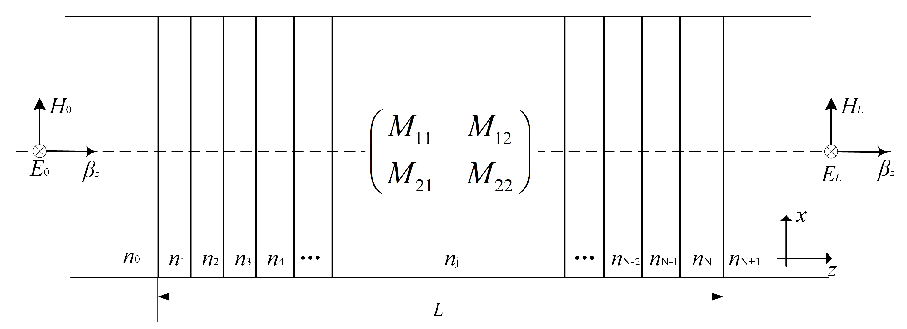
By assuming that the 2D chirped fiber grating is divided into
N-segment films, as shown in
Figure 3, Equation (
5) can be obtained according to film theory [
24,
27].
For a monolayer film, the input and output fields are connected by the transmission matrix of the optical film, which is expressed in Equation (
6).
The expression for each component of the transmission matrix [
24] is shown in Equation (
7):
where
is the thickness of the film layer,
is the refractive index of the
j-th film, and
is the propagation constant along the
z-axis within the
j-th film, i.e.,
, where
is the incident wavelength.
Figure 3.
Schematic diagram of the multilayer film transfer matrix.
Figure 3.
Schematic diagram of the multilayer film transfer matrix.
Assuming that the field amplitude incident on the two-dimensional fiber grating is
, the light wave at the incident end includes the original incident light wave and the reflected light wave, and the light wave at the initial end only includes the transmitted light wave, i.e., the electric field and magnetic field on both sides in Equation (
5), can be written as:
The recurrence relation of the above Formula (5) can be obtained
According to the total transmission matrix, the reflection and transmission coefficients at the incident interface can be calculated using Equation (
10):
where
. The reflectivity and transmittance can be calculated as
and
, respectively.
3. Simulation Results and Discussion
In this study, 2D chirped fiber gratings with effective refractive indices of 1.46, center periods of 532 nm and 532.15 nm, refractive index modulation depths of
, lengths of 0.5 cm, 1 cm, and 2 cm and chirp coefficients of 2.5 nm/cm, 5 nm/cm and 7 nm/cm were selected. The simulated reflection spectra based on the matrix method described above are displayed in
Figure 4.
There are multiple resonant peaks within the bandwidth of the chirped fiber grating, and the width of the resonance spectrum is equidistant. This is consistent with the spectral line characteristics of the 2D chirped fiber grating observed in the experiments. The preliminary simulation results demonstrate that the mode coupling theory and the transmission matrix method are feasible for studying 2D fiber gratings.
Figure 4a–c presents the changes in the spectrum for chirp coefficients of L = 0.5 cm, 1 cm and 2 cm, respectively. The larger the chirp coefficient is, the wider the spectral interval of the spectrum. Furthermore, the resonant wavelength increases with increasing chirp coefficient because the chirp coefficient affects the period at each point in the longitudinal direction. When the chirp coefficient is large, i.e., the period at the same longitudinal position is large, the chirp coefficient increases with increasing period beginning at central resonant wavelength, which can be calculated as
. The chirp coefficient is linearly proportional to the period, i.e.,
, where
C is the size of the chirp determined by the chirp coefficient, with
, and
z is the position of the second resonance point where the phase shift occurs, as shown in
Figure 5a for
m. Thus, the expression for the resonant wavelength can be obtained, as shown in
Figure 5a. The resonant wavelength is linearly related to the chirp coefficient and independent of the length of the grating.
The figure shows that the chirp coefficient affects both the resonant wavelength and the resonant spectral line spacing (FSR). As shown in
Figure 4d, as the chirp coefficient increases, the resonant spectral linewidth increases linearly. The error in the experimental simulation is small, especially when L = 0.5 cm. The relatively large error is due to the accuracy of the simulation because only two resonance peaks are observed.
Figure 5.
Influence of the chirp coefficient on the resonance wavelength. (a) Refractive index distribution of the 2D chirped fiber grating for L = 1 cm; (b) Second resonance wavelength at different chirp coefficients for L = 1 cm.
Figure 5.
Influence of the chirp coefficient on the resonance wavelength. (a) Refractive index distribution of the 2D chirped fiber grating for L = 1 cm; (b) Second resonance wavelength at different chirp coefficients for L = 1 cm.
To study the influence of different refractive index modulation depths on the spectral characteristics, three identical gratings with modulation depths of
,
and
were selected. The results are shown in
Figure 6.
Figure 6a shows the spectral output for different refractive index modulation depths.
Figure 6b,c show enlarged views of the shaded area in
Figure 6a. These figures indicate that refractive index modulation affects the peak reflectivity of the resonance but not the resonant wavelength and its width.
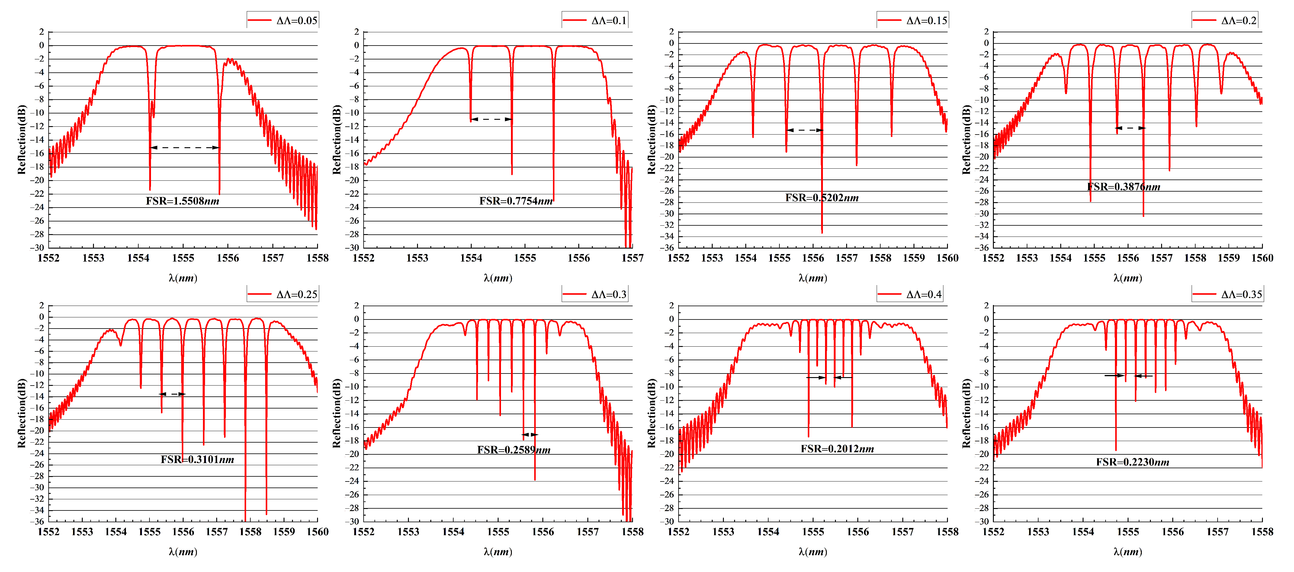
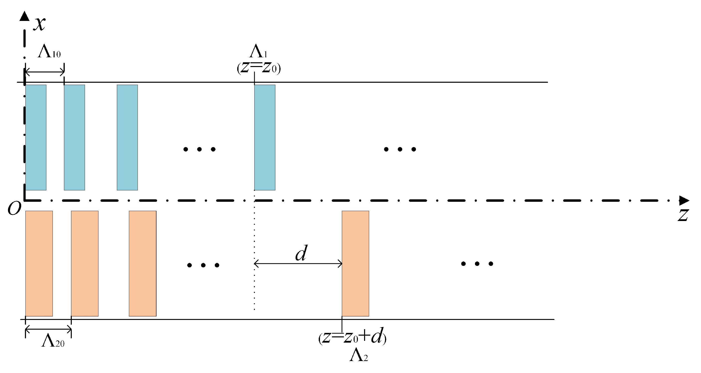
Figure 7 shows the spectral output diagrams for various initial period differences. The resonance width of the spectral output is clearly related to the initial period difference. Therefore, we analyzed the resonance width of the 2D chirped fiber grating, as shown in
Figure 8. It was assumed that the reflection wavelengths of the two subchirped fiber gratings were the same at the
z position of subchirped grating 1 and the
position of subchirped grating 2. At this point, the two reflection surfaces form an FP cavity with a cavity length of
d, and the relationship given in Equation (
11) is obtained.
The resonant cavity length of the
cavity can be calculated as follows:
According to the expression for the resonant width of the FP cavity [
28],
, we find that
where
Based on Equation (
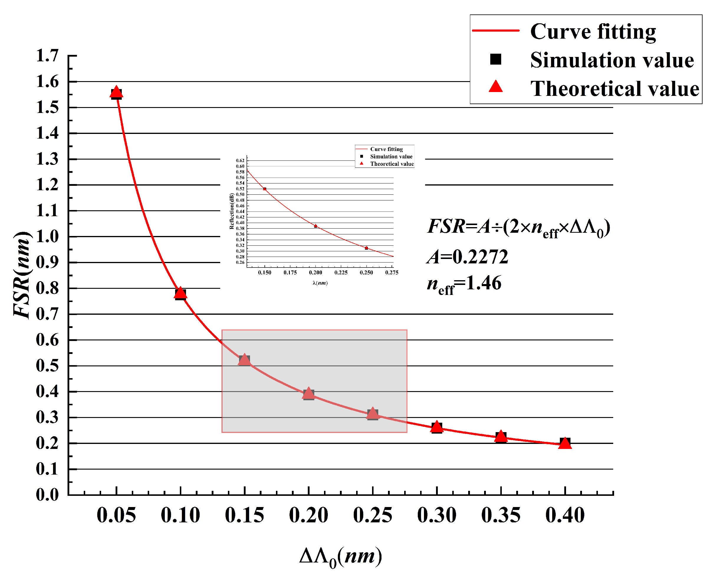
13), the curve for FSR versus
was obtained by simulating the spectra of 2D chirped fiber gratings with period differences of 0.05 nm, 0.1 nm, 0.2 nm, 0.25 nm, 0.3 nm, 0.35 nm and 0.4 nm, as shown in
Figure 9. The simulation results are consistent with the theoretical analysis, which indicates that the multilayer analysis-based simulation method is effective for this type of 2D fiber grating.
In summary, the main factors that affect the resonant width of a 2D chirped fiber grating are the chirp coefficient and the initial period difference. When a 2D chirped fiber grating is designed, the center wavelength of the grating bandwidth should first be determined according to the application requirements; then, the chirp coefficient should be fixed to determine the grating length L based on the passband width; and finally, the initial period difference should be determined according to the required resonant width. This method is useful for designing multiwavelength filters with required resonance intervals.
Figure 7.
Reflection spectra for 2D chirped fiber gratings with different initial period differences.
Figure 7.
Reflection spectra for 2D chirped fiber gratings with different initial period differences.
Figure 8.
Schematic diagram of the resonant width for a 2D chirped fiber grating.
Figure 8.
Schematic diagram of the resonant width for a 2D chirped fiber grating.
Figure 9.
Trend diagram and curve for the FSR variation with the initial period difference for a 2D chirped fiber grating.
Figure 9.
Trend diagram and curve for the FSR variation with the initial period difference for a 2D chirped fiber grating.
4. Experimental Comparison Analysis
The abovementioned 2D chirped fiber grating was fabricated by the phase mask method with a 2D spatial encoding phase mask with two parallel periodic fringes. With this phase mask, the functional complex optical elements can be engraved in the same region of the fiber core simultaneously.
In the experiment, a 248 nm KrF excimer laser with 160 mJ energy and 30 Hz duration output pulse power was used to write the 2D chirped fiber gratings, as shown in
Figure 10. The 248 nm KrF excimer laser with a pulse energy of 160 mJ and a repetition rate of 30 Hz is collimated through cylindrical lens 1, the slit which is used as a spatial filter to control the width of the beam and cylindrical lens 2, respectively. The cylindrical lens 3 focuses the rectangular shaped beam onto the fiber core. The optical fiber to be inscribed with its coating layer removed is clamped using a clamping system that is mounted on a mechanical stage with 5 degrees. The structure of the 2D spatial coding mask is mainly composed of two periodic structures and a gap, in which the width is 1um. Since the fiber is close to the mask, the distance between the two is much smaller than that after the column. Fresnel near-field diffraction [
29] occurs when the light shaped by the lens is irradiated on the mask. The amplitude distribution of the diffraction pattern passing through the cylindrical lens 3 and the mask is:
where
A is the amplitude of light wave incident on the cylindrical lens 3, which is generally normalized,
f is the focal length of the cylindrical lens,
d is the distance from the mask to the cylindrical lens 3,
P is the pupil function of the cylindrical lens, rect represents a rectangle function,
and
represent the period of the two masks, respectively, and
z is the distance from the receiving screen to the mask.
is the half width of the single-period structure,
is the gap between the two periodic structures and
nm is the wavelength of the incident laser. The 2D phase mask is placed close to the fiber; however, it is not in contact. The horizontal gap of the mask is adjusted to the center of the fiber core, as shown in
Figure 11.
The laser is shaped and focus to project two chirped periodic structures and a gap between them onto the fiber to inscribe a 2D CFBG. When there is a small angle between the fiber axis and the gap line of the 2D phase mask, the tilted line can be observed on the screen placed behind the fiber in the +1 and −1 diffraction stripes and can be adjusted accordingly. A broad-band light source is connected to one end of the fiber and the fiber output end is connected to an optical spectral analyzer to monitor the spectrum of the CFBG in the inscription process. The vertical position of the fiber can be fine-tuned until the FBG spectrum is symmetric to ensure the distribution of each periodic structure on the fiber core is symmetric. It is worth mentioning that this FBG fabrication system shown in
Figure 10 is a typical setup other than the specially designed 2D phase mask, and more stringent alignment is required in vertical position. According to the above process, a 2D CFBG-like
Figure 1 with a bandwidth of 12 nm can be successfully inscribed on a single-core fiber.
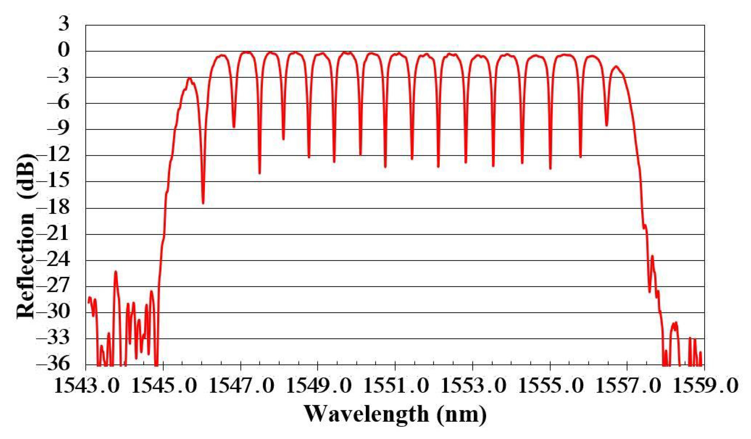
The optical fiber adopts a widely used single-mode SMF-28e fiber (core refractive index of 1.4682 and cladding refractive index of 1.4629). The chirp coefficient of the 2D spatial mask is 2.5 nm/cm, and the minimum periods for subchirp grating 1 and subchirp grating 2 are 526.372 nm and 526.486 nm, respectively; the grating length is 4 cm, and the insertion loss of each connector is approximately 4 dB. The spectral response of the 2D chirped fiber gratings measured using a spectrometer is shown in
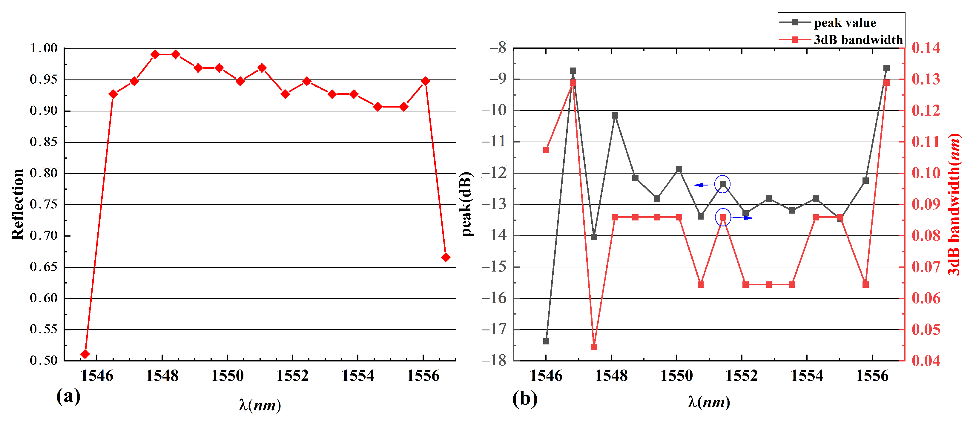
Figure 12. The reflection spectrum shows that there are 17 wavelengths for the transmission peaks in the passband of the grating. The peak size and 3 dB bandwidth for each transmission peak are shown in
Table 1.
Figure 13 show that the maximum transmission peak reaches 17.33 dB, and the average FWHM is 0.0834 nm. Furthermore, it shows that the 2D CFBG has 15 wavelength channels with reflectivity over 90% except for two wavelengths at the edges. This characteristic is of great importance for many important applications such as narrowband multi-wavelength filters and high power fiber lasers. The compact structure and high reflectivity of the 2D-CFBG make it easy to integrate for a wide range of applications in large-scale fiber optic communications.
A comparison of the resonance peak intervals obtained from the theoretical simulation and experiment is shown in
Figure 14. The simulated and experimental resonance intervals are clearly comparable. The peak difference at the transmission peak is mainly due to insertion loss, while the other minor differences may be due to the inhomogeneity of the UV laser beam, minor defects in the drawing of the single-mode fiber and errors in the grating length during grating fabricating.
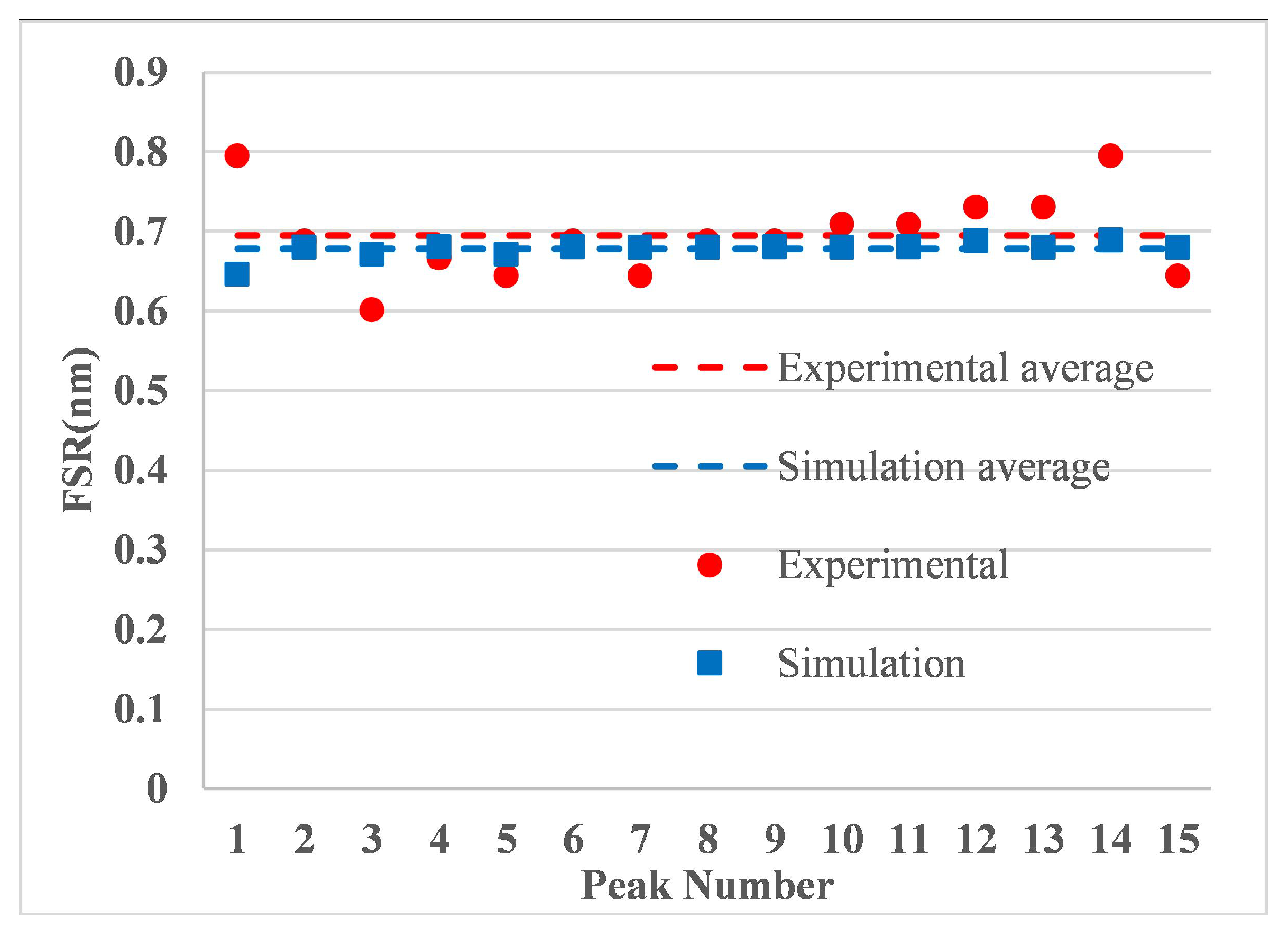
A comparison of the theoretical simulation and experimental shearing peak spacing is shown in
Figure 15. The simulated and experimental resonance intervals are essentially consistent. The average FSR for the simulated and experimental intervals are 0.6947 nm and 0.6781 nm, which are round 88 GHz at 1.55
m, respectively, and the relative error is 2.45%.
Table 1.
Peak reflectance and FWHM at different transmission peaks in the reflection spectrum of a 2D chirped fiber grating.
Table 1.
Peak reflectance and FWHM at different transmission peaks in the reflection spectrum of a 2D chirped fiber grating.
| Peak | Peak Value (dB) | FWHM (nm) | Peak | Peak Value (dB) | FWHM (nm) |
|---|
| 1 | −17.37 | 0.1074 | 9 | −12.34 | 0.0859 |
| 2 | −8.728 | 0.1289 | 10 | −13.28 | 0.0645 |
| 3 | −14.04 | 0.0445 | 11 | −12.81 | 0.0645 |
| 4 | −10.15 | 0.0859 | 12 | −13.19 | 0.0645 |
| 5 | −12.15 | 0.0859 | 13 | −12.81 | 0.0859 |
| 6 | −12.81 | 0.0859 | 14 | −13.47 | 0.0859 |
| 7 | −11.86 | 0.0859 | 15 | −12.24 | 0.0645 |
| 8 | −13.38 | 0.0645 | 16 | −8.633 | 0.1289 |
Figure 13.
(a) Peak reflectivity of the 17 wavelength channels of the 2D CFBG. (b) The peak value and 3dB bandwidth at different transmission peaks in the reflection spectrum of a 2D CFBG.
Figure 13.
(a) Peak reflectivity of the 17 wavelength channels of the 2D CFBG. (b) The peak value and 3dB bandwidth at different transmission peaks in the reflection spectrum of a 2D CFBG.
The two main applications of 2D chirped fiber gratings are mainly divided into passive and active systems. The 2D CFBG in this paper has a reflectivity greater than 90% and a FWHM of about 0.0834 nm per channel, which allows it to be used as a multi-wavelength narrowband filter for WDM systems, which requires low insertion loss and high isolation of the light wave after passing through the grating. When used in active systems, the multi-channel comb filter can be used as a mode-selective resonant cavity for multi-wavelength fiber lasers; one is to directly inscribe the 2D CFBG directly on the active fiber (such as erbium-doped fiber and erbium-ytterbium co-doped fiber, etc.) to form a narrow linewidth multi-wavelength laser with linear cavity, and the bias-preserving fiber or self-injection locking can be used to suppress the possible problem of mode instability in the mode-selective cavity. Moreover, it can be combined with Raman fiber laser pumping nonlinear fiber; using the comb filter can realize multi-wavelength simultaneous excitation of the multi-wavelength Raman fiber laser. Several studies have been conducted on multi-wavelength fiber lasers [
30,
31] using comb filters as mode-selective devices.
Figure 14.
Comparison of the experimental (solid line) and simulated (dashed line) reflectance spectra for the 2D chirped fiber grating.
Figure 14.
Comparison of the experimental (solid line) and simulated (dashed line) reflectance spectra for the 2D chirped fiber grating.
It is worth noting that the most significant advantage of this method is that the grating is completed in one inscription exposure, the spectral consistency among the subgratings is better, and it avoids the effect of repeated exposure on the spectrum of the previous inscribed grating compared to the overlapping inscription technique.
Figure 15.
Comparison of the experimental and simulated FSR for a 2D chirped fiber grating.
Figure 15.
Comparison of the experimental and simulated FSR for a 2D chirped fiber grating.
In summary, the experimental results demonstrated that the thin film theory-based multilayer method can be employed to accurately analyze and design 2D fiber gratings. By changing the initial period difference and the grating length of the subchirped grating, a multiwavelength filter resonator can be precisely designed. In addition, a 2D space mask can be used to write the 2D chirped fiber gratings with a simple method that provides good output spectral characteristics. In the future, this method is expected to be applied to the realization of a laser mode selection resonator and a dispersion compensator for multiwavelength fiber lasers.
5. Conclusions
In conclusion, we have demonstrated a simple method for fabricating compact 2D chirped fiber gratings using spatial masks, and the spectral properties were analyzed based on thin film theory. First, the concepts of 1D fiber gratings were extended to 2D fiber gratings, and the spectral characteristics and resonance interval of two chirped fiber gratings were written onto two subchirped fiber gratings at different transverse positions in the same fiber core. The spectral output was adjusted by controlling the initial period difference and the grating length when the chirp coefficient was constant. Second, a multiwavelength filter resonator with 17 Moire fringe outputs was successfully written onto a single-mode fiber using a spatial phase mask. The passband has a high reflectivity, which is useful for applying mode selection resonators to multiwavelength fiber lasers. Finally, when the same parameters were applied, a comparison of the experimental and theoretical simulation results demonstrated that the reflection spectrum curves are consistent, and the error in the resonance peak width was only . Thus, we demonstrated that the multilayer method is feasible for studying the spectral characteristics of this type of fiber grating. The 2D chirped fiber grating has several advantages, including a compact structure, multi-channel, strong consistency, precise control, simple fabricating method and good reproducibility. In the future, mode-selecting resonators for multiwavelength fiber lasers are expected to be widely utilized in dense wavelength division multiplexing systems.

