Abstract
Visible Light Communication (VLC) is an important emerging choice for high-speed wireless communication. In this perspective, light-emitting diodes as illuminators will be modulated to transmit data simultaneously. However, the receivers bring severe difficulties due to cost, response time, and sensitivity with a wide Field Of View (FOV). To avoid these problems, one approach is to apply a large area photodetector; however, this solution is slow and costly. Another method is to focus light on a fast photodetector by optical components, but the photodetector’s FOV decreases, resulting from the conservation of etendue. Another option is Luminescent Solar Concentrators (LSCs). This paper demonstrates a novel shape of LSC with advantages such as inexpensive, fast response time, small antenna area for VLC purposes with significant geometrical gain, FOV, and ultra-broad bandwidth. It does not require any complex tracking system and active pointing but, due to its tiny size, it can also be adapted in integrating and mobile devices. Numerical simulation is done using Monte-Carlo raytracing, and the results are demonstrated in the spectral domain. The optical efficiency of the proposed antenna is obtained at 1.058%, which is about 0.4% better than the efficiency levels reported in other works, and the geometric gain of the antenna is reported to be 44, which is significant.
1. Introduction
In the contemporary world, an extension of numerous digital technologies has made wireless technology an essential means of connection [1,2]. Wireless communication technology is one of the flourishing fields of communication through which people can communicate from anywhere and at any instant using electromagnetic (EM) waves wirelessly. Hence, it has become a significant transmission medium [1,3]. Transmission applications in wireless networks have caused unexampled solicitations. Therefore, supplying high-performance wireless transmission is of great importance [4]. Although Radio Frequency (RF) communication as a subset of wireless communication is widely used for an extensive range of applications due to its small electromagnetic (EM) interference and decent coverage, the network traffic has experienced incredible congestion because of the excessive users and heavy data-hungry applications [3,5]. Over time, it has faced some challenges, such as increasing demand for high Quality of Service (QoS), achieving a high data rate (beyond Gbps toward Tb/s regime), limited channel capacity, limited bandwidth, and the emergence of fifth- and sixth-generation (5G and 6G) networks [5,6,7,8]. As its management by the limited RF spectrum has become a growing concern, there was a severe need to develop a new technology to avoid the defects of previous technologies. In this regard, Optical Wireless Communication (OWC) technology was proposed as an alternative technology, especially for indoor communications [9], which transmits data using light pulses instead of radio waves [3].
OWC works in the optical region of the electromagnetic (EM) spectrum (300 GHz to 30 PHz), which is license-free and nonhazardous. Hence, it provides a high data rate, high capacity, broad bandwidth (in range of THz), security, and safety acute in the RF region [1,3,6,8]. Additionally, OWC possesses many other features, including high energy efficiency and low cost [1]. At first, OWC focused on wireless infrared communication. Then, it extended to the visible region of the EM spectrum, and it was called Visible Light Communication (VLC) [8]. VLC is an attractive developing field in OWC technology to fulfill the RF-based wireless fidelity (Wi-Fi) [10,11]. Through it, data are transmitted by intensity modulation of an optical source operating in the visible range of the EM spectrum (400–800 THz) at a very high rate [5]. The human eye cannot detect pulses and preserves them as a constant light [12]. Nowadays, revolutionary choices for optical sources are Light Emitting Diodes (LEDs) because not only are they able to illuminate an area thanks to their low energy (they can reduce energy consumption by 80% [3]) and higher lifetime, but also they can transmit data with less cost and a smaller carbon footprint [13]. Since serious environmental problems such as energy shortage, greenhouse gases emission, and global warming are growing [14,15,16], using LED as a source of VLC on the global scale can play a helpful role in preventing the condition from getting worse. This is why VLC has been very successful in attracting many research interests [13]. To indicate the importance of VLC, some examples can be emphasized, such as underwater VLC [17], high-speed indoor VLC [18], Non-Orthogonal Multiple Access (NOMA) for VLC systems [19], Power Domain Non-Orthogonal Multiple Access (PD-NOMA) for 6G networks [20], intelligent reflecting surfaces to aid VLC [21] and cooperative and non-cooperative relying on VLC channels [22].
To accomplish a VLC-based system, a modulated light source and a receiver are also needed. Antennas, therefore, are important and inseparable parts of VLC [4,23]. There are two substantial quantities in VLC: bandwidth and signal-to-noise ratio (S/N) [3,9]. In a high-speed VLC data link, the combination of a large signal-to-noise ratio and high bandwidth is crucial, not only in transmitters but also in receivers. Principally, these two factors determine the channel capacity of a VLC system [11]. Since VLC uses the illuminator LED as a data carrier and its bandwidth is limited to 20 MHz or less [24], it will restrict the bandwidth of the VLC system, so achieving a large bandwidth using existing LED technology is out of reach. Thus, improving the latter quantity, a high signal-to-noise ratio, is of great importance in VLC. Obtaining a large signal can be possible by collecting a large fraction of the light from a transmitter. In this case, there is a need for a large photodetector, which would normally have a slow response time and be expensive [9,11].
On the other hand, a typical photodetector with a bandwidth of GHz level has an active area of around 1 mm2 or less. Thus, the common way to improve the SNR in this much smaller photodetector is focusing the light onto it using an optical element that works based on reflection and refraction (for example, an optical lens or compound parabolic reflectors), thereby conserving the etendue in geometric optics. The conservation of etendue declares that if the wavelength of an optical system does not change, the maximum concentration gain of the system (Cmax) and field of view (FOV) are related inversely by Cmax = n2/sin2(θ), where n is the refractive index of the concentrator and θ is the acceptance angle that describes the FOV (range of solid angles for which the photodetector accepts light) [9,11,25]. However, if the wavelength of the optical system changes, etendue does not need to be conserved, and it is possible to obtain both high concentration gain and a wide FOV simultaneously [25,26]. In this regard, non-imaging optical concentrators called Luminescent Solar Concentrators (LSCs) have emerged recently as a reassuring receiver technology to realize VLC-based systems. Originally, they were fabricated to gather and concentrate the solar energy efficiently and guide it toward solar panels attached on all side edges of the LSC at an affordable cost.
Apart from photovoltaics, they attracted a wide range of interests for numerous applications, including microreactors [27], greenhouse coatings [28], dark-field imaging [29], dynamic systems (where the arrival time of photon is of the essence) such as image recording and movement detection technologies [30] and especially as an antenna in VLC-based systems very recently [25]. In the latter case, LSC has been made from a transparent host matrix doped with fluorophores. They are recommended to collect both direct and diffuse light of modulated LEDs from wide FOV in VLC systems. Then, fluorophores absorb the incident light and re-emit it at a longer wavelength by a down conversion [31]. This wavelength change is known as the Stokes shift. Thus, high concentration gain, a wide FOV, and consequently a high signal-to-noise ratio are accessible simultaneously without any other limitation [7]. The general schematic of an LSC has been illustrated in different references. So far, several shapes and sizes of waveguides and different types of fluorophores and host matrixes have been investigated to evaluate LSC performances [32] in terms of optical efficiency and FOV [25]. Since they can concentrate both direct and diffuse intended light, no tracking system is required [32,33]. LSC with a communication purpose includes a thin host matrix doped with fluorophores and the photodetector of receiver mounted on one specific edge. First, fluorophores absorb incident light signals from a large surface area, and secondly they re-emit photons at lower energy. The difference between refractive indices of the host matrix and surrounding medium causes the newly generated photons to be waveguided or retained inside the LSC because of the total internal reflection (TIR) phenomena.
TIR leads to trapping these re-emitted photons inside the optical waveguide and concentrating them onto the edge of the LSC device [31]. Eventually, part of the photons is collected by a photodetector attached to the specific narrow edge or small end facet of the LSC [11,32]. Since the 1970s, various types of fluorophores have been applied to enhance the optical efficiency of the LSC [31]. Different types of fluorophores can be classified into organic dyes [34,35], lanthanide complex hybrids [36,37], perovskites [38,39] and Quantum Dots (QDs) [40,41]. Primarily, organic dyes, such as coumarin and rhodamine, are indicated as the high-performance fluorophores of LSCs owing to their large absorption coefficient, high photoluminescence quantum yield (PLQY), and good solubility [31,42,43]. Nevertheless, some unavoidable drawbacks of them including an unfriendly photodegradation effect and narrow absorption spectra affected their position. QDs, meanwhile, have significant pros over others, such as adjustable absorption and emission spectra, stability, a high quantum yield (QY), and a large absorption cross-section [32]. Most recently, wide research has been conducted focusing on LSCs in a variety of fields, such as photovoltaic systems, optical communication systems, and others.
In the photovoltaic field, H. Zhao et al. in 2018 perused two perovskite LSCs and utilized spin-coated carbon dot LSC in the tandem structure. For carbon dot, green-emitting perovskite, and the red-emitting perovskite layer, optical efficiency was 0.3%, 1.1%, and 1.65%, respectively. In the end, combining three layers in one tandem structure improved optical efficiency to 3.0% [44]. In the most recent research, M. R. Mirzaei et al. modeled LSC based on different QDs with dimensions of 60 × 60 × 1.25 cm3. The optical efficiency was written up as 11.8%, 13.8% and 31% for three different QYs (0.4, 0.6, and 1, respectively) [32]. On the other hand, different geometries have been studied in the communication field to increase optical efficiency, bit rate, and FOV. In 2016, Manousiadis et al. designed a dye-doped planar LSC sandwiched between microscope slides. FOV and data rate were reported as ±60° and 190 Mb/s, respectively [11]. In the meantime, in another research, Peyronel et al. demonstrated a ball-shaped fiber-based LSC, reporting the FOV of 3.9π and data rates of 2.1 Gb/s [45]. In Table 1, the properties of previous works are summarized. Considering the number of utilized edges, this work has achieved better results.

Table 1.
Summary of previous works.
A large surface sufficient for collecting light from a large FOV offers LSCs exemplary merits because they do not need any tracking systems and active pointing. These advantages lead to reduce cost and complexity and provide better adaptability with mobile devices such as wireless virtual reality headsets, quadcopters, etc. In any manner, there are still many shortcomings, especially about the efficiency of LSCs in optical communication that hinders their high performance. Up to now, many thermodynamic, theoretical, and light tracing models have been developed for modeling the LSC prototype devices, because theoretical simulation is an essential method to analyze and confirm the parameters of LSC prototype devices.
Monte-Carlo ray-tracing simulation is one of the common methods to model LSCs because of their presumptive nature, diverse possible outcomes, and greater flexibility. Among all, Monte-Carlo simulation as a numerical method has a cogent usage in the situations wherein variables have coupled degrees of freedom, or there is no deterministic algorithm to solve the problem. It possesses a generally accepted popularity in different sciences including physics, statistics, engineering, finance, project management, and mathematics [40].
This paper aims at presenting a promising and novel schematic for the optical antenna using LSCs based on graphene QDs. Optimistically, not only can it partially address the mentioned problems, but it also allows for the application of a very small photodetector that is very fast, sensitive, and cost-effective. Our approach in this paper is introducing a new shape of an antenna suitable for VLC to take advantage of various factors. First, LED as a light source is used to provide a high data rate, low energy consumption, a high lifetime, less cost, and a smaller carbon footprint. Second, LSC is the main structure for the antenna to achieve a wide FOV and high concentration gain (due to stokes-shift), and it does not need any tracking system and active pointing. Third, a new antenna shape is used to attach a small photodetector that is fast, sensitive, and cost-effective, and to reach high geometric gain. Fourth, small size and dimensions are used to be adaptable with electronic devices and integration systems. The proposed antenna is analyzed using Monte-Carlo ray-tracing simulation. Moreover, we have calculated the percentage of every event and extracted corresponding spectra. Additionally, we have simulated the bandwidth of the passive component theoretically. We anticipate that our results will be a turning point for future research on Graphene Quantum Dot (GQD)-based LSC devices for communication purposes.
The rest of this paper is organized as follows. First, in Section 2, we described the structure and shape of the proposed optical antenna and possible events that occur in it as well. Furthermore, the Monte-Carlo algorithm and followed steps were depicted in Section 2. Then, in Section 3, we provided related simulation results of the proposed scheme. Finally, a conclusion is drawn and future works are outlined in Section 4.
2. LSC Structure and Possible Phenomena
An optical antenna is assumed to have a semi-sharp shape in our proposed structure. The schematic diagram of the LSC configuration is demonstrated in Figure 1. The host matrix consists of polyvinyl alcohol (PVA), and Graphene Quantum Dots (GQDs) are embedded. Further, the photodetector of the receiver is placed on the tip of the antenna which is a small end facet of the LSC. The source of input light is a blue 450 nm LED, and it is irradiated on the front surface of the antenna. Generally, incoming photons are absorbed by GQDs and then re-emitted in a longer wavelength. Due to total internal reflection phenomena, the re-emitted photons can be trapped inside the waveguide. They are then guided toward the tip of the LSC, which will be further detected by a photodetector and converted into an electrical signal. Thus, the LSC plus the attached photodetector is a system to transmit light signal and convert it into electrical signals for data transmission purposes.
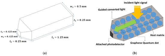
Figure 1.
Schematics of the proposed optical antenna. (a) Dimensions of the proposed optical antenna. (b) Configuration of components in the optical antenna (host matrix, Graphene Quantum Dots (GQDs), photodetector, incident light, and guiding light).
Different phenomena occur when a light beam is an incident on the front surface of LSC. Those are illustrated in Figure 2. First, a photon may be reflected from the top surface without even entering the LSC due to the difference in refractive indices of the two mediums. After entering the remaining photons, there is a possibility that either a photon is absorbed by the GQDs or passes through the LSC without being absorbed. The absorbed photon may be re-emitted by GQDs at an angle incidence greater than the critical angle, resulting in Total Internal Reflection (TIR), and, finally, the photon may reach the photodetector after some TIR. Furthermore, there is a possibility that the photon will be re-emitted in a direction resulting in the direct collection at the tip of the LSC without any prior TIR.
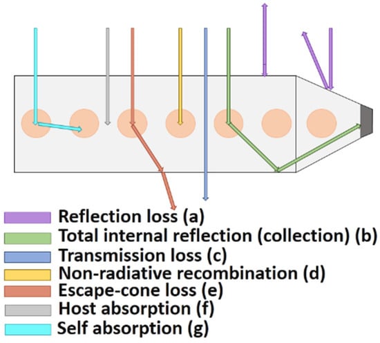
Figure 2.
Physical process in optical antenna.
Moreover, some percentage of the newly emitted photon escapes from LSC due to escape-cone loss. Additionally, the re-emitted photon can be re-absorbed by the adjacent GQDs; this mechanism is known as self-absorption. Further, the absorbed photon may be quenched by non-radiative decay. Rarely, the host matrix can absorb and quench the photon; however, due to its low probability of occurrence, it will be ignored in this paper. The process can be simulated by the Monte-Carlo method that will be described in the next section.
LSC Monte-Carlo Ray-Tracing Simulation
The Monte-Carlo technique is a versatile statistical approach for modeling the propagation of photons through a system. The Monte-Carlo simulation works based on mathematical relevant equations such as the Beer–Lambert law, Snell’s law, Fresnel law, and empirical data such as the absorption spectrum, photoluminescence spectrum, and quantum yield of fluorophores. The ultimate fate of each photon is determined via this simulation under physical phenomena such as reflection, absorption, emission, and transmission procedures. Using this method leads to the avoidance of complex radiation transfer equations. Monte-Carlo simulation is expanded to model and optimize the operation and performance of LSCs. The algorithm used to create discussed Monte-Carlo simulation to model the proposed device is shown in the flow chart in Figure 3. Each time the algorithm is run, only one randomly generated photon is accounted for. The goal of this simulation is to detect whether the single photon will be collected or lost. Moreover, it can determine the type of loss among the probable losses, such as reflection, non-radiative recombination, transmission, and escape-cone loss.
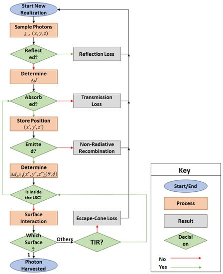
Figure 3.
Monte-Carlo algorithm for numerical simulation.
The Monte-Carlo algorithm applied to model the proposed LSC (Figure 4) is depicted as follows [46,47]:
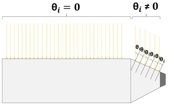
Figure 4.
The incident light on the optical antenna.
- The first step is to sample the wavelengths of incident photons from the spectrum of a 450 nm blue LED. This sampling process dawns on generating a Probability Density Function (PDF) [32] of the spectrum of the LED directly. Figure 5a represents the PDF of the 450 nm blue LED.
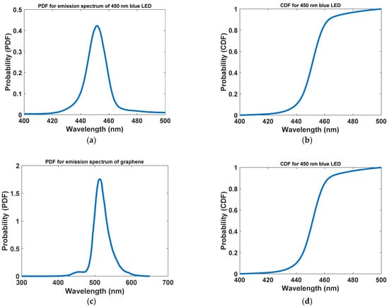 Figure 5. Probability density function (PDF) and cumulative distribution function (CDF) for blue 450 nm LED (a,b) and graphene quantum dots (c,d) respectively.
PDF = (Distribution/Area of the Curve)
Then, the PDF is converted to the Cumulative Distribution Function (CDF) [32], through which the wavelength of each photon is generated using the inverse transform sampling method.
The CDF is defined as the area of the PDF curve until the i-th term, to the whole area of the PDF. Equation (2) depicts the relation applied to calculate the area under the curve, where λj is the j-th term of the wavelength, and k is the wavelength vector’s length. Figure 5b points out the CDF of the 450 nm blue LED. In total, 100,000 initial photons with uniform distribution on the upper surface of LSC and flood illumination are assumed during this simulation. The upper flat surface of LSC encounters a typical incidence, while the upper inclined surface will have the incident light with a non-zero input angle. This is calculated by using trigonometric relations.
- 2
- Some percent of initial photons are reflected from the upper surfaces of LSC results from the different refractive index for waveguide and the surrounding medium. In this work, it is assumed that the LED is TE polarized. Hence, the probability of reflection is calculated from Fresnel reflection equations [48] as Equation (3).
Since nAir = 1, and nLSC is assumed to be the refractive index of PVA, which is approximately 1.49 in the visible light region [49], totally about 4% of primary photons are reflected from the top surface, regarded as reflection loss.
- 3
- Once a photon enters the LSC, it must be determined whether absorption occurs. To achieve such a property, the Beer–Lambert law is an adequate tool to work out the probability of a photon that is absorbed through the absorption path length. Fractional absorbance, A [50], is a CDF and gives the probability that a photon will be absorbed.
Absorption probability is specified by a random number in this simulation. By introducing , which is a random number in the range of [0,1], the relation can be written as Equation (7) [50].
where Δd represents the distance, a photon will travel before being absorbed. If the Δd found is smaller than the LSC thickness and simultaneously its wavelength is valid in the absorption region of the GQDs, QGDs will absorb the photon. Otherwise, it will pass through the LSC without any absorption known as transmission loss. The position of the absorbed photon is stored for the rest of the simulation.
- 4
- In this step, it must become clear whether GQDs would emit the absorbed photon or not. It is done according to the quantum yield, which is defined by the ratio of the emitted photons to the total number of the absorbed photons [51], and a randomly generated number (β) between 0 and 1. If β < QY, the photon would be re-emitted. Otherwise, it would undergo non-radiative decay known as non-radiative recombination loss [31]. After re-emission, the new position of the photon must be updated. Moreover, the emission angle is obtained randomly (uniform distribution), and the wavelength of the new photon is obtained simply from the PDF and modeling of the emission spectrum of the GQDs. Figure 5c,d demonstrate the PDF and CDF for the emission spectra of GQDs. The crossed distance by the re-emitted photon is given in Equation (8) [50].
Moreover [50],
- 5
- Now, it must be checked if the newly generated photon is still inside the LSC structure. If the answer is yes, the previous steps must repeat the photon. If not, the photon must interact with LSC surfaces.
- 6
- The last objective is to determine the interacted surface. If the photon reaches the tip surface of the LSC, it will be harvested by the photodetector. Otherwise, two separate scenarios can be the outcome if it hits the other surfaces. First, the photon is reflected due to TIR, and whether it returns into the LSC or interacts with another surface is determined. Second, the photon escapes from the interacted surface and is consequently lost due to escape-cone loss.
The steps mentioned above are repeated for all the 100,000 initial photons one by one to complete the simulation and trace the fate of each photon. To evaluate the performance of the LSC, we define some relations as follows. The optical efficiency [32] of the LSC can be illustrated as Equation (10).
η = (Collected Photons/Incident Photons)
Geometric gain is another parameter to assess the concentration of the LSC, although we have defined optical power efficiency until now. Geometric gain [32] is described as Equation (11). It measures the maximum possible photon flux concentration of an LSC when all the other factors are ideal.
where ALSC is the total area of the upper faces of the LSC (both flat and inclined) and APD is the area of the attached photodetector. Ultimately, the product of optical efficiency and geometric gain is defined as optical flux gain [32], as written in Equation (12).
3. Results and Discussion
To realize a VLC antenna, LSC technology has been used. The host matrix material was PVA with a refractive index of 1.49, and for the fluorophores of the structure, GQDs have been considered. We designed the size of the GQDs experimentally to obtain its photophysical characterization, including absorption and photoluminescence spectra and QY. The resulting absorption and photoluminescence spectra are exhibited in Figure 6. As is apparent from the figure, GQDs can absorb a wide range of the visible band, convert it to around 520 nm by stokes-shift and emit only the green color. This means that, in addition to the 450 nm blue LED, the designed GQDs also can absorb other colors. Thus, our suggested antenna design will have a greater degree of freedom to work with several colors of LEDs used in ambient lighting. Additionally, QY of GQDs has acquired 0.99 thanks to the synthesis method, so this is considered throughout the study.
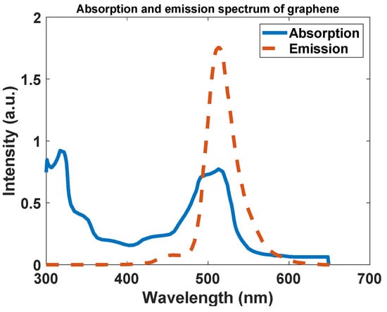
Figure 6.
Absorption and emission spectrum of graphene.
Monte-Carlo ray-tracing simulation requires five different input parameters, including LSC waveguide dimensions, refractive indices of LSC and the surrounding medium, quantum yield, concentration and absorption, and photoluminescence spectra of fluorophores. Depending on the synthesis methods, the quantum yields of fluorophores vary between zero and unity. In this study, we considered the dimensions as shown in Figure 1a. Moreover, we have assumed the refractive index of LSC constant and equal to the refractive index of the host matrix because the concentration of the QGDs is not high enough to change the refractive index of the host material. The concentration of GQDs is approximately 120 PPM and the surrounding medium is air.
After completing the simulation, according to Equation (10), the optical efficiency of the LSC is acquired at 1.058%. Meanwhile, geometric gain, which assesses the aspect ratio of the device and plays an inevitable role in the overall performance of the LSC is calculated from Equation (11) and is 44. The ultimate goal of designing an antenna using LSC technology is acceding to the cost-effective, sensitive, small, and fast antenna for VLC purposes. This objective can be fulfilled by geometric gain enlargement. Because the tiny end facet on which the photodetector is attached would be far smaller than the front surface of the LSC. In our structure, due to the geometry, it is possible to have an ultra-high geometric gain because the front surface of our structure is much larger than its tip surface and the export of the semi-sharp-shape LSC has a better match with high bandwidth photodetectors compared with the rectangular LSCs.
Nevertheless, the absorption and subsequently the output power of the LSC depend on the thickness of the LSC directly. Therefore, in a mandatory manner, optical power efficiency and energy flux gain have a tradeoff relation. To evaluate our proposed structure, we have tracked the fate of each interfering photon in the simulation.
According to the Monte-Carlo simulation, 3.887% of the initial 105 photons are reflected from the top surface of the LSC due to the refractive indices difference between the surrounding medium and the waveguide, which is known as reflection loss. Moreover, 3.728% of the photons entering the structure are passed through the LSC without being absorbed, which is called transmission loss. Finally, 92.385% of the leftover photons are absorbed by the GQDs. However, not all of these photons have a chance of finding a way to the exit aperture. In this regard, 10.865% of them are lost due to non-unity quantum yield, which is known as non-irradiative recombination. Additionally, the photodetector collected 1.058% of the absorbed photons. At the same time, 30.286% of the absorbed photons are exited from the other edges of the LSC. A total of 50.176% of the absorbed photons are lost due to escape-cone loss. We anticipate that, in future work, we could concentrate this amount of the photons toward the photodetector using the existence optical elements to enhance the optical efficiency extraordinarily. For instance, this can be achieved by attaching a 99% mirror on the other edges of the antenna. To make the percentages more comprehensive, we summarized the fate of each photon in Figure 7.
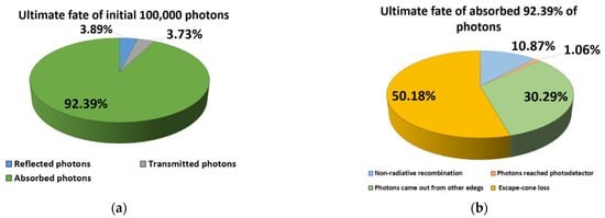
Figure 7.
The fate of photons after simulation. (a) Contribution of reflected, transmitted, and absorbed photons. (b) Contribution of losses (non-radiative recombination, escape-cone loss) and beneficial photons (reached the photodetector and other edges).
As a comparison with previous works, different indicators should be considered. For example, in photovoltaic applications, solar panels are attached to all edges of the LSC. This means that collected photons from all the edges are beneficial and converted to electrical power, while in communication applications the photodetector is attached on only one edge. In this way, the optical efficiency of the LSC will be reduced by at least a quarter of the solar LSCs (depending on the shape of the LSC). With all this, the optical efficiency of our structure is much better than the reported ones in [44]. This is because, if we include other edges of the LSC, its optical efficiency will be enhanced to 30.286%, whereas the most considerable reported optical efficiency was 3.05% with the tandem structure in [44]. For communication purposes, it is inadequate to use all the edges of the LSC because it needs more photodetectors, which are very costly, so the mentioned quantitative report was only for indicating the amount of improvement. On the other hand, in [32], 31% optical efficiency was written up due to the considerable size of the LSC, which is almost several hundred times larger than our proposed LSC. It is worth mentioning that, in the communication field, the smaller antenna, the better the installation of electrical appliances. Previous work [11] in the field of communication that has introduced an optical antenna had 0.612% optical efficiency based on its data resulting from Monte-Carlo ray-tracing simulation and Equation (10). Contrastingly, we have achieved an optical efficiency of 1.058% in this work, so about a 0.4% improvement is evident.
Meanwhile, we have extracted the spectra of the aforementioned event to analyze the structure visually. First off, the randomly generated initial photons spectrum is shown in Figure 8a. It is evident from the figure that the spectrum of the initial photons is bounded in the as same range as the 450 nm blue LED spectrum. The reflected and transmitted photons spectra are illustrated in Figure 8b,c, respectively. Furthermore, the spectrum of the absorbed photons is presented in Figure 8d. Following this, the quenched photons spectrum is exhibited in Figure 8e. In addition, sequentially, the spectrum of photons came out from all edges, and the spectrum of the harvested photons is pointed out in Figure 8f,g. The difference in peak position and the shoulder appearance is due to the self-absorption of the emitted light because of the overlap between the absorption and emission spectra of GQDs (see Figure 8h). This overlap also brings about a few wavelength differences between emission spectra of the graphene and collected photons spectra in the antenna. Since it is more important to have a broadband absorption spectrum for GQDs (see Figure 6) to make the antenna competitive with different color LEDs used in lightening, we forgive this little wavelength difference. To sum up, we summarized all the spectra in Figure 8i.
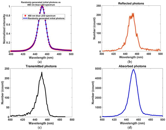
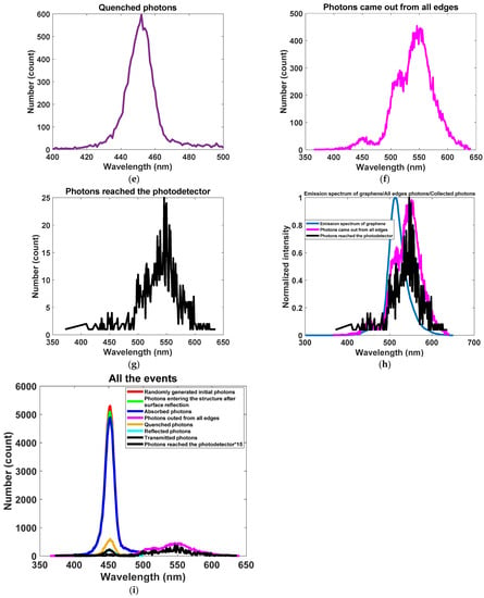
Figure 8.
Results after Monte-Carlo simulation. (a) Incident photons (randomly generated). (b) Reflected photons. (c) Transmitted photons. (d) Absorbed photons. (e) Quenched photons. (f) Photons came out from all edges. (g) Photons reached the photodetector. (h) Emission spectra of graphene collected photons, and photons came out from all edges in one figure. (i) All events in one figure.
At the last attempt, we computed the proposed structure’s bandwidth by applying a modulated input. During this simulation step, we have replaced the modulated spectrum of 450 nm blue LED instead of the non-modulated spectrum by applying a wide range of modulation frequencies. The non-modulated spectrum of 450 nm blue LED was shown in Figure 5a. In the time domain, the temporal response of the normal LED is as Equation (13), equivalent to Equation (14) after Fourier transforms to conveniently perform mathematical and simulation operations in the frequency domain.
Following these relations, the time-domain function and Fourier transform of the amplitude-modulated LED signal [52] are given as Equations (15) and (16), respectively, where m is the modulation index, which can vary between 0 and 1 [52]. We have assumed m = 0.2 throughout the simulation. Moreover, ωm is the modulation frequency. By applying a wide range of modulation frequencies (as shown in Figure 9), we have recorded the number of the harvested photons to make the bandwidth of our proposed structure evident. In this analysis, we only investigate the frequency response of the optical antenna.
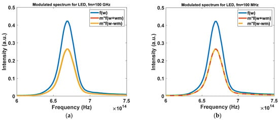
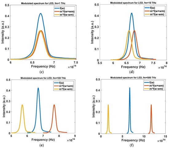
Figure 9.
The spectrum of the modulated input light by LED. (a) Modulated LED light for 100 GHz. (b) Modulated LED light for 100 MHz. (c) Modulated LED light for 1 THz. (d) Modulated LED light for 10 THz. (e) Modulated LED light for 100 THz. (f) Modulated LED light for 500 THz.
The resulted theoretical bandwidth for the passive component is presented in Figure 10. It is clear that the passive structure possesses an ultra-broadband bandwidth in the THz regime. It is worth mentioning that the bandwidth of the structure is significantly greater than the typical LEDs designated for illumination, whose bandwidths are limited to 20 MHz or less [11]. Thus, our antenna will not limit the bandwidth of the VLC systems channel, and any bandwidth restriction will result from the LED or other optical or electrical elements in the communication system. The achievable data rates in a communication system are proportionate to the system’s bandwidth at a particular signal-to-noise ratio. We, therefore, simulated the antenna’s bandwidth, and simultaneously, using the LSC technology, we provided the condition for a high signal-to-noise ratio.
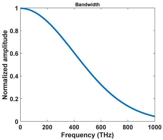
Figure 10.
The total number of photons in the output port of the proposed device versus modulation frequency (total number of photons = summation on photons in the output band).
In this figure, we simulated the effect of the input signal with different frequencies and calculated how many photons come out from the device and in which frequencies. Since the output spectrum is constant and determined by graphene nanoparticles, we calculate the whole photon number in the emission stock shifted band. On the other hand, with a variation of the input modulation frequency, the number of photons in the emission band is changed. Thus, this figure shows in each input modulation frequency how many photons come out in the output stock shifted band. On the other hand, the effect of the input modulation frequency on the performance of the antenna is calculated.
4. Conclusions
In summary, we have demonstrated a new shape of LSCs to verify simple, fast, sensitive, small, and inexpensive optical receiving antennas for VLC systems. The LSC configuration with a PVA host matrix containing QGDs overcomes the etendue limitation, i.e., high concentration gain, a large FOV, and, eventually, a large signal-to-noise ratio are available at the same time. To model the LSC, the Monte-Carlo ray-tracing method was developed, and the results were reported in the form of spectra. Furthermore, the optical efficiency of 1.058% and geometric gain of 44 were obtained. Due to the novel geometry for LSC, since its front surface is considerably larger than its facet edge on which a small photodetector is attached, a significant geometric gain has resulted. The large light-collecting surface and FOV free the LSC from any tracking system and active pointing for VLC. In addition, loss percentages have been calculated in detail and reported. Since the proposed antenna is very small and cost-effective, it becomes a promising candidate for integrating and incorporating mobile devices such as smart mobile phones, computers, tablets, virtual reality headsets, quadcopters, and even clothing that enables rapid mobile communication.
Nevertheless, the performance of the LSC can be improved by increasing the optical efficiency. In future work, we aim to realize better performance for the LSC by utilizing different sizes with different absorption and emission spectra for QGDs instead of single-size QGDs. Further, we will be using white LED with a broad emission spectrum instead of single-color LED, modeling a tandem structure instead of a single layer, and attaching a 99% mirror on the other edges of the LSC.
Author Contributions
S.C. and R.D. provided draft for the paper and simulated the proposed design. A.R. proposed the concept, modeled the structure, edit the paper, and supervised the project. H.M. and P.M. edited the paper and supervised the project. All authors have read and agreed to the published version of the manuscript.
Funding
This research received no external funding.
Institutional Review Board Statement
Not applicable.
Informed Consent Statement
Not applicable.
Data Availability Statement
Not applicable.
Conflicts of Interest
There is no conflict of interest in this work.
Abbreviations
| Abbreviation | Expression |
| VLC | Visible light communication |
| LED | Light-emitting diode |
| FOV | Field of view |
| LSC | Luminescent solar concentrator |
| RF | Radiofrequency |
| EM | Electromagnetic |
| QoS | Quality of service |
| OWC | Optical wireless communication |
| Wi-fi | Wireless fidelity |
| TIR | Total internal reflection |
| QDs | Quantum dots |
| PLQY | Photoluminescence quantum yield |
| QY | Quantum yield |
| GQDs | Graphene quantum dots |
| PVA | Polyvinyl alcohol |
| Probability density function | |
| CDF | Cumulative distribution function |
| NOMA | Non-orthogonal multiple access |
| PDNOMA | Power domain non-orthogonal multiple access |
References
- Yahia, S.; Meraihi, Y.; Ramdane-Cherif, A.; Gabis, A.B.; Acheli, D.; Guan, H. A Survey of Channel Modeling Techniques for Visible Light Communications. J. Netw. Comput. Appl. 2021, 194, 2016–2034. [Google Scholar] [CrossRef]
- Dawy, Z.; Saad, W.; Ghosh, A.; Andrews, J.G.; Yaacoub, E. Toward Massive Machine Type Cellular Communications. IEEE Wirel. Commun. 2017, 24, 120–128. [Google Scholar] [CrossRef]
- Mukherjee, M. Wireless Communication-Moving from RF to Optical; IEEE: Piscataway, NJ, USA, 2016. [Google Scholar]
- Wu, C.; Lai, C.-F. A survey on improving wireless communication with adaptive antenna selection by an intelligent method. Comput. Commun. 2022, 181, 374–403. [Google Scholar] [CrossRef]
- Karunatilaka, D.; Zafar, F.; Kalavally, V.; Parthiban, R. LED Based Indoor Visible Light Communications: State of the Art. IEEE Commun. Surv. Tutor. 2015, 17, 1649–1678. [Google Scholar] [CrossRef]
- Alsulami, O.; Hussein, A.T.; Alresheedi, M.T.; Elmirghani, J.M. Optical wireless communication systems, a survey. arXiv 2018, arXiv:1812.11544. [Google Scholar]
- Dong, Y.; Shi, M.; Yang, X.; Zeng, P.; Gong, J.; Zheng, S.; Zhang, M.; Liang, R.; Ou, Q.; Chi, N.; et al. Nanopatterned luminescent concentrators for visible light communications. Opt. Express 2017, 25, 21926–21934. [Google Scholar] [CrossRef] [PubMed]
- Jenila, C.; Jeyachitra, R.K. Green indoor optical wireless communication systems: Pathway towards pervasive deployment. Digit. Commun. Netw. 2021, 7, 410–444. [Google Scholar] [CrossRef]
- Riaz, A.; Faulkner, G.; Collins, S. A fluorescent antenna for white light visible light communications. In Proceedings of the 2019 Global LIFI Congress (GLC), Paris, France, 12–13 June 2019; pp. 1–4. [Google Scholar]
- Alizadeh Jarchlo, E.; Eso, E.; Doroud, H.; Siessegger, B.; Ghassemlooy, Z.; Caire, G.; Dressler, F. Li-Wi: An upper layer hybrid VLC-WiFi network handover solution. Ad. Hoc. Netw. 2022, 124, 1–13. [Google Scholar] [CrossRef]
- Manousiadis, P.P.; Rajbhandari, S.; Mulyawan, R.; Vithanage, D.A.; Chun, H.; Faulkner, G.; O’Brien, D.C.; Turnbull, G.A.; Collins, S.; Samuel, I.D.W. Wide field-of-view fluorescent antenna for visible light communications beyond the étendue limit. Optica 2016, 3, 702–706. [Google Scholar] [CrossRef]
- Raad Saadallah, N.; Mehedi Fathi, M.; Arwa, R. The efficiency of Li-Fi (Light–Fidelity) security and data transmission compared to Wi-Fi. Mater. Today Proc. 2021, 1–9. [Google Scholar] [CrossRef]
- Ergul, O.; Dinc, E.; Akan, O.B. Communicate to illuminate: State-of-the-art and research challenges for visible light communications. Phys. Commun. 2015, 17, 72–85. [Google Scholar] [CrossRef] [Green Version]
- Hosseinzadeh, A.; Zhou, J.L.; Li, X.; Afsari, M.; Altaee, A. Techno-economic and environmental impact assessment of hydrogen production processes using bio-waste as a renewable energy resource. Renew. Sustain. Energy Rev. 2022, 156, 111991. [Google Scholar] [CrossRef]
- Hosseinzadeh, A.; Zhou, J.L.; Altaee, A.; Li, D. Machine learning modeling and analysis of biohydrogen production from wastewater by the dark fermentation process. Bioresour. Technol. 2022, 343, 126111. [Google Scholar] [CrossRef]
- Hosseinzadeh, A.; Zhou, J.L.; Navidpour, A.H.; Altaee, A. Progress in osmotic membrane bioreactors research: Contaminant removal, microbial community and bioenergy production in wastewater. Bioresour. Technol. 2021, 330, 124998. [Google Scholar] [CrossRef] [PubMed]
- Elamassie, M.; Miramirkhani, F.; Uysal, M. Performance Characterization of Underwater Visible Light Communication. IEEE Trans. Commun. 2019, 67, 543–552. [Google Scholar] [CrossRef]
- Grobe, L.; Paraskevopoulos, A.; Hilt, J.; Schulz, D.; Lassak, F.; Hartlieb, F.; Kottke, C.; Jungnickel, V.; Langer, K. High-speed visible light communication systems. IEEE Commun. Mag. 2013, 51, 60–66. [Google Scholar] [CrossRef]
- Sadat, H.; Abaza, M.; Mansour, A.; Alfalou, A. A Survey of NOMA for VLC Systems: Research Challenges and Future Trends. Sensors 2022, 22, 1395. [Google Scholar] [CrossRef]
- Mounir, M.; El_Mashade, M.B.; Mohamed Aboshosha, A. On The Selection of Power Allocation Strategy in Power Domain Non-Orthogonal Multiple Access (PD-NOMA) for 6G and Beyond. In Transactions on Emerging Telecommunications Technologies; John Wiley & Sons, Inc.: Hoboken, NJ, USA, 2021; p. e4289. [Google Scholar] [CrossRef]
- Aboagye, S.; Ngatched, T.M.N.; Dobre, O.A.; Ndjiongue, A.R. Intelligent Reflecting Surface-Aided Indoor Visible Light Communication Systems. IEEE Commun. Lett. 2021, 25, 3913–3917. [Google Scholar] [CrossRef]
- Gheth, W.; Rabie, K.M.; Adebisi, B.; Ijaz, M.; Harris, G. Performance Analysis of Cooperative and Non-Cooperative Relaying over VLC Channels. Sensors 2020, 20, 3660. [Google Scholar] [CrossRef] [PubMed]
- Peng, X.; Kong, L. Design and optimization of optical receiving antenna based on compound parabolic concentrator for indoor visible light communication. Opt. Commun. 2020, 464, 125447. [Google Scholar] [CrossRef]
- Chun, H.; Rajbhandari, S.; Faulkner, G.; Brien, D.O. Effectiveness of blue-filtering in WLED based indoor Visible light communication. In Proceedings of the 2014 3rd International Workshop in Optical Wireless Communications (IWOW), Funchal, Portugal, 17 September 2014; pp. 60–64. [Google Scholar]
- Portnoi, M.; Haigh, P.A.; Macdonald, T.J.; Ambroz, F.; Parkin, I.P.; Darwazeh, I.; Papakonstantinou, I. Bandwidth limits of luminescent solar concentrators as detectors in free-space optical communication systems. Light Sci. Appl. 2021, 10, 3. [Google Scholar] [CrossRef] [PubMed]
- Papakonstantinou, I.; Tummeltshammer, C. Fundamental limits of concentration in luminescent solar concentrators revised: The effect of reabsorption and nonunity quantum yield. Optica 2015, 2, 841–849. [Google Scholar] [CrossRef]
- Zhao, F.; Cambié, D.; Janse, J.; Wieland, E.W.; Kuijpers, K.P.L.; Hessel, V.; Debije, M.G.; Noël, T. Scale-up of a Luminescent Solar Concentrator-Based Photomicroreactor via Numbering-up. ACS Sustain. Chem. Eng. 2018, 6, 422–429. [Google Scholar] [CrossRef] [PubMed]
- Elbashir, S.; Al-Harbi, F.F.; Elburaih, H.; Al-Faifi, F.; Yahia, I.S. Red photoluminescent PMMA nanohybrid films for modifying the spectral distribution of solar radiation inside greenhouses. Renew. Energy 2016, 85, 928–938. [Google Scholar] [CrossRef]
- Chazot, C.A.C.; Nagelberg, S.; Rowlands, C.J.; Scherer, M.R.J.; Coropceanu, I.; Broderick, K.; Kim, Y.; Bawendi, M.G.; So, P.; Kolle, M. Luminescent Surfaces with Tailored Angular Emission for Compact Dark-Field Imaging Devices. Nat. Photonics 2020, 14, 310–315. [Google Scholar] [CrossRef]
- Bimber, O.; Koppelhuber, A. Toward a Flexible, Scalable, and Transparent Thin-Film Camera. Proc. IEEE 2017, 105, 960–969. [Google Scholar] [CrossRef]
- Shu, J.; Zhang, X.; Wang, P.; Chen, R.; Zhang, H.; Li, D.; Zhang, P.; Xu, J. Monte-Carlo simulations of optical efficiency in luminescent solar concentrators based on all-inorganic perovskite quantum dots. Phys. B Condens. Matter 2018, 548, 53–57. [Google Scholar] [CrossRef]
- Mirzaei, M.R.; Rostami, A.; Matloub, S.; Mirtaghizadeh, H. Ultra-high-efficiency luminescent solar concentrator using superimposed colloidal quantum dots. Opt. Quantum Electron. 2020, 52, 327. [Google Scholar] [CrossRef]
- Khamooshi, M.; Salati, H.; Egelioglu, F.; Hooshyar Faghiri, A.; Tarabishi, J.; Babadi, S. A review of solar photovoltaic concentrators. Int. J. Photoenergy 2014, 2014, 958521. [Google Scholar] [CrossRef]
- Liu, C.; Li, B. Multiple dyes containing luminescent solar concentrators with enhanced absorption and efficiency. J. Opt. 2015, 17, 025901. [Google Scholar] [CrossRef]
- Maggioni, G.; Campagnaro, A.; Carturan, S.; Quaranta, A. Dye-doped parylene-based thin film materials: Application to luminescent solar concentrators. Sol. Energy Mater. Sol. Cells 2013, 108, 27–37. [Google Scholar] [CrossRef]
- Graffion, J.; Cattoën, X.; Wong Chi Man, M.; Fernandes, V.R.; André, P.S.; Ferreira, R.A.S.; Carlos, L.D. Modulating the Photoluminescence of Bridged Silsesquioxanes Incorporating Eu3+-Complexed N,N′-Diureido-2,2′-bipyridine Isomers: Application for Luminescent Solar Concentrators. Chem. Mater. 2011, 23, 4773–4782. [Google Scholar] [CrossRef] [Green Version]
- Nolasco, M.M.; Vaz, P.M.; Freitas, V.T.; Lima, P.P.; André, P.S.; Ferreira, R.A.S.; Vaz, P.D.; Ribeiro-Claro, P.; Carlos, L.D. Engineering highly efficient Eu(iii)-based tri-ureasil hybrids toward luminescent solar concentrators. J. Mater. Chem. A 2013, 1, 7339–7350. [Google Scholar] [CrossRef]
- Nikolaidou, K.; Sarang, S.; Hoffman, C.; Mendewala, B.; Ishihara, H.; Lu, J.Q.; Ilan, B.; Tung, V.; Ghosh, S. Hybrid Perovskite Thin Films as Highly Efficient Luminescent Solar Concentrators. Adv. Opt. Mater. 2016, 4, 2126–2132. [Google Scholar] [CrossRef]
- Zhao, H.; Zhou, Y.; Benetti, D.; Ma, D.; Rosei, F. Perovskite quantum dots integrated into large-area luminescent solar concentrators. Nano Energy 2017, 37, 214–223. [Google Scholar] [CrossRef]
- Li, S.; Liu, H.; Chen, W.; Zhou, Z.; Wu, D.; Lu, R.; Zhao, B.; Hao, J.; Yang, L.; Yang, H.; et al. Low reabsorption and stability enhanced luminescent solar concentrators based on silica encapsulated quantum rods. Sol. Energy Mater. Sol. Cells 2020, 206, 110321. [Google Scholar] [CrossRef]
- Zhao, H.; Benetti, D.; Jin, L.; Zhou, Y.; Rosei, F.; Vomiero, A. Absorption Enhancement in “Giant” Core/Alloyed-Shell Quantum Dots for Luminescent Solar Concentrator. Small 2016, 12, 5354–5365. [Google Scholar] [CrossRef]
- Currie Michael, J.; Mapel Jonathan, K.; Heidel Timothy, D.; Goffri, S.; Baldo Marc, A. High-Efficiency Organic Solar Concentrators for Photovoltaics. Science 2008, 321, 226–228. [Google Scholar] [CrossRef]
- Zhou, Y.; Benetti, D.; Tong, X.; Jin, L.; Wang, Z.M.; Ma, D.; Zhao, H.; Rosei, F. Colloidal carbon dots based highly stable luminescent solar concentrators. Nano Energy 2018, 44, 378–387. [Google Scholar] [CrossRef]
- Zhao, H.; Benetti, D.; Tong, X.; Zhang, H.; Zhou, Y.; Liu, G.; Ma, D.; Sun, S.; Wang, Z.M.; Wang, Y.; et al. Efficient and stable tandem luminescent solar concentrators based on carbon dots and perovskite quantum dots. Nano Energy 2018, 50, 756–765. [Google Scholar] [CrossRef]
- Peyronel, T.; Quirk, K.; Wang, S.; Tiecke, T. Luminescent detector for free-space-optical communication. Optica 2016, 3, 787–792. [Google Scholar] [CrossRef]
- Şahin Biryol, D.; Ilan, B.; Kelley, D. Monte-Carlo simulations of light propagation in luminescent solar concentrators based on semiconductor nanoparticles. J. Appl. Phys. 2011, 110, 033108. [Google Scholar] [CrossRef] [Green Version]
- Slooff, L.H.; Bende, E.E.; Burgers, A.R.; Budel, T.; Pravettoni, M.; Kenny, R.P.; Dunlop, E.D.; Büchtemann, A. A luminescent solar concentrator with 7.1% power conversion efficiency. Phys. Status Solidi (RRL)—Rapid Res. Lett. 2008, 2, 257–259. [Google Scholar] [CrossRef] [Green Version]
- Gupta, P.; Pandey, A.; Vairagi, K.; Mondal, S.K. Solving Fresnel equation for refractive index using reflected optical power obtained from Bessel beam interferometry. Rev. Sci. Instrum. 2019, 90, 015110. [Google Scholar] [CrossRef] [PubMed]
- El-Badry, Y.A.; Mahmoud, K.H. Optical study of a static benzoxazine derivative doped poly (vinyl) pyrrolidone—Poly(vinyl) alcohol blend system. Spectrochim. Acta Part A Mol. Biomol. Spectrosc. 2019, 219, 307–312. [Google Scholar] [CrossRef] [PubMed]
- Rastkar Mirzaei, M.; Rostami, A.; Matloub, S.; Nazari, M. Design and optimization of graphene quantum dot-based luminescent solar concentrator using Monte-Carlo simulation. Energy Built Environ. 2021. [Google Scholar] [CrossRef]
- Brouwer, A.M. Standards for photoluminescence quantum yield measurements in solution (IUPAC Technical Report). Pure Appl. Chem. 2011, 83, 2213–2228. [Google Scholar] [CrossRef] [Green Version]
- Li, M.-L.; Kuo, Y.-C.; Yeh, C.-K. Amplitude-Modulation Chirp Imaging for Contrast Detection. Ultrasound Med. Biol. 2010, 36, 1535–1545. [Google Scholar] [CrossRef]
Publisher’s Note: MDPI stays neutral with regard to jurisdictional claims in published maps and institutional affiliations. |
© 2022 by the authors. Licensee MDPI, Basel, Switzerland. This article is an open access article distributed under the terms and conditions of the Creative Commons Attribution (CC BY) license (https://creativecommons.org/licenses/by/4.0/).