Large Mode Area Single Mode Fiber with a Twisted Polygon-Shaped Core


Abstract
:1. Introduction
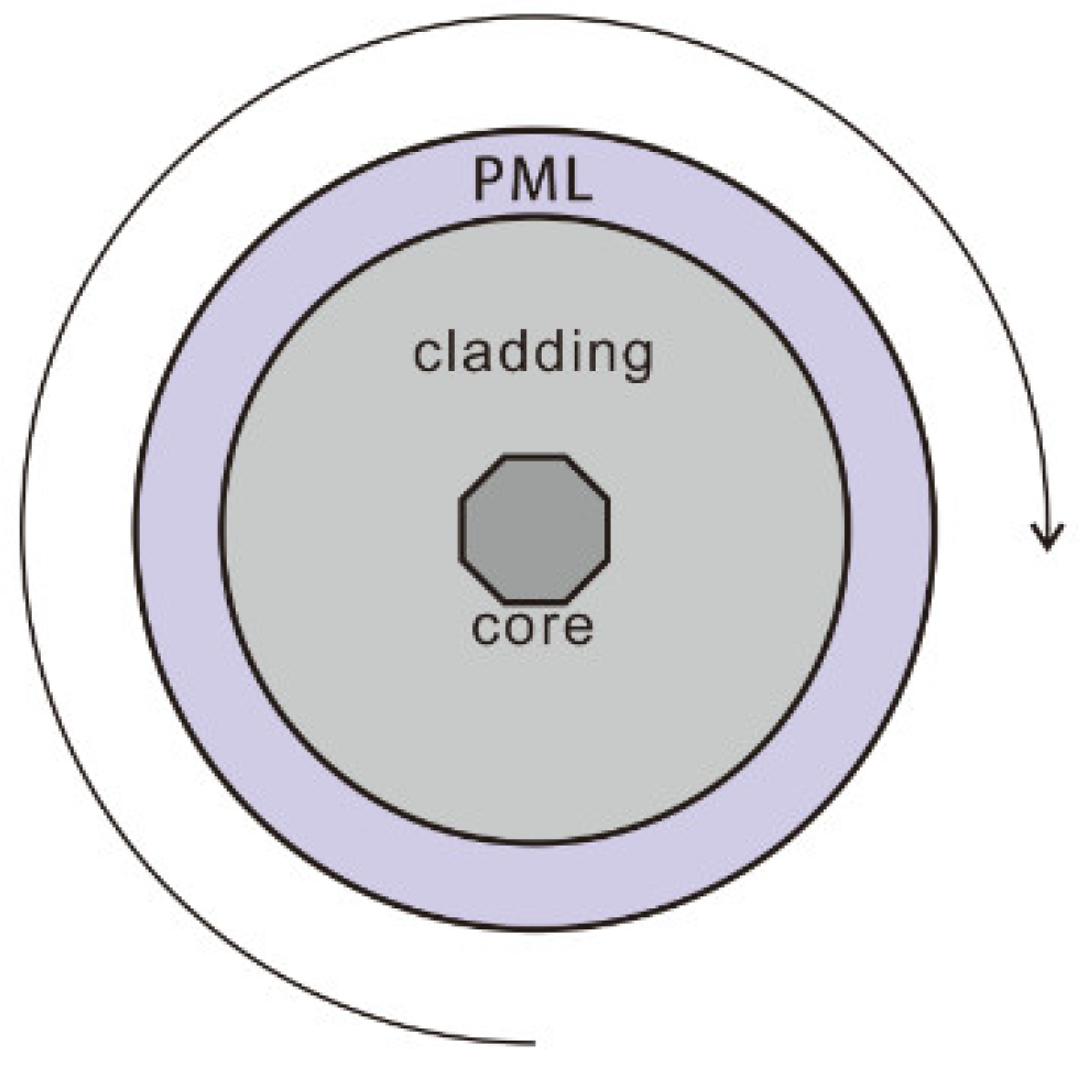
2. Modeling Method
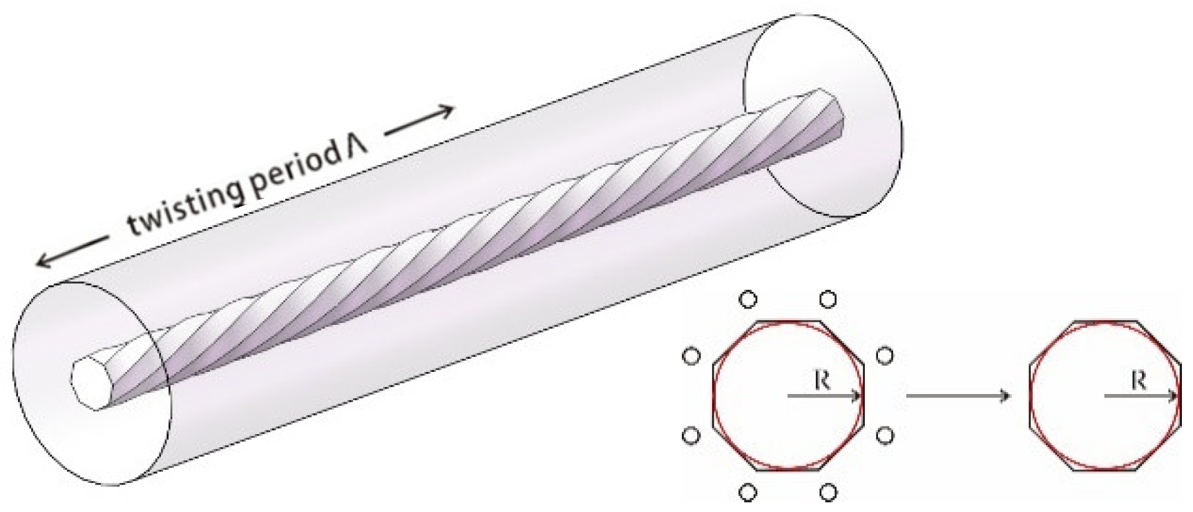
3. Twisted Polygon-Shaped Core Fibers
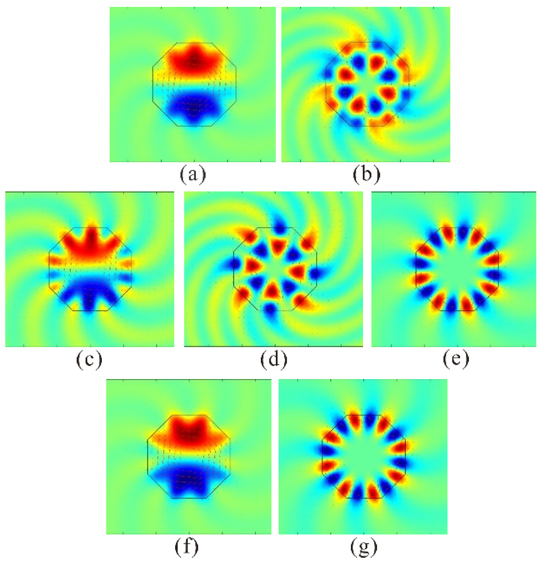
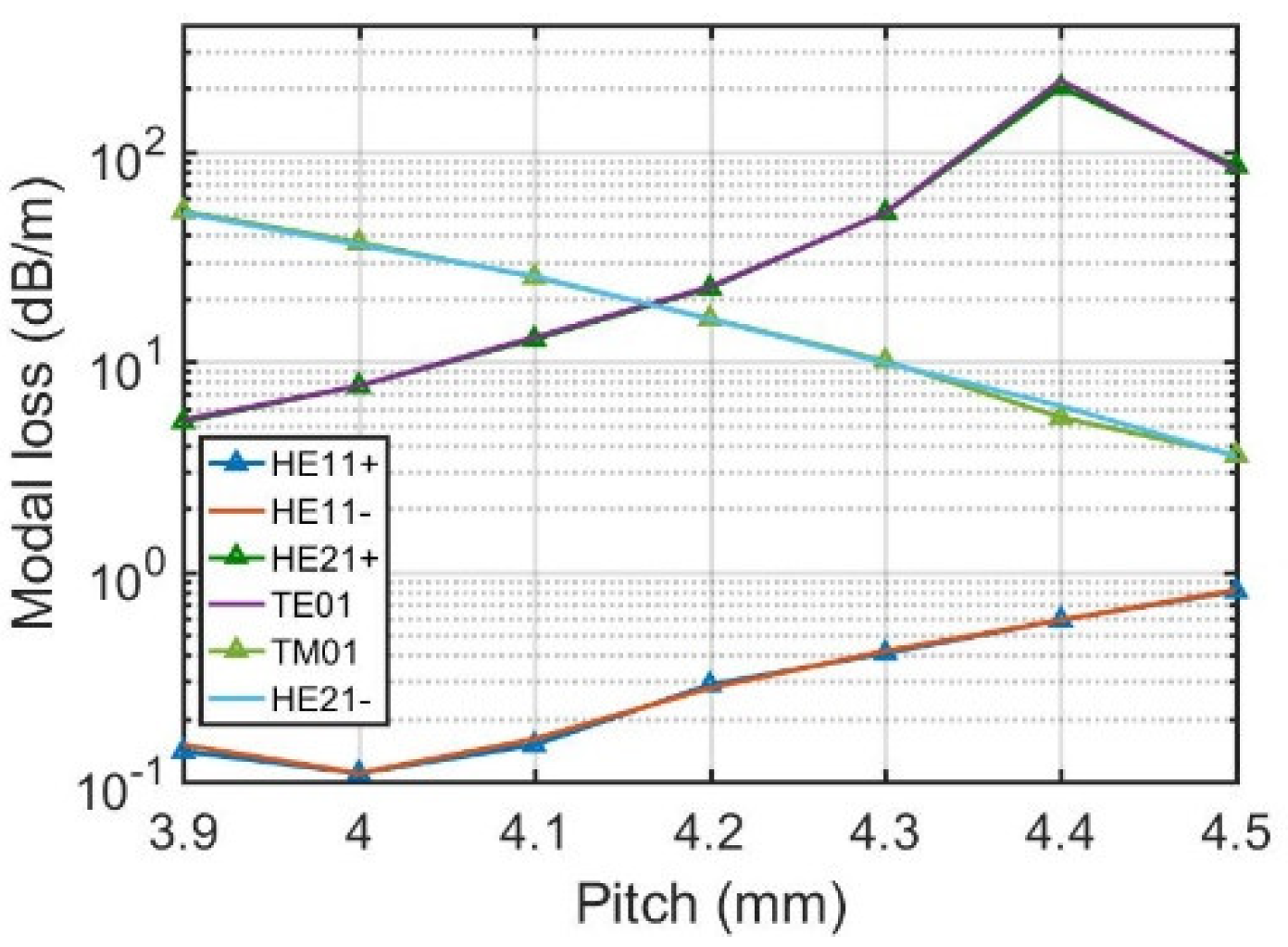
3.1. Twisted Octagon-Shaped Core Fiber
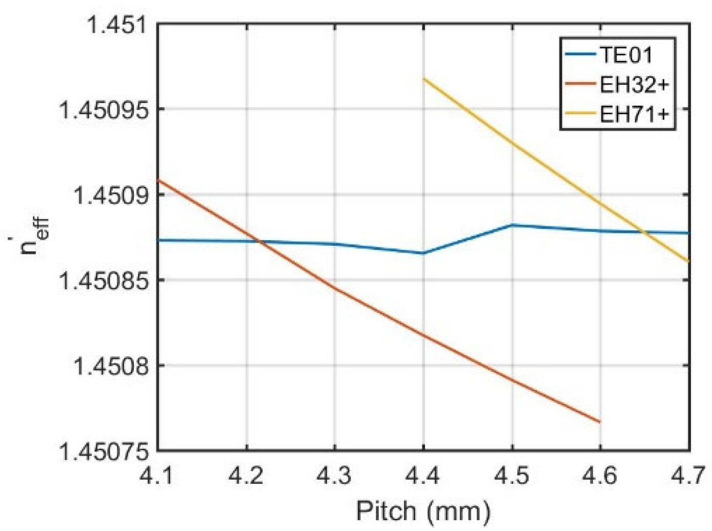
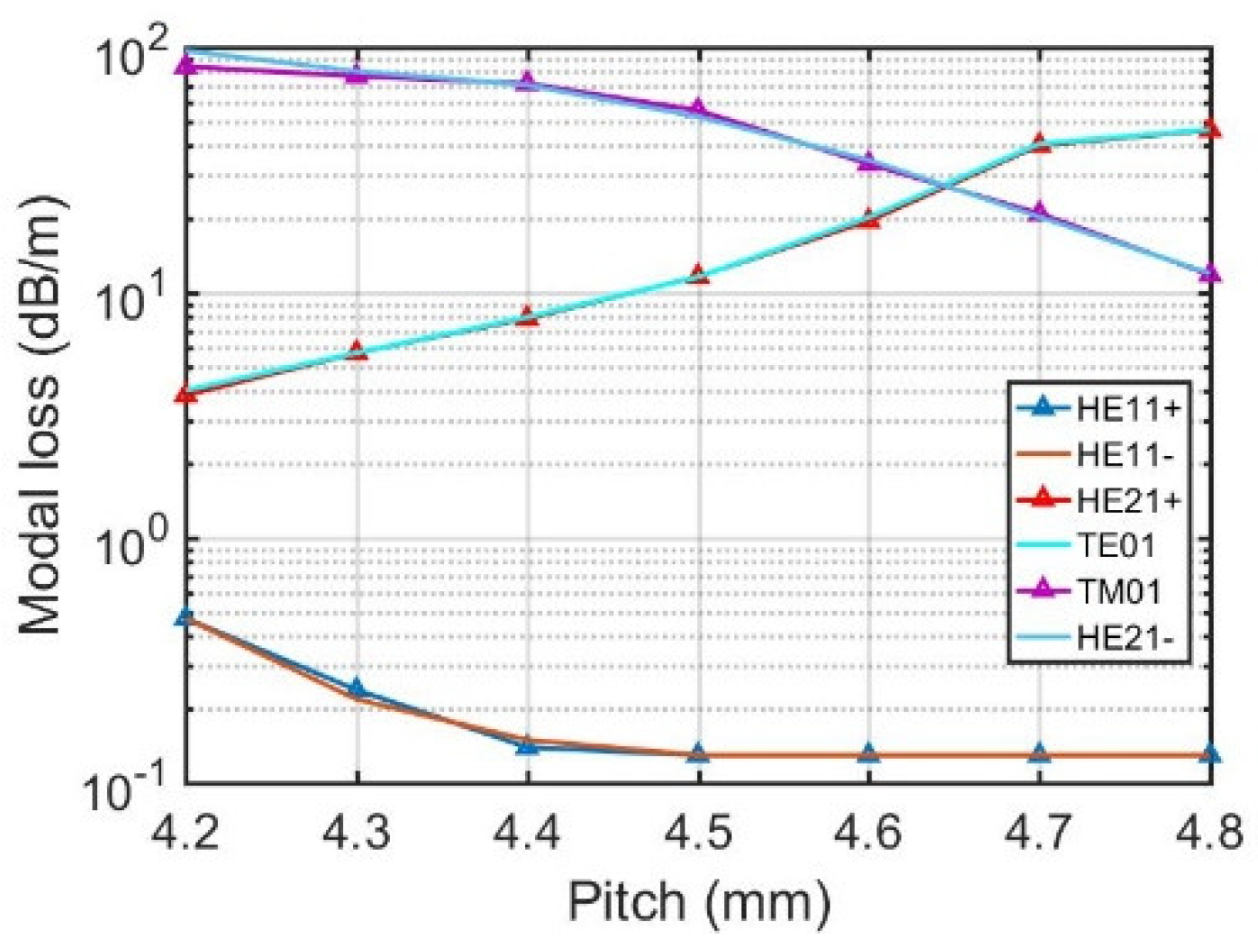
3.2. Twisted Heptagon-Shaped Core Fiber
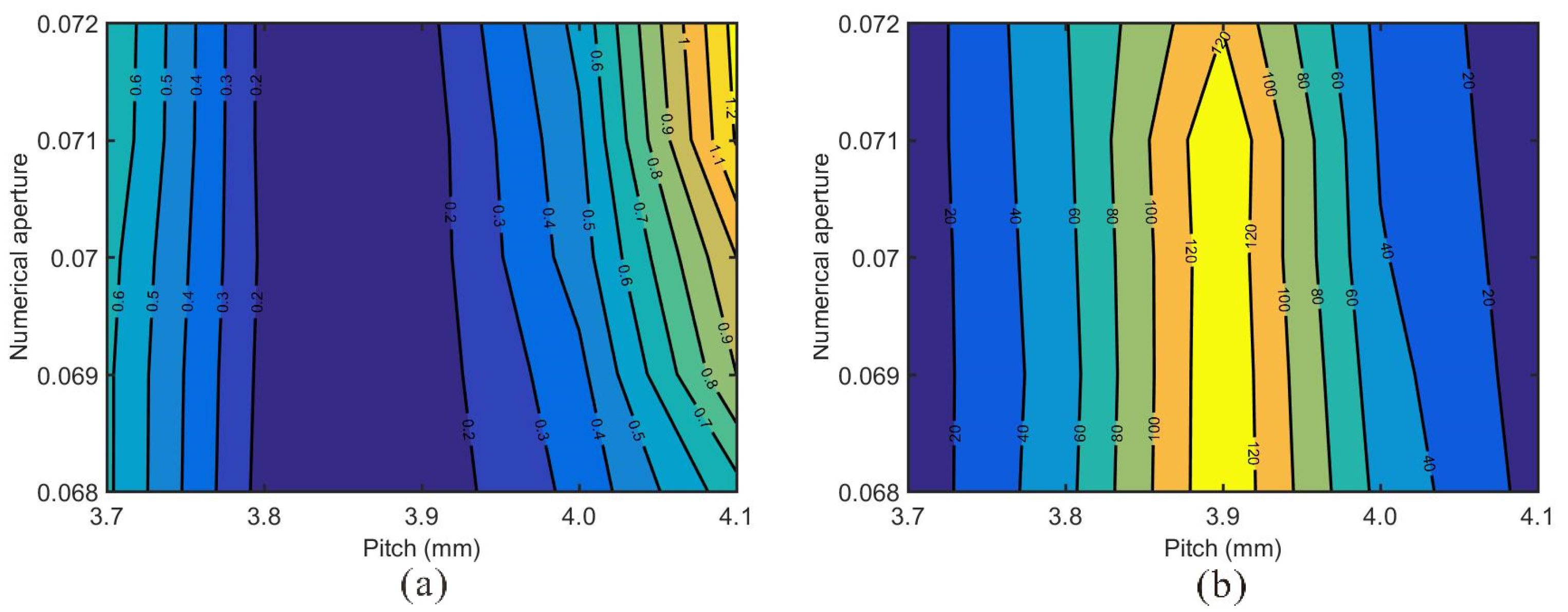
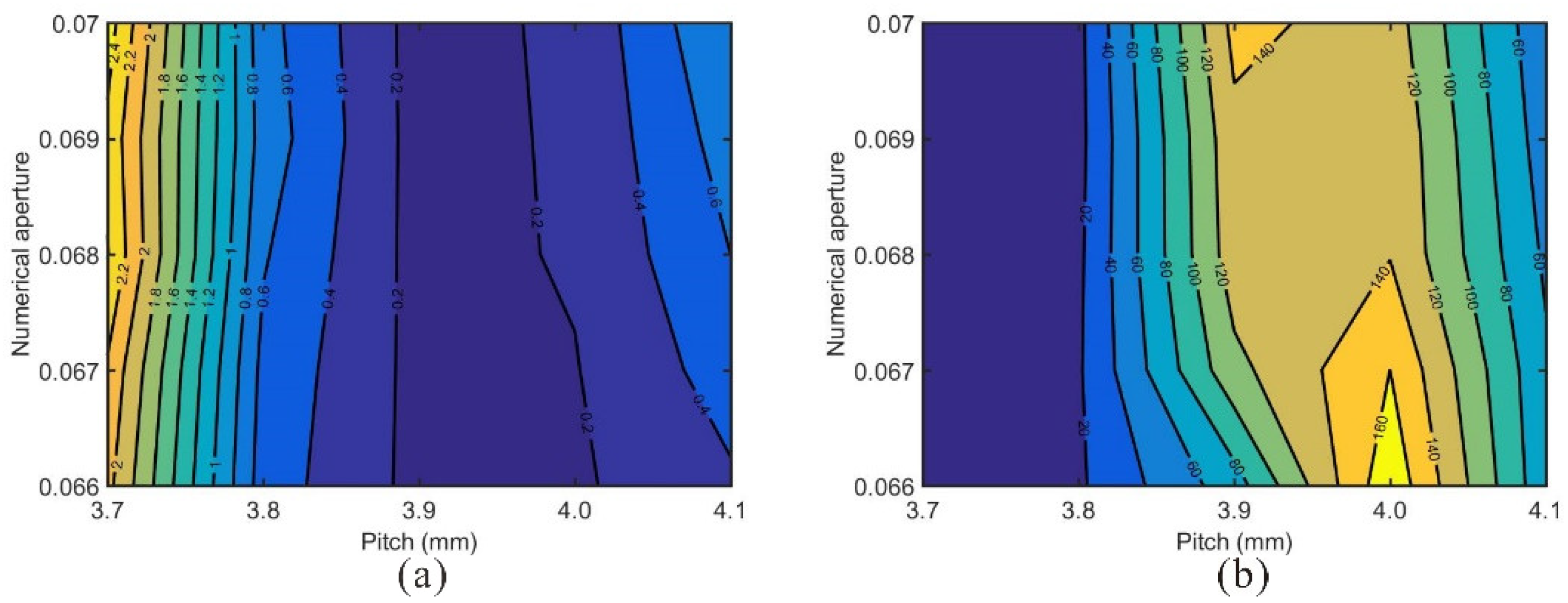
3.3. Mode Area Scaling
3.4. Discussion
4. Conclusions
Author Contributions
Funding
Data Availability Statement
Conflicts of Interest
References
- Dawson, J.W.; Messerly, M.J.; Beach, R.J.; Shverdin, M.Y.; Stappaerts, A.; Sridharan, A.K.; Pax, P.H.; Heebner, J.E.; Siders, C.W.; Barty, C.P.J. Analysis of the Scalability of Diffraction-Limited Fiber Lasers and Amplifiers to High Average Power. Opt. Express 2008, 16, 13240–13266. [Google Scholar] [CrossRef] [PubMed]
- Shi, W.; Fang, Q.; Zhu, X.; Norwood, R.A.; Peyghambarian, N. Fiber Lasers and Their Applications [Invited]. Appl. Opt. 2014, 53, 6554–6568. [Google Scholar] [CrossRef] [PubMed]
- Gapontsev, V.; Avdokhin, A.; Kadwani, P.; Samartsev, I.; Platonov, N.; Yagodkin, R. SM Green Fiber Laser Operating in CW and QCW Regimes and Producing over 550W of Average Output Power. In Nonlinear Frequency Generation and Conversion: Materials, Devices, and Applications XIII; SPIE: Bellingham, WA, USA, 2014; Volume 8964, pp. 36–44. [Google Scholar]
- Liu, Z.; Ma, P.; Su, R.; Tao, R.; Ma, Y.; Wang, X.; Zhou, P. High-Power Coherent Beam Polarization Combination of Fiber Lasers: Progress and Prospect [Invited]. J. Opt. Soc. Am. B 2017, 34, A7–A14. [Google Scholar] [CrossRef]
- Buikema, A.; Jose, F.; Augst, S.J.; Fritschel, P.; Mavalvala, N. Narrow-Linewidth Fiber Amplifier for Gravitational-Wave Detectors. Opt. Lett. 2019, 44, 3833–3836. [Google Scholar] [CrossRef] [PubMed]
- Li, M.J.; Chen, X.; Liu, A.; Gray, S.; Wang, J.; Walton, D.T.; Zenteno, L.A. Limit of Effective Area for Single-Mode Operation in Step-Index Large Mode Area Laser Fibers. J. Lightwave Technol. 2009, 27, 3010–3016. [Google Scholar]
- Jain, D.; Jung, Y.; Barua, P.; Alam, S.; Sahu, J.K. Demonstration of Ultra-Low NA Rare-Earth Doped Step Index Fiber for Applications in High Power Fiber Lasers. Opt. Express 2015, 23, 7407–7415. [Google Scholar] [CrossRef] [PubMed] [Green Version]
- Franczyk, M.; Stawicki, K.; Lisowska, J.; Michalik, D.; Filipkowski, A.; Buczynski, R. Numerical Studies on Large-Mode Area Fibers with Nanostructured Core for Fiber Lasers. J. Lightwave Technol. 2018, 36, 5334–5343. [Google Scholar] [CrossRef]
- Franczyk, M.; Pysz, D.; Pucko, P.; Michalik, D.; Biduś, M.; Dłubek, M.; Buczyński, R. Yb3+ Doped Silica Nanostructured Core Fiber Laser. Opt. Express 2019, 27, 35108–35119. [Google Scholar] [CrossRef]
- Limpert, J.; Liem, A.; Reich, M.; Schreiber, T.; Nolte, S.; Zellmer, H.; Tünnermann, A.; Broeng, J.; Petersson, A.; Jakobsen, C. Low-Nonlinearity Single-Transverse-Mode Ytterbium-Doped Photonic Crystal Fiber Amplifier. Opt. Express 2004, 12, 1313–1319. [Google Scholar] [CrossRef]
- Huang, L.; Kong, L.; Leng, J.; Zhou, P.; Guo, S.; Cheng, X. Impact of High-Order-Mode Loss on High-Power Fiber Amplifiers. J. Opt. Soc. Am. B 2016, 33, 1030–1037. [Google Scholar] [CrossRef]
- Koplow, J.P.; Kliner, D.A.V.; Goldberg, L. Single-Mode Operation of a Coiled Multimode Fiber Amplifier. Opt. Lett. 2000, 25, 442–444. [Google Scholar] [CrossRef] [PubMed] [Green Version]
- Jain, D.; Jung, Y.; Nunez-Velazquez, M.; Sahu, J.K. Extending Single Mode Performance of All-Solid Large-Mode-Area Single Trench Fiber. Opt. Express 2014, 22, 31078–31091. [Google Scholar] [CrossRef] [PubMed] [Green Version]
- Jain, D.; Baskiotis, C.; Sahu, J.K. Mode Area Scaling with Multi-Trench Rod-Type Fibers. Opt. Express 2013, 21, 1448–1455. [Google Scholar] [CrossRef] [PubMed]
- Jain, D.; Alam, S.; Codemard, C.; Jung, Y.; Zervas, M.N.; Sahu, J.K. High Power, Compact, Picosecond MOPA Based on Single Trench Fiber with Single Polarized Diffraction-Limited Output. Opt. Lett. 2015, 40, 4150–4153. [Google Scholar] [CrossRef] [PubMed]
- Kashiwagi, M.; Saitoh, K.; Takenaga, K.; Tanigawa, S.; Matsuo, S.; Fujimaki, M. Effectively Single-Mode All-Solid Photonic Bandgap Fiber with Large Effective Area and Low Bending Loss for Compact High-Power All-Fiber Lasers. Opt. Express 2012, 20, 15061–15070. [Google Scholar] [CrossRef]
- Fermann, M.E. Single-Mode Excitation of Multimode Fibers with Ultrashort Pulses. Opt. Lett. 1998, 23, 52–54. [Google Scholar] [CrossRef] [PubMed]
- Nicholson, J.W.; DeSantolo, A.; Westbrook, P.S.; Windeler, R.S.; Kremp, T.; Headley, C.; DiGiovanni, D.J. Axicons for Mode Conversion in High Peak Power, Higher-Order Mode, Fiber Amplifiers. Opt. Express 2015, 23, 33849–33860. [Google Scholar] [CrossRef]
- Wang, X.; Chen, Y.; Hageman, W.; Kim, G.U.; Richardson, M.; Xiong, C.; Ballato, J.; Bass, M. Transverse Mode Competition in Gain-Guided Index Antiguided Fiber Lasers. J. Opt. Soc. Am. B 2012, 29, 191–196. [Google Scholar] [CrossRef]
- Edavalath, N.N.; Günendi, M.C.; Beravat, R.; Wong, G.K.L.; Frosz, M.H.; Ménard, J.-M.; Russell, P.S.J. Higher-Order Mode Suppression in Twisted Single-Ring Hollow-Core Photonic Crystal Fibers. Opt. Lett. 2017, 42, 2074–2077. [Google Scholar] [CrossRef]
- Ma, X.; Liu, C.; Chang, G.; Galvanauskas, A. Angular-Momentum Coupled Optical Waves in Chirally-Coupled-Core Fibers. Opt. Express 2011, 19, 2252–2258. [Google Scholar] [CrossRef]
- Ma, X.; Zhu, C.; Hu, I.-N.; Kaplan, A.; Galvanauskas, A. Single-Mode Chirally-Coupled-Core Fibers with Larger than 50µm Diameter Cores. Opt. Express 2014, 22, 9206–9219. [Google Scholar] [CrossRef] [PubMed]
- Napiorkowski, M.; Urbanczyk, W. Rigorous Simulations of Coupling between Core and Cladding Modes in a Double-Helix Fiber. Opt. Lett. 2015, 40, 3324–3327. [Google Scholar] [CrossRef] [PubMed]
- Shen, X.; Yang, Z.; Xi, X.; Zhang, Z.; Wei, W. Numerical Investigation for the Mode Transmission Characteristics of a Large Mode Area Optical Fiber with Heterogeneous Helical Claddings Designed for 2.0μm. Opt. Lett. 2021, 46, 4342–4345. [Google Scholar] [CrossRef] [PubMed]
- Napiorkowski, M.; Urbanczyk, W. Rigorous Modeling of Twisted Anisotropic Optical Fibers with Transformation Optics Formalism. Opt. Express 2021, 29, 15199–15216. [Google Scholar] [CrossRef] [PubMed]
- Napiorkowski, M.; Urbanczyk, W. Role of Symmetry in Mode Coupling in Twisted Microstructured Optical Fibers. Opt. Lett. 2018, 43, 395–398. [Google Scholar] [CrossRef]
- Nicolet, A.; Zolla, F.; Guenneau, S. Modelling of twisted optical waveguides with edge elements. Eur. Phys. J. Appl. Phys. 2004, 28, 153–157. [Google Scholar] [CrossRef]
- Napiorkowski, M.; Urbanczyk, W. Rigorous Simulations of a Helical Core Fiber by the Use of Transformation Optics Formalism. Opt. Express 2014, 22, 23108–23120. [Google Scholar] [CrossRef]
- Han, J.; Liu, E.; Liu, J. Circular gradient-diameter photonic crystal fiber with large mode area and low bending loss. J. Opt. Soc. Am. A 2019, 36, 533–539. [Google Scholar] [CrossRef]
- Wang, Y.; Liao, L.; Zhao, N.; Dai, N.; Li, H.; Peng, J.; Li, J. A New Type of Yb3+ Doped Fiber with an Octagonal-Shaped Core. In Proceedings of the 2015 Conference on Lasers and Electro-Optics (CLEO), San Jose, CA, USA, 10–15 August 2015. [Google Scholar]


| LP Modes | Modes in Helicoidal Coordinates | Azimuthal Mode Number | Effective RI (Untwisted→Twisted) | Modal Loss in dB/m |
|---|---|---|---|---|
| LP01 | HE11+ | 1 | 1.450985→1.451238−5.605259e−9i | 0.29 |
| HE11− | 1 | 1.450985→1.450731−5.413734e−9i | 0.28 | |
| LP11 | HE21+ | 2 | 1.450875→1.451379−4.381172e−7i | 22.47 |
| TE01 | 0 | 1.450875→1.450872−4.441430e−7i | 22.77 | |
| TM01 | 0 | 1.450875→1.450875−3.133396e−7i | 16.05 | |
| HE21− | 2 | 1.450875→1.450369−3.110502e−7i | 15.95 |
| LP Modes | Modes in Helicoidal Coordinates | Azimuthal Mode Number | Effective RI (Untwisted→Twisted) | Modal Loss in dB/m |
|---|---|---|---|---|
| LP01 | HE11+ | 1 | 1.450898→1.451134−2.510708e−9i | 0.13 |
| HE11− | 1 | 1.450898→1.450661−2.462778e−9i | 0.13 | |
| LP11 | HE21+ | 2 | 1.450790→1.451259−2.266232e−7i | 11.64 |
| TE01 | 0 | 1.450790→1.450786−2.256496e−7i | 11.59 | |
| TM01 | 0 | 1.450790→1.450791−1.083072e−6i | 55.40 | |
| HE21− | 2 | 1.450790→1.450318−1.022606e−6i | 52.32 |
Publisher’s Note: MDPI stays neutral with regard to jurisdictional claims in published maps and institutional affiliations. |
© 2022 by the authors. Licensee MDPI, Basel, Switzerland. This article is an open access article distributed under the terms and conditions of the Creative Commons Attribution (CC BY) license (https://creativecommons.org/licenses/by/4.0/).
Share and Cite
Sun, K.; Zhu, S.; Li, L.; Hu, C.; Ma, X. Large Mode Area Single Mode Fiber with a Twisted Polygon-Shaped Core. Photonics 2022, 9, 221. https://doi.org/10.3390/photonics9040221
Sun K, Zhu S, Li L, Hu C, Ma X. Large Mode Area Single Mode Fiber with a Twisted Polygon-Shaped Core. Photonics. 2022; 9(4):221. https://doi.org/10.3390/photonics9040221
Chicago/Turabian StyleSun, Kexiong, Shicheng Zhu, Li Li, Chang Hu, and Xiuquan Ma. 2022. "Large Mode Area Single Mode Fiber with a Twisted Polygon-Shaped Core" Photonics 9, no. 4: 221. https://doi.org/10.3390/photonics9040221
APA StyleSun, K., Zhu, S., Li, L., Hu, C., & Ma, X. (2022). Large Mode Area Single Mode Fiber with a Twisted Polygon-Shaped Core. Photonics, 9(4), 221. https://doi.org/10.3390/photonics9040221