1. Introduction
Growing demands for high data rates and low latency communication systems, particularly in indoor and in-building environments, contribute to the significant consideration of the usage of 60 GHz and above unlicensed frequency bands in the United States [
1]. Recently, optical spectrum research focused on indoor wireless communication [
2]. Significant interests of Terahertz (THz) or above level communications on 6G development show the possible opportunities of the optical spectrum in the perspectives of wireless networks, interactive communications, mobility service, internet of things, and even bio-tissues [
3]. Especially in the case of mobility service for in-building, its communication systems have to consider VLC for high data rates instead of current wireless systems such as NB-IoT or LoRaWAN [
4].
Since the optical spectrum is in the frequency range of at least 300 GHz, multicarrier OFDM modulation can be the possible candidate for the robust modulation scheme in that spectrum for indoor visible light communications [
5]. OFDM has the advantages of a high data rate and bandwidth efficiency. It also provides a scheme to mitigate intersymbol interference caused by multipath propagation. However, in VLC, the LEDs’ nonlinear behavior can severely affect OFDM’s performance due to its high Peak-to-Average Power Ratio.
For LEDs, the power amplifier operates up to the saturation for maximum power, and it may cause unwanted nonlinear distortion in amplitude and phase in this power operation. Signal clipping issue in the amplifier is another critical matter for OFDM [
6]. The back-off to the average input power ensures that the amplifier avoids saturation, but the problem still exists that the back-off may deteriorate power efficiency. Linearization through predistortion is another method to compensate for the PA nonlinear distortion.
Since the LED is the primary source of nonlinearity, the baseband OFDM signal in VLC systems is modulated with the instantaneous power on the optical carrier called intensity modulation. Asymmetrically Clipped Optical OFDM (ACO-OFDM) and DCO-OFDM are two primary forms of OFDM with intensity modulation. In order to produce a positive signal, the bipolar OFDM signal in DCO-OFDM is superimposed on a bias point. On the other hand, the OFDM signal in ACO-OFDM is unipolar modulated by only the odd sub-carriers, and the unipolar modulation suppresses the signal at zero levels [
7]. In this paper, we select DCO-OFDM for spectral efficiency.
For the investigation of the nonlinear distortion, various bias points are considered. A power back-off scheme is a possible option for the OFDM signal to set the distortion levels with LED operation near the bias point in a quasilinear segment of the LED characteristic. After sampling the LED transfer function, the predistortion method consists of the table format of the inverse of the characteristic function and compensates for the LED nonlinearity [
8]. However, this method has data measurement issues in that the system must directly identify the LED data characterization. An adaptive normalized least mean square (NLMS) algorithm can be another technique to estimate correct LED bias data [
9]. To compensate for the nonlinearity, it directly predicts the distortion levels given the environmental changes instead of using the fixed values of the existing Memory Look-Up-Table. High complexity in the algorithm becomes one of the remaining issues in practicality. In other words, a simple predistortion approach is necessary to resolve the distortion matters with preserving practical usability.
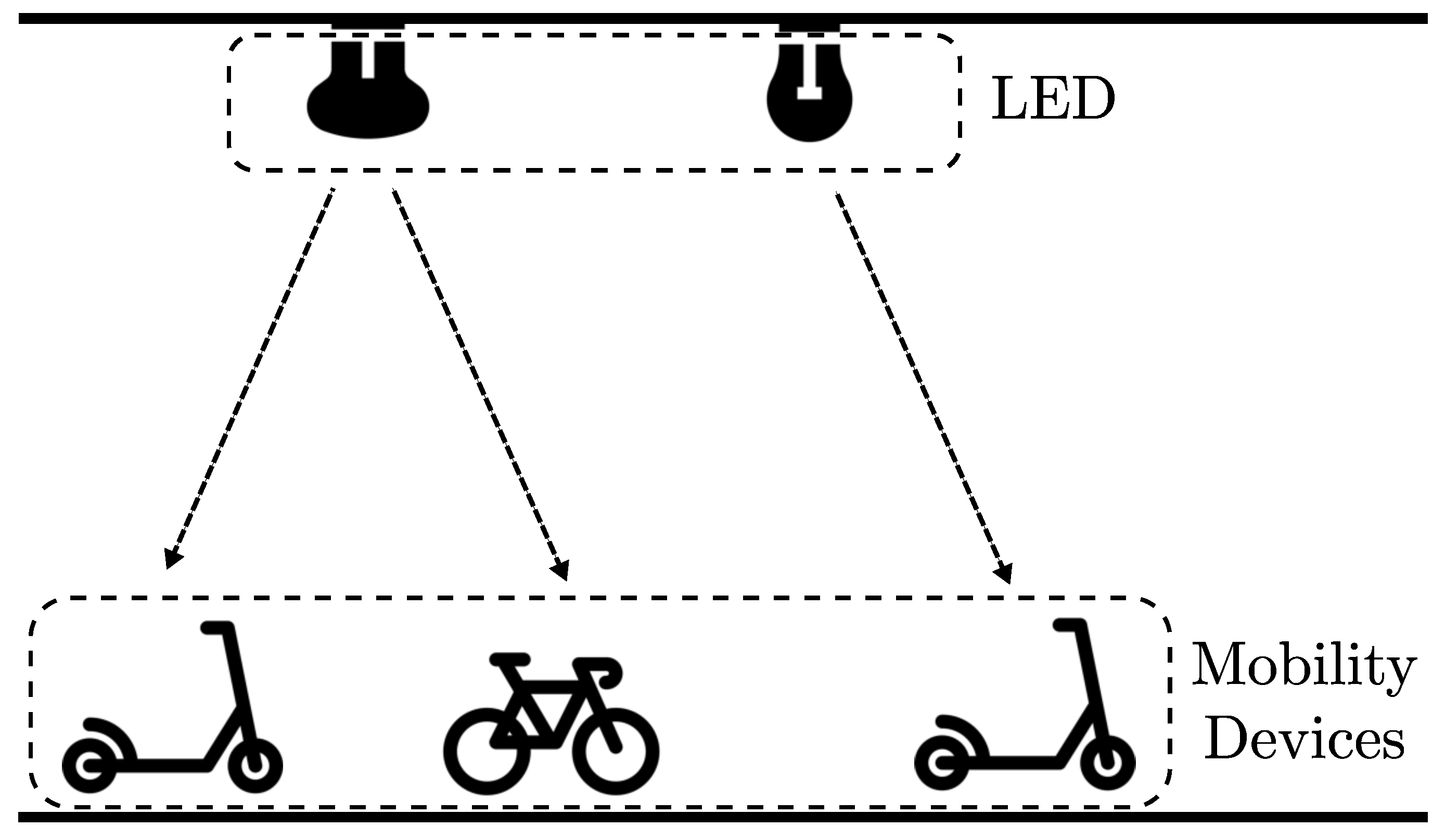
Especially in the case of mobility services, indoor mobility transportation becomes a possible scenario due to the LED light in the building. As shown in
Figure 1, using LED lights in the hallway, the building or infrastructure can broadcast the information and data specifically designed for mobility services, indoor navigation maps, announcements, and over-the-air updates. In that communication system scene, the mobility devices such as scooters, bicycles, or autonomous robots are in a nonstationary position, and their channels have a line of sight with a few reflections, which means the channel condition is the Rician fading. In addition, those mobile devices are battery-critical, and energy efficiency is one of their top priorities. In other words, the VLC communication systems in this mobility service have to consider dynamic environmental conditions and effectiveness to combat LED distortion.
In this paper, we propose two approaches: (1) the predistortion method, effectively using the coefficient approximation without sampling the LED transfer function, and (2) the Bidirectional LSTM Approach to training the LED distortion correction without knowing the LED modeling. When we compare the BER performances of these two approaches to the case without compensation, the result confirms the possible improvement of LED distortion in the VLC OFDM system.
This paper is organized as follows.
Section 2 illustrates the development procedure of the LED model and distortion.
Section 3 and
Section 4 introduce the OFDM model, initial predistortion modeling, and the coefficient approximation scheme for LED distortion correction.
Section 5 discusses the possible deep learning application for this VLC system to implement predistortion.
Section 6 compares system performances of 16 Quadrature Amplitude Modulation (QAM) and 64 QAM in predistortion modeling and deep learning schemes. After presenting performance results, we conclude our paper in
Section 7.
2. Nonlinear Characteristics of Different LEDs in the VLC System
In the ideal condition, we consider an ideal LED as a distortion-free diode. We also define the input port signal as the driving current and the output port signal power as the emitted optical power. LEDs also exhibit nonlinearities, introducing distortions on the emitted signal [
10]. Since the physical models, which include the dynamic rate equation model [
10], failed to approximate practical LEDs, we model the static transfer function of the LED output power,
, with polynomials shown in Equation (
1).
where
is the driving current,
is the bias current, and
is the
n-th order power coefficient of the transfer function. Although polynomial orders are required to be
to realistically model transfer functions, a second-order polynomial is proven to be a fair description [
11]. The polynomial function in question is
In this paper, we set the normalized current , and , , and are the Direct Current (DC) constant, the linear coefficient, and the second-order nonlinearity coefficient. Moreover, it is also known that an LED has constant behavior. As a result, the derivation of with respect to must be .
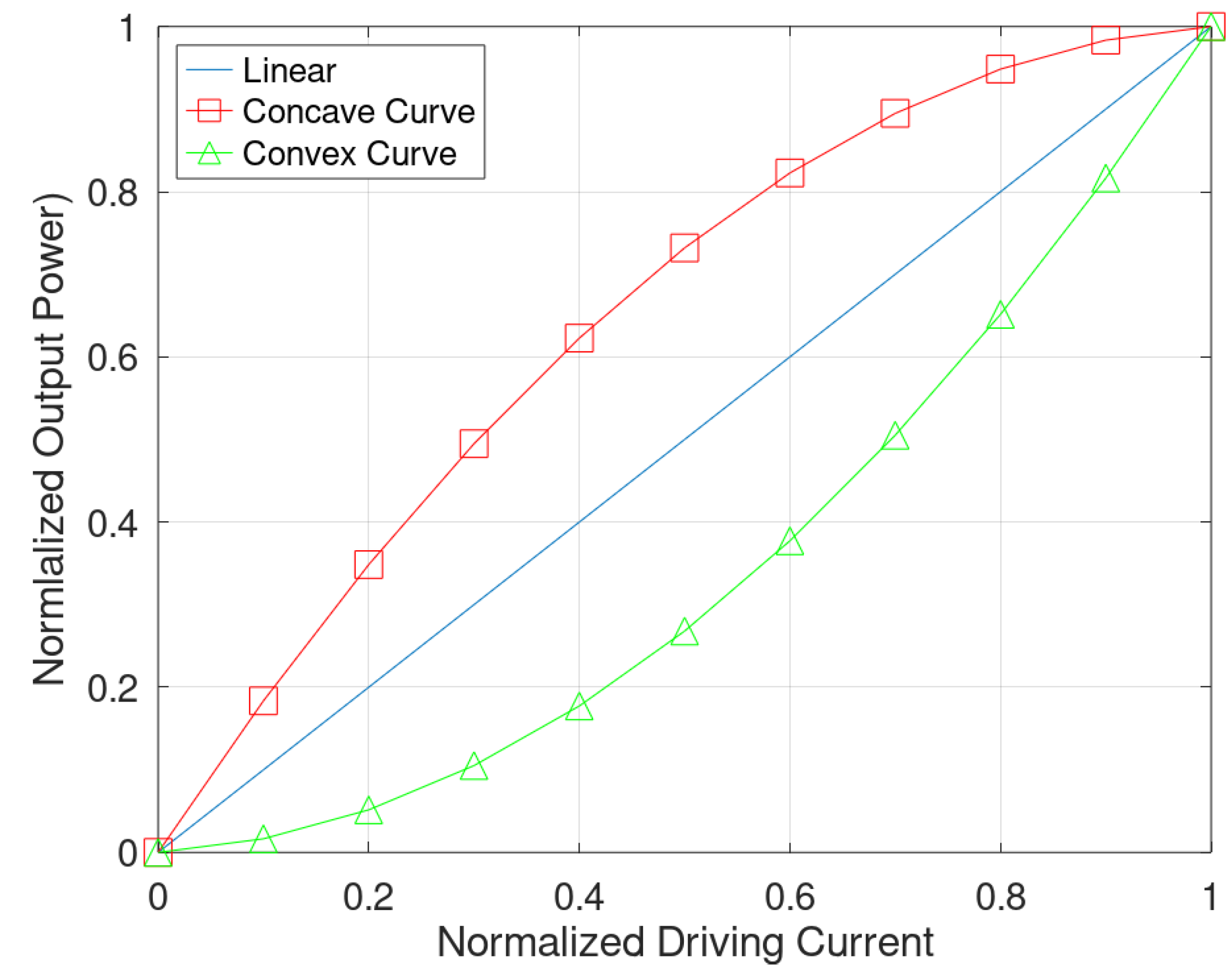
To describe the degree of nonlinearity, we define the nonlinearity parameter as
in the source transfer function. It is the normalized output power corresponding to the input current. For example, we assume that the LED has
, derived as the linear line in the transfer function shown in
Figure 2. If the transfer function is concave,
. If it is convex,
. LED is the prime example that has the concave characteristic [
12]. The coefficients of Equation (
2) can be expressed in
as follows [
11].
Figure 2 shows the concave and convex curve examples. In this figure, the concave curve is based on the red LED coefficient, but white and infrared LEDs also have concave curves. The experimental values of
according to LED type 85 are 0.732 in red LEDs, 0.541 in infrared LEDs, and 0.582 in white LEDs [
11]. However, the examples of fixed coefficient values given LED types in the assumption are not consistent in the natural environment. Depending on types and actual production, the coefficient value can be off. For that matter, it would be reasonable to solve LED distortion issues under two assumptions: (1) The LED nonlinear parameter value is a fixed one and consistent. (2) The LED nonlinear parameter value can vary for each LED and is inconsistent. Note that our term inconsistency does mean the slight change, not significant disruption, that the LED light-emitting type may be changed. Given these two assumptions, we need to investigate the solutions for the VLC system.
3. Initial Predistortion Modeling for LED Distortion Correction
As mentioned,
Figure 3 shows the OFDM-based visible light communication transceiver system, including a predistortion module. In the existing OFDM system without predistortion, the transmitter processes signals with Inverse Fast Fourier Transform (IFFT) after QAM modulation, and it expresses signals as the orthogonal frequency components. When the system processes the IFFT output signal via LED modulation and transmits LED output, its performance deteriorates due to the nonlinearity of LEDs and the generated distortion. The distortion causes signal to become noise-sensitive and damages the orthogonality between the frequency components. The result of the distortion is the substantially high error performance at the receiver. To resolve this problem, the predistortion module, as shown in
Figure 3, can compensate for LED nonlinear matters and is placed in front of the Digital-Analog Converter (DAC) for data transmission.
Since the goal is to design the predistortion module with the LED coefficient value, we describe initial predistortion modeling schemes and then coefficient approximation under the fixed value assumption for the predistortion module to compensate nonlinearity of LED luminance. Note that both models use the distortion characteristic of bias signals, and we discuss the nonfixed coefficient assumption case in the later section.
In the ideal condition, the primary method is to implement a predistortion by calculating the inverse function for Equation (
2). We can reformulate (
2) as
When we define
as the inverse function of Equation (
4), we can derive it as
where
is the input current to the predistortion module. Based on this inverse function, we can design the predistortion module and correct LED distortion.
4. Proposed Predistortion Model with Coefficient Approximation
Since the inverse method from (
5) includes a root within
, it does require the approximation approach within hardware modules for real-time implementation. For the VLC system, the approximation approach shown in the inverse function is impractical. We introduce a simple predistortion scheme using a simple coefficient approximation to mitigate this issue. We propose implementing the predistortion using the coefficient changed according to LED color without sampling the LED transfer function.
This method uses the static transfer function of Equation (
2). We modify coefficients
,
, and
in (
3) to the predistortion function. As mentioned, if
, the convex transfer function can be obtained. Therefore, the
value is substituted instead of
of (
3) and coefficients. Now, those coefficients can be expressed as follows.
When the coefficients in (
6) are substituted in (
2), the polynomial predistortion function
is
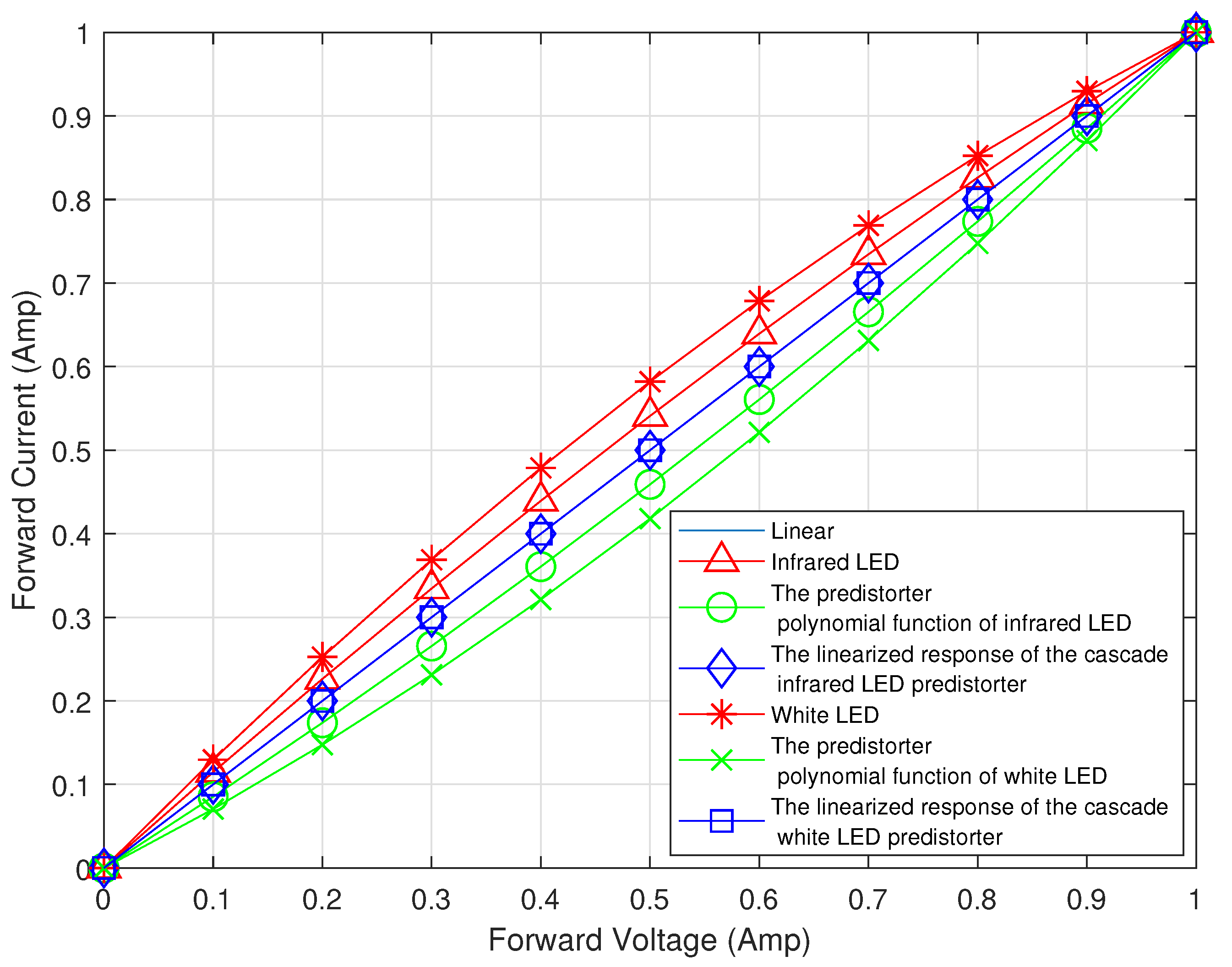
Figure 4 shows the nonlinearity of the LED, predistortion function, and linearized LED transfer function. Concave curves have a characteristic of the nonlinearity of the LED. Furthermore, convex curves are based on predistortion functions. If the predistortion function
enters the input
of the LED transfer function in (
2), the final transfer function becomes linear.
is determined according to the LED color. The proposed method can process if we know the LED color. Therefore, the sampling for making the predistortion like the conventional method is unnecessary. The proposed method has the advantage of simplicity when implementing the predistortion module.
5. Deep Learning Approach for Possible VLC System Enhancement
In previous sections, we showed our proposed predistortion scheme with the coefficient approximation for nonlinear distortion compensation based on the performance results. We also explained that coefficient approximation could be considered the practical approach for actual implementation. However, we believe that, in Rician fading, the proposed methods did not fully address LED nonlinearity issues in the two aspects. One is the modeling of LED distortion. The LED modeling formula, including our LED modeling, can often be ill-posed and poorly represented in LED distortion patterns.
In addition to the distortion modeling, each LED produced might not follow the same distortion characteristics as theoretical LED models, and our predistortion scheme based on the theoretical model may be ill-conditioned in the actual situation. Thus, instead of the LED modeling for correction, our focus must shift to the direct correction of LED distortion. For instance, our proposed approximation modeling schemes assume that the transmitter and receiver are stationary with the same coefficients. In the practical situation, the LED distortion coefficients can be different in each produced LED case, and a slight value-off can cause significant performance degradation. Hence, this VLC also has to correct LED distortion directly with the adaptation of these coefficient changes. To resolve the correction problem, we must consider using deep learning approaches, as the possible candidates.
To find the best estimate of the model of the data and systems, deep learning algorithms, such as CNN and LSTM, gained recent popularity in various communication systems applications, including VLC research. This deep learning approach can also be appliable to solve this distortion problem. In this paper, we introduce one of the deep learning applications for possible VLC system enhancement, the so-called BLSTM.
5.1. Bidirectional LSTM Approach for the Distortion Correction
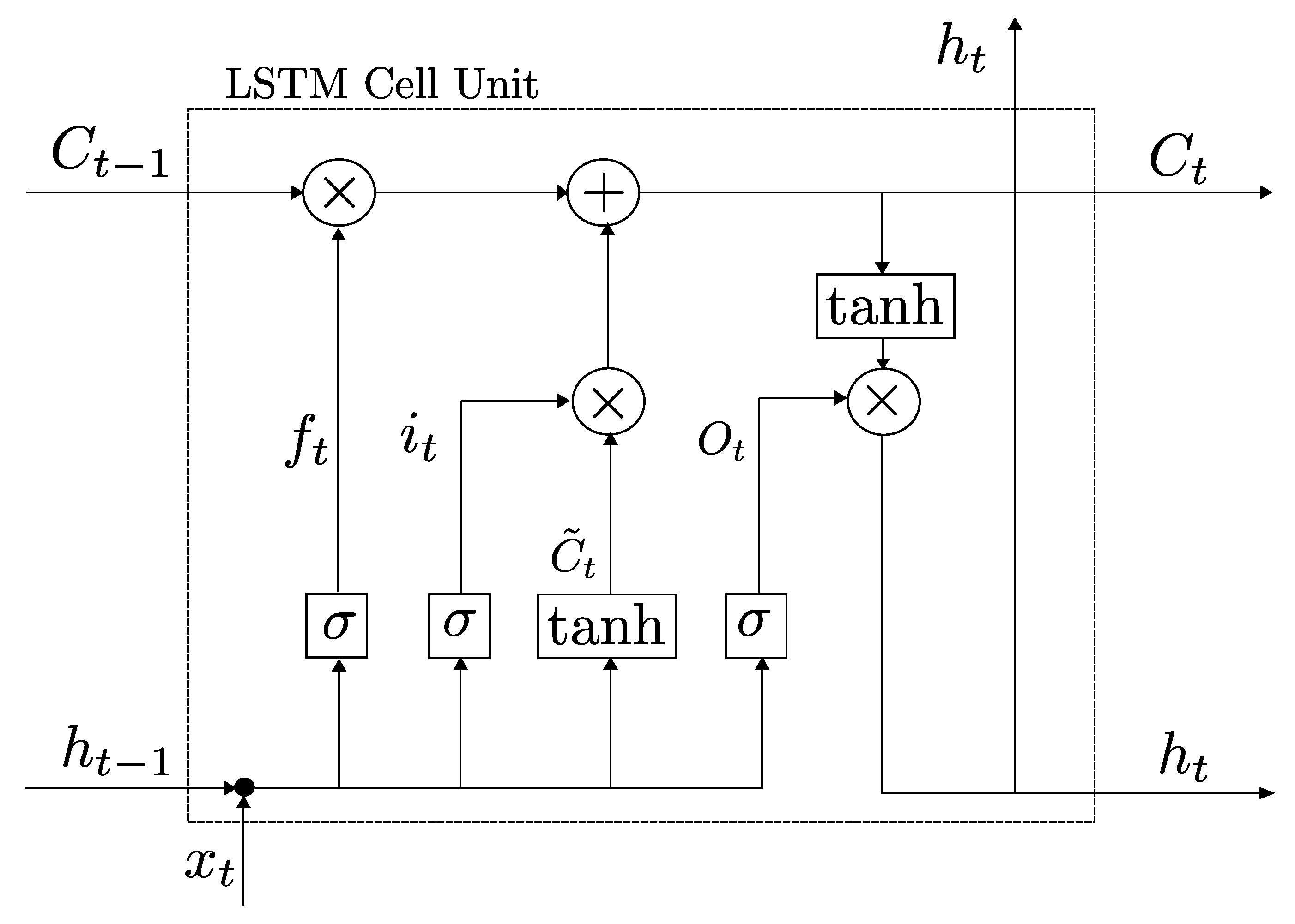
Unlike the classification and detection based on image processing, sequential data such as voice samples or text sentences correlate between present and past times. A Recurrent Neural Network (RNN) is the prime example of processing input data with network weights and structure. It also preserves the sequences of the data with the network hidden states. However, RNN has severe issues with vanishing and exploding gradient programs for the training and optimization process, resulting in the incapability of learning long-term knowledge. Long Short-Term Memory (LSTM) is one of the main algorithms to resolve these issues with RNN. LSTM contains multiple activation function modules called gates to overcome the gradient matters. This LSTM system contains memory that takes previous and current states as input, as shown in
Figure 5.
Each element in the LSTM unit, so-called a gate, leads the LSTM unit to store and discard the data information. Apart from input and output gates, the forget gate is another key LSTM feature that controls knowledge preservation in LSTM units. Details of each parameter in
Figure 5 are below [
13,
14]. Note that
and tanh are defined as the sigmoid function and the hyperbolic tangent activation function.
Note that , , , , and are the input gate, forget gate, memory cell, output gate, and hidden state at time step t, respectively. In addition, , , , and are the input weight matrices of parameters i, f, O, and , and , , , and are the hidden layer weight matrices of parameters i, f, O, and . In each formula, , , , and are the biased parameters for i, f, O, and . Once the LSTM unit took previous memory cells and hidden states from the previous LSTM units as and , it processed the following sequential input at times t and to produce the present memory cell and hidden state, and .
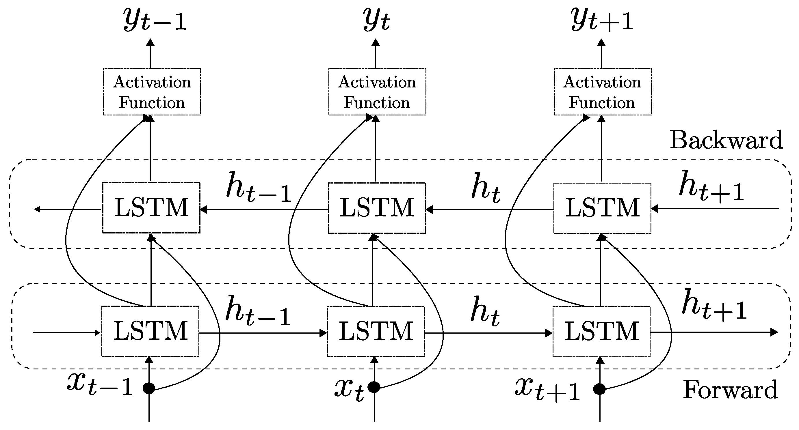
As illustrated in this general structure of the LSTM unit, the data sequence is a forward sequence. However, the data sequence information in forward and backward sequences can be different, and understanding the backward data sequence can produce the data prediction well. These are the main reasons why Bidirectional LSTM should be considered.
A brief block diagram of the BLSTM structure is shown in
Figure 6. In this figure, the BLSTM first processes the forward LSTM before processing the backward LSTM, and the activation function produces the result [
15]. Hence, this system contains the past and future input data.
BLSTM is a significant advancement of LSTM schemes that train the neural networks with the forward and backward data sequences [
17]. Eventually, it aims to train with the data sequences to correct or predict future data. Existing example applications include speech recognition and stock index prediction [
18]. Since our VLC systems process continuous time-domain signal data, LSTM becomes a suitable option for distortion correction. However, traditional LSTM trained in the forward direction of the data or signal sequence can become biased for signal correction. On the other hand, Bidirectional LSTM processes the backward and forward of the signal sequences to train both sequence directions of the signal. We consider the BLSTM for distortion correction in this paper.
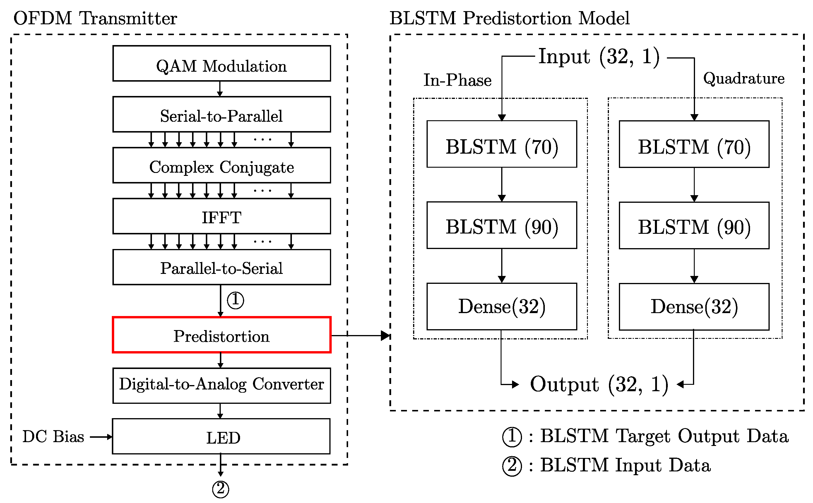
5.2. Proposed Initial BLSTM-Based VLC System
From our VLC perspective, since the distortion occurs in the transmitter, it would be reasonable to conduct the predistortion on the transmitter instead of the receiver.
Figure 7 shows that the predistortion module must be placed right before the diode. In the predistortion module, our BLSTM models are double in parallel, and each BLSTM structure is designed with two BLSTM layers and a dense layer. For the correction purpose, the output length of the BLSTM should be equivalent to the input length. Note that, due to the system complexity and hardware capability, we designed the OFDM system with an FFT size of 32.
Several properties must be carefully considered for BLSTM design and training, such as batch size, epoch, and data size. Since these parameters can impact the predistortion correction performance, our investigation extended these parameters into our scope. Once the BLSTM models are completed to train, the models are placed in the transmitter for continuous use. When the VLC system conditions and environments are changed, we need to retrain the BLSTM model, which is highly unlikely in the in-building environmental case.
6. Experiment Setup and Results
For the experiment result, we operated two experiments: (1) coefficient approximation-based predistortion modeling and (2) BLSTM application. Note that we do not compare both approaches directly in this paper since each has a different assumption.
To produce the results of VLC performances with coefficient-approximation-based predistortion, given measured static transfer functions of white and infrared LEDs, a quadratic polynomial of the LED in Equation (
2) was applied as the general model of the transfer function. This polynomial approximation has been widely popular to model nonlinearity characteristics of LED or laser diodes [
19]. Each graph shows two QAMs in the simulation: 16 and 64.
For BLSTM experiment settings, we considered the input data as the distorted IFFT signal and target output data as the IFFT signal after the LED shown in
Figure 7. We utilized our distortion model (
2) to generate the distorted IFFT signal, but any distortion model or existing data based on an LED can be applied for the training. After our initial investigation, we confirmed that the BLSTM length must be more than input data size, which was 32 in our case. We also had to consider the limitation of computing resources and model complexity as well. With considering our investigation and limitation, we set the length of the Bidirectional LSTM as 70 and 90 for the first and second layers. Since we considered the indoor mobility service as an operation environmental condition, we considered the Rician fading with K factors from 4 to 20. For details of the BLSTM experiment setting, the complete list of properties and experiment settings is in
Table 1. In
Table 1, note that we used at least more than 25 million samples for experiment.
6.1. Experiment Results of Predistortion Modeling with Coefficient
Approximation
We simulated the QAM performances of two predistortion schemes using (1) the inverse function and (2) coefficient approximation along with the conventional scheme without predistortion. Note that we set the simulation threshod as the BER reached to .
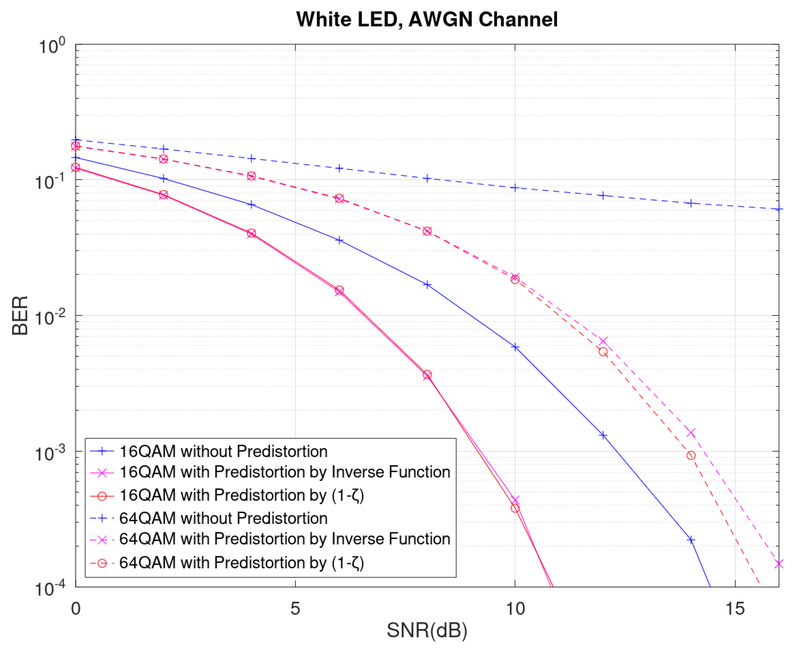
Figure 8 shows OFDM’s BER performance using 256 subcarriers in 16 QAM and 64 QAM for the white LED. The results showed a 3.5 dB performance gain for all predistortion schemes at BER
in 16 QAM. For BER
at 64 QAM modulation, each predistortion required us to set SNR values at 16.5 dB in the inverse function scheme and 17 dB in the coefficient modification scheme. In addition, the BER performance were deteriorated when QAM levels were increased since symbols were closer in the constellation diagram.
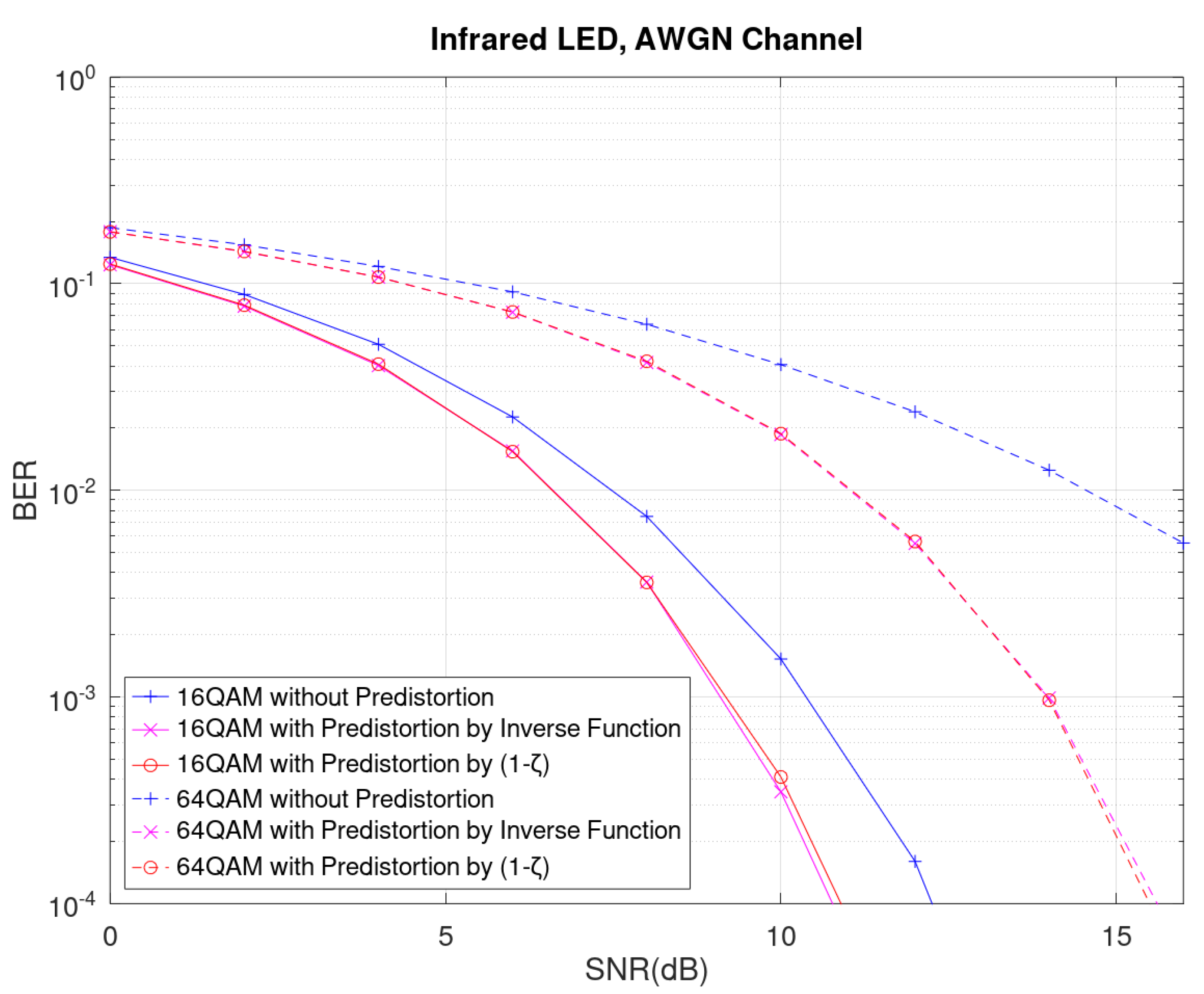
Figure 9 shows OFDM’s BER performances using 256 subcarriers in 16 QAM and 64 QAM. In these simulations, we used the infrared LED. In this case, we also observed that both predistortion schemes gained 1.5 dB performance at BER =
with 16 QAM compared to the scheme without predistortion. For 64 QAM modulation to meet target BER
, both predistortion schemes needed to set SNR values up to 16.5 dB.
To summarize the results from
Figure 8 and
Figure 9, the white LED performance was substantially improved compared to the infrared LED performance. However, the overall BER performances of the white LED with predistortion schemes were still inferior to infrared LED performance since the infrared LED operates on a lower frequency spectrum than the white LED does. In addition, infrared LED performance without predistortion had 2 dB more SNR gain than the white LED performance without predistortion.
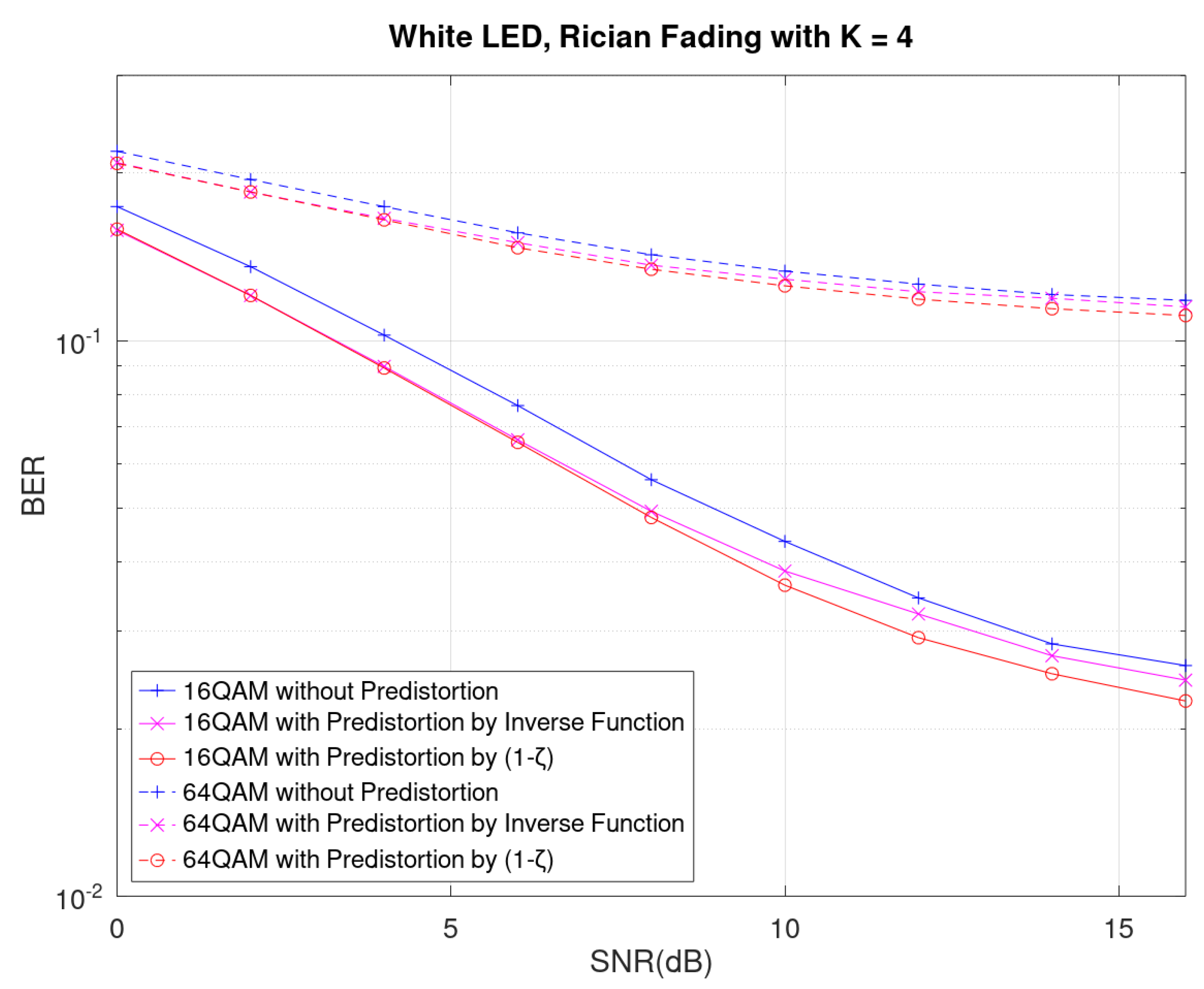
Given the Rician fading conditions, our performance results showed that the Rician fading might alter the performance. As shown on the Rician fading results in
Figure 10, the performance of the coefficient approximation predistortion method was still better than that without any predistortion in low SNRs. Our results may conclude that the predistortion modeling may mitigate the distortion matter but still can be affected by other conditions in terms of Rician fading impacts.
6.2. Experiment Results of BLSTM Application
For the BLSTM experiment, we looked for three aspects: (1) performance impacts on BLSTM parameters including batch size, data size, and epoch, (2) performance on K factor values, and (3) performance over SNR. Since the distortion correction was trained at the transmitter, we confirmed that SNR does not influence the training process but on the test. We also considered the Rician fading for our experiment due to the possible mobility service scene. The first preliminary experiment result is in
Figure 11. In this graph, we can confirm that once the K factor is increased, the VLC performance is improved as well. For BLSTM-specific testing, we considered K factors 4 and 20 as the worst and best cases.
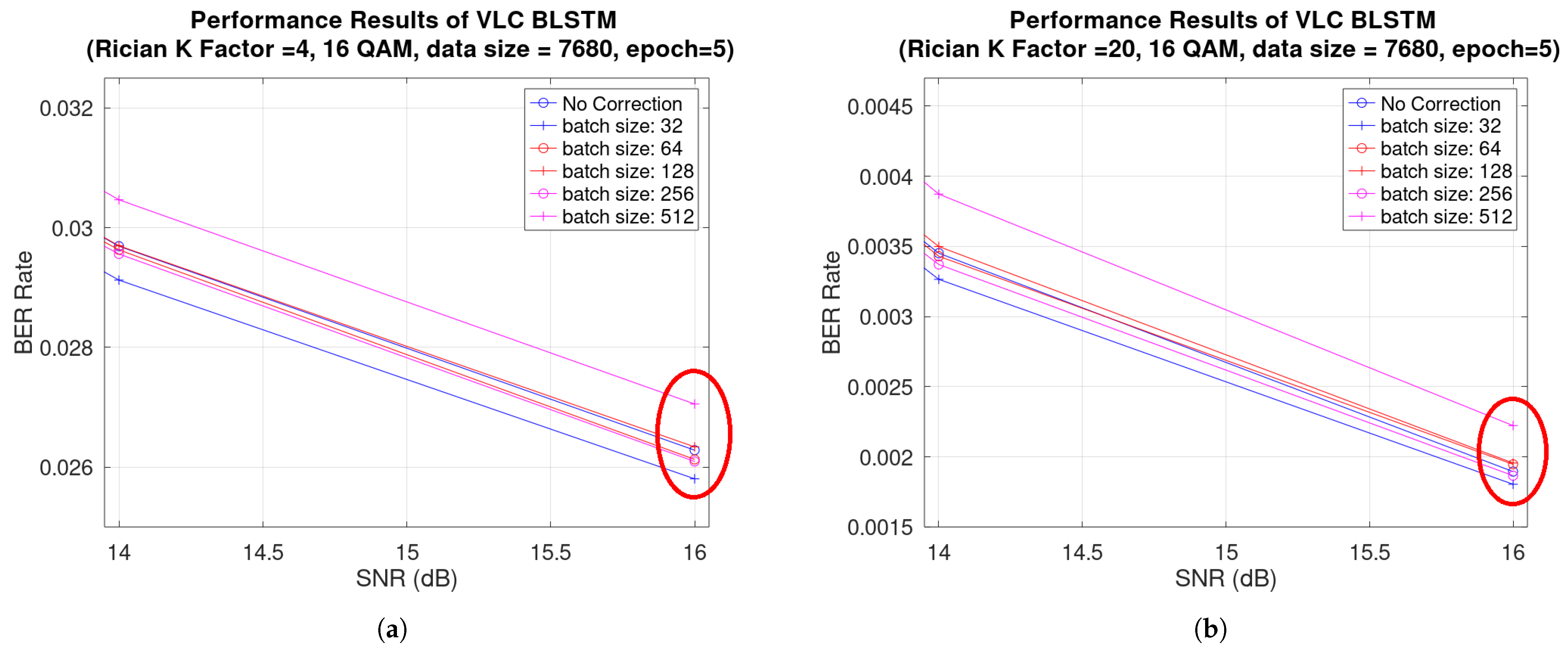
The performance results over batch size are in
Figure 12. In
Figure 12a,b, we observe that when batch sizes were 32 and 256, the VLC outperformed as compared to the no correction case. Note that batch size with 64 was outperformed on a K factor with 4 but underperformed on a K factor with 20. Based on the results, we may conclude that batch size is one of the critical parameters to tune the performance in a sophisticated manner.
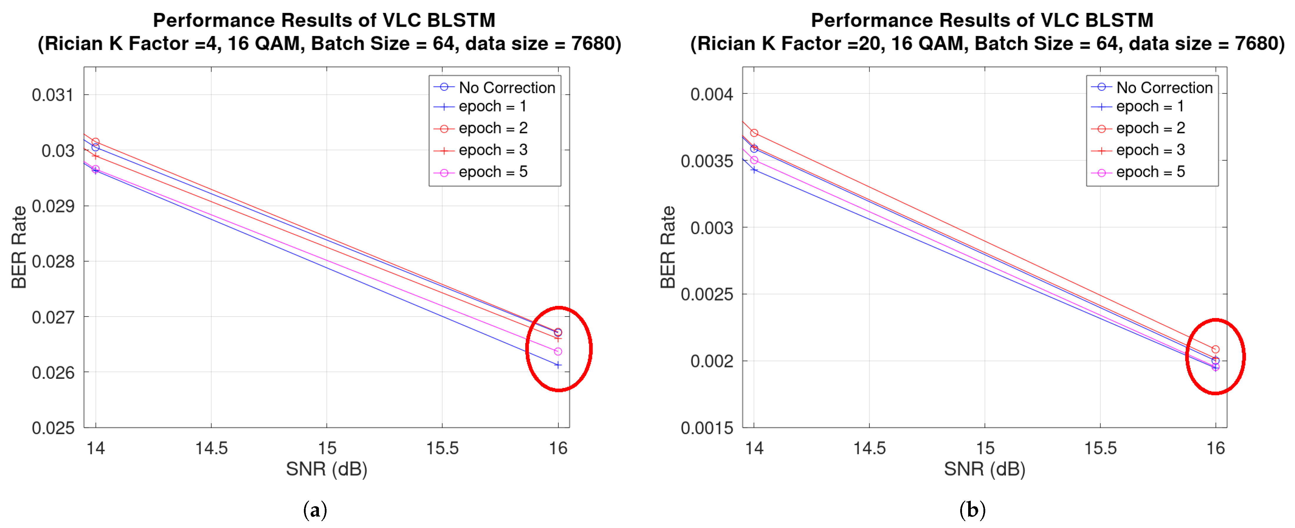
The performance results over the epoch are in
Figure 13. In
Figure 13a,b, we observe that when the epoch was 1 and 5, the VLC outperformed as compared to the no correction case. Note that, as time goes by, the more the number of epochs increases, the more performance improvement is shown. Underperformed cases with epochs 2 and 3 proved that very few training iterations do not significantly improve performance.
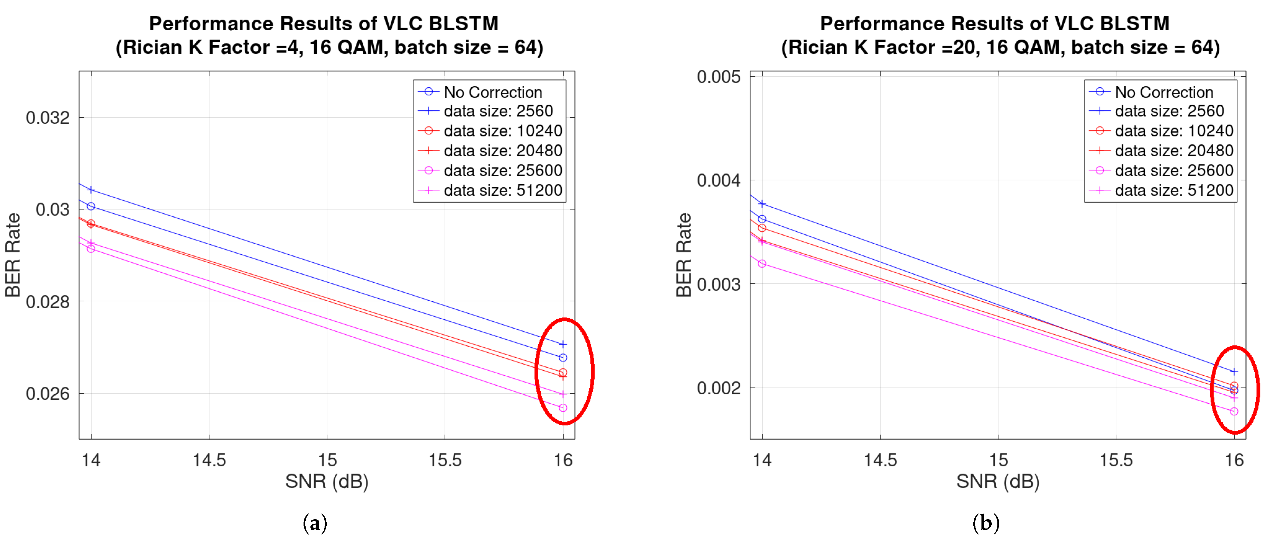
The performance results over data size are in
Figure 14.
Figure 14a,b show that when data sizes were approximately over 204.8 million, the VLC outperformed much more than in the no correction case. The performance results proved that, during the training process, sufficient data must be prepared and, in our case, over about 205 million samples are required to produce better performance. Insufficient data size may cause overfitting problems, and the VLC system performs worse than in the no correction case.
The BER performance of each batch size over SNR is in
Figure 15. The figure shows that the performance deteriorates when the batch size is increased. However, we also have to understand that the batch size is equivalent to the step size in the optimization. Given that each iteration time is fast when the batch size is large, the trade-off between batch size and iteration time must be carefully considered under limited resources and time.
To summarize, our BLSTM models showed the possible performance improvement of LED distortion. In addition, we only need to care for the transmitter AND no requirement for the receiver to operate this approach. As described in the in-building mobility service in
Section 1, the mobility devices, including IoT applications, can use the same receiver structure while experiencing enhanced BER performance of the VLC system. In other words, they can spend less energy on the same VLC system experiences.
7. Conclusions
In our paper, we observed the nonlinearity of LEDs, and it could significantly affect the performance of optical OFDM transceiver systems. The compensated module using predistortion can substantially enhance the OFDM system performance for performance improvement. However, the existing compensation methods directly have to measure LED nonlinearity or high complex characteristics. In the OFDM-based VLC system, we proposed the practical predistortion scheme with coefficient approximation. The coefficient approximation showed the effectiveness of simple operations without a necessary sampling of the LED transfer function by using the inverse function. By simply tuning the coefficient, the OFDM system showed outperformed results compared to the system without the predistortion.
In addition, we proposed a Bidirectional LSTM model to handle the variation and distortion of LEDs without distortion modeling. We used the distortion data from our distortion models for the training purpose, and the results showed the possible promise of performance improvement. Possible discussion associated with BLSTM approaches is as follows.
We used the simple BLSTM structure and improved distortion. However, our BLSTM structure did not address the phase issues. Since the BLSTM model cannot handle complex number data, we separated real and imaginary data and produced two models. No consensus existed between the two trained models. A significant performance improvement could be possible if we designed the BLSTM model with an interconnected structure.
We considered the white LED case only in this experiment. To process red and infrared LEDs, BLSTM models have to be retrained. Even if we retrained the model, it is not guaranteed whether or not those models can produce the equivalent performance on those diodes. Diode-specific model structure must be explored.
Assuming we have no prior knowledge of LEDs, the distortion correction with one model would simplify the system structure and reduce its complexity. To handle all LED distortion into one model, we may need to design a deep learning structure more complex than our tested BLSTM model.
For our BLSTM model training, computing power is the primary factor in our proposed VLC scheme, and our initial studies encountered the limitation of the computing resources. Our future works must extend to various BLSTM layer lengths and structures, assuming we have considerable computer powers. When the VLC scheme becomes part of the 5G NR light radio family, possible opportunities for our BLSTM model are available to be trained into the cloud or multi-access edge computing (MEC) on a large scale.
In addition to our work, it would be possible to extend our BLSTM approach to the practical and effective implementation of the predistortion module and explore other deep learning models and structures dedicated to the hardware module in VLC systems for possible future work.
Author Contributions
Conceptualization, Y.-J.P. and J.-Y.K.; methodology, Y.-J.P. and J.-Y.K.; software, Y.-J.P. and J.-Y.K.; validation, Y.-J.P. and J.-Y.K.; investigation, Y.-J.P., J.-Y.K. and J.-I.J.; resources, Y.-J.P. and J.-I.J.; data curation, Y.-J.P. and J.-Y.K.; writing, Y.-J.P., J.-Y.K. and J.-I.J.; visualization, Y.-J.P. and J.-Y.K.; supervision, Y.-J.P., J.-Y.K. and J.-I.J.; project administration, Y.-J.P., J.-Y.K. and J.-I.J. All authors have read and agreed to the published version of the manuscript.
Funding
This work was supported by the Sungshin Women’s University Research Grant of 2021 and the Technology Innovation Program (20013726, Development of Industrial Intelligent Technology for Manufacturing, Process, and Logistics) funded by the Ministry of Trade, Industry and Energy (MOTIE, Korea).
Conflicts of Interest
The authors declare no conflict of interest.
Abbreviations
The following abbreviations are used in this manuscript:
| LED | Light-Emitting Diode |
| OFDM | Orthogonal Frequency Division Multiplexing |
| ACO-OFDM | Asymmetrically Clipped Optical OFDM |
| DCO-OFDM | Direct-Current-biased Optical OFDM |
| DC | Direct Current |
| AWGN | Additive White Gaussian Noise |
| BER | Bit-Error Rate |
| VLC | Visible Light Communication |
| QAM | Quadrature Amplitude Modulation |
| IFFT | Inverse Fast Fourier Transform |
| FFT | Fast Fourier Transform |
| SNR | Signal-to-Noise Ratio |
| RNN | Recurrent Neural Network |
| LSTM | Long Short-Term Memory |
| BLSTM | Bidirectional Long Short-Term Memory |
References
- Cabric, D.; Chen, M.; Sobel, D.; Yang, J.; Brodersen, R. Future Wireless Systems: UWB, 60 GHz, and Cognitive Radios. In Proceedings of the IEEE 2005 Custom Integrated Circuits Conference, San Jose, CA, USA, 21 September 2005; pp. 793–796. [Google Scholar]
- Kahn, J.; Barry, J. Wireless Infrared Communications. Proc. IEEE 1997, 85, 265–298. [Google Scholar] [CrossRef] [Green Version]
- Katz, M.; Ahmed, I. Opportunities and challenges for visible light communications in 6G. In Proceedings of the 2020 2nd 6G Wireless Summit (6G SUMMIT), Levi, Finland, 17–20 March 2020; pp. 1–5. [Google Scholar]
- Santa, J.; Bernal-Escobedo, L.; Sanchez-Iborra, R. On-board unit to connect personal mobility vehicles to the IoT. Procedia Comput. Sci. 2020, 175, 173–180. [Google Scholar] [CrossRef]
- Elgala, H.; Mesleh, R.; Haas, H.; Pricope, B. OFDM Visible Light Wireless Communication Based on White LEDs. In Proceedings of the 2007 IEEE 65th Vehicular Technology Conference—VTC2007-Spring, Dublin, Ireland, 22–25 April 2007; pp. 2185–2189. [Google Scholar]
- Bahai, A.; Singh, M.; Goldsmith, A.; Saltzberg, B. A New Approach for Evaluating Clipping Distortion in Multicarrier Systems. IEEE J. Select. Areas Commun. 2002, 20, 1037–1046. [Google Scholar] [CrossRef]
- Armstrong, J.; Lowery, A. Power efficient optical OFDM. Electron. Lett. 2006, 42, 370–372. [Google Scholar] [CrossRef] [Green Version]
- Elgala, H.; Mesleh, R.; Haas, H. Predistortion in Optical Wireless Transmission using OFDM. In Proceedings of the 2009 Ninth International Conference on Hybrid Intelligent Systems, Shenyang, China, 12–14 August 2009; Volume 2, pp. 184–189. [Google Scholar]
- Kim, J.K.; Hyun, K.; Park, S.K. Adaptive predistorter using NLMS algorithm for nonlinear compensation in visible-light communication system. Electron. Lett. 2014, 50, 1457–1459. [Google Scholar] [CrossRef]
- Lee, T.P. The nonlinearity of double-heterostructure LED’s for opticalcommunications. Proc. IEEE 1977, 65, 1408–1410. [Google Scholar] [CrossRef]
- Inan, B.; Lee, S.C.J.; Randel, S.; Neokosmidis, I.; Koonen, A.M.J.; Walewski, J.W. Impact of LED Nonlinearity on Discrete Multitone Modulation. IEEE/OSA Opt. Commun. Netw. 2009, 1, 439–451. [Google Scholar] [CrossRef]
- Ramirez-Iniguez, R.; Idrus, S.; Sun, Z. Optical Wireless Communications-IR for Wireless Connectivity, 1st ed.; Auerbach: Boca Raton, FL, USA, 2008; Volume 6. [Google Scholar]
- Zhu, Y.; Gong, C.; Luo, J.; Jin, M.; Jin, X.; Xu, Z. Indoor Non-Line of Sight Visible Light Communication with a Bi-LSTM Neural Network. In Proceedings of the 2020 IEEE International Conference on Communications Workshops (ICC Workshops), Dublin, Ireland, 7–11 June 2020; pp. 1–6. [Google Scholar]
- Smagulova, K.; James, A.P. A survey on LSTM memristive neural network architectures and applications. Eur. Phys. J. Spec. Top. 2019, 228, 2313–2324. [Google Scholar] [CrossRef]
- Sunny, M.A.I.; Maswood, M.M.S.; Alharbi, A.G. Deep learning-based stock price prediction using LSTM and bi-directional LSTM model. In Proceedings of the 2020 2nd Novel Intelligent and Leading Emerging Sciences Conference (NILES), Giza, Egypt, 24–26 October 2020; pp. 87–92. [Google Scholar]
- Imrana, Y.; Xiang, Y.; Ali, L.; Abdul-Rauf, Z. A bidirectional LSTM deep learning approach for intrusion detection. Expert Syst. Appl. 2021, 185, 115524. [Google Scholar] [CrossRef]
- Amran, N.A.; Soltani, M.D.; Yaghoobi, M.; Safari, M. Deep learning based signal detection for OFDM VLC systems. In Proceedings of the 2020 IEEE International Conference on Communications Workshops (ICC Workshops), Dublin, Ireland, 7–11 June 2020; pp. 1–6. [Google Scholar]
- Althelaya, K.A.; El-Alfy, E.S.M.; Mohammed, S. Evaluation of bidirectional LSTM for short-and long-term stock market prediction. In Proceedings of the 2018 9th International Conference on Information and Communication Systems (ICICS), Irbid, Jordan, 3–5 April 2018; pp. 151–156. [Google Scholar]
- Daly, J.C. Fiber optic intermodulation distortion. IEEE Trans. Commun. 1982, 30, 1954–1958. [Google Scholar] [CrossRef]
| Publisher’s Note: MDPI stays neutral with regard to jurisdictional claims in published maps and institutional affiliations. |
© 2022 by the authors. Licensee MDPI, Basel, Switzerland. This article is an open access article distributed under the terms and conditions of the Creative Commons Attribution (CC BY) license (https://creativecommons.org/licenses/by/4.0/).


