Communication

A Low-Frequency Magnetic Field Sensor Based on Fiber Bragg Gratings

1
Department of Electronic Engineering, Feng Chia University, Taichung City 407802, Taiwan
2
Department of Electrical Engineering, Fu Jen Catholic University, New Taipei City 242062, Taiwan
3
Department of Electrical Engineering, Feng Chia University, Taichung City 407802, Taiwan
*
Author to whom correspondence should be addressed.
Photonics 2022, 9(2), 102; https://doi.org/10.3390/photonics9020102
Submission received: 9 January 2022 / Revised: 29 January 2022 / Accepted: 10 February 2022 / Published: 11 February 2022
(This article belongs to the Special Issue Advancements in Fiber Bragg Grating Research II)

Abstract

:
A new type of low-frequency magnetic-field sensor based on fiber Bragg gratings (FBGs) was experimentally demonstrated for measuring the DC to low-frequency magnetic field. The operating mechanism of this AC magnetic sensor is based on the strain exerted by a loaded magnet on the sensing structure, which causes center-wavelength shifts of FBG. The achieved sensitivity was 8.16 pm/G with a resolution of 3 Gauss at ambient conditions. The proposed FBG magnetic sensor is easy to use, compact, and suitable for DC to low-frequency magnetic sensing applications.

1. Introduction

Super-low-frequency (SLF = 30–300 Hz) magnetic fields appear commonly in the city environment, where typical sources include high-voltage transmission towers and electrical appliances. Epidemiological studies suggested that there is a correlation between SLF magnetic field exposure and adverse health effects such as cancer [1,2], and monitoring of the daily dosage of the SLF magnetic field is therefore important in risk assessment. In addition, the SLF prospecting technique has also been successfully implemented in geothermal exploration and coalbed methane reservoir interpretation [3]. In this context, a SLF magnetic sensor with an affordable and compact probe that meets engineering requirements is essential for SLF applications.
SLF magnetic sensing techniques utilize a broad range of physics and chemistry methodologies, including Faraday search coils [4], optically pumped magnetometers [5], magnetic resonant spins [6], superconducting quantum interference devices (SQUIDs) [7], Hall effect sensors [8], magneto-resistive sensors [9], and optical magnetic sensors. Although some of the magnetic detectors achieve state-of-the-art magnetic sensitivity in the sub-nanotesla range, such as SQUID-based laboratory sensors [10], their large sensor size obscures practical applications. Importantly, the majority of the magnetic sensors operating at DC to SLF are highly influenced with readout electronics [11], limiting their suitability for use by electromagnetic interference in certain environments. On the other hand, optical magnetic sensors such as fiber optic sensors offer many strengths, such as immunity to electromagnetic perturbation, a compact and portable sensor head, remote sensing capability, and high magnetic sensitivity [12].
Recently, fiber Bragg grating (FBG)-based sensors stand out as a promising sensors among the aforementioned optical magnetic sensors [13,14,15,16]. As FBG is designed to reflect light in a narrow band of wavelengths, the composition of FBGs could encode optical pulse signals in both the time and frequency domain, and hence is more suitable to achieve wavelength division multiplex (WDM). In principle, the FBG sensor is based on Bragg wavelength drift [17] and has inaccurate issues in cross-sensitivity of strain and temperature [18]. Therefore, wavelength detection and temperature compensation are accordingly critical in wavelength-coded FBG sensors. Here we proposed a simple optical sensor for a SLF magnetic field utilizing FBG which is not sensitive to temperature fluctuation, and is suitable for monitoring daily exposure to SLF magnetic field as well as magnetic inspection, depth sounding, and other SLF applications. The proposed FBG magnetic sensor is based on the sensing ability of FBG to strain or pressure [19], which is applied to the sensor by an attached magnet within the sensor structure. Experimental results show that the proposed SLF magnetic sensing element responds well to magnetic field with frequency below 120 Hz. An average magnetic sensitivity of approximately 8.16 pm/G was achieved.

2. Materials and Methods

The FBG sensor structure is shown in Figure 1. A small neodymium magnet with magnetic dipole m was glued in a sensing hole on the side of FBG structure. The structure size: length 40 mm, width 20 mm, and height: 20 mm. The diameter of the sensing hole is 12 mm and is located at the center of the side surface. We filled the sensor structure with a chunk of soft polymer and an embedded FBG [19]. A pair of gaskets was used to enclose the chunk polymer and to fix both sides of the fiber which improves the sensing performance. When the magnet is in the presence of an external AC magnetic field B A C , the magnetic force causes the magnet to squeeze the enclosed polymer with an axial strain ε to the FBG. For a magnetic dipole m coupled to an external magnetic field B A C , the magnetic force is
F = ( m · B A C ) ,  
The strain ε exerted on the polymer could then be expressed in terms of the magnetic force by
ε = c ( m · B A C ) ,
where c is a parameter depending on the geometry of the magnet and FBG sensor structure. The strain ε then changes the effective index and grating period of the FBG, which induces the grating wavelength to shift. The relationship between the grating wavelength shift ( Δ λ B ) and the axial strain applied to the FBG is given by [20]:
Δ λ B λ B = ( 1 P e ) ε  
where P e represents the effective photo-elastic coefficient of the glass fiber. In a typical fiber material
P e = n n e f f 2 [ P 12 v ( P 11 + P 12 ) ] / 2 ,
where n n e f f is the effective refraction index, υ is the Poisson’s ratio, and P 11 and P 12 are elements of the strain-optic tensor. According to Equations (2) and (3), it follows that the shifting of the grating wavelength Δ λ B of the FBG is then proportional to the applied magnetic field B A C :
Δ λ B λ B = c ( 1 P e ) | ( m · B A C ) | ,
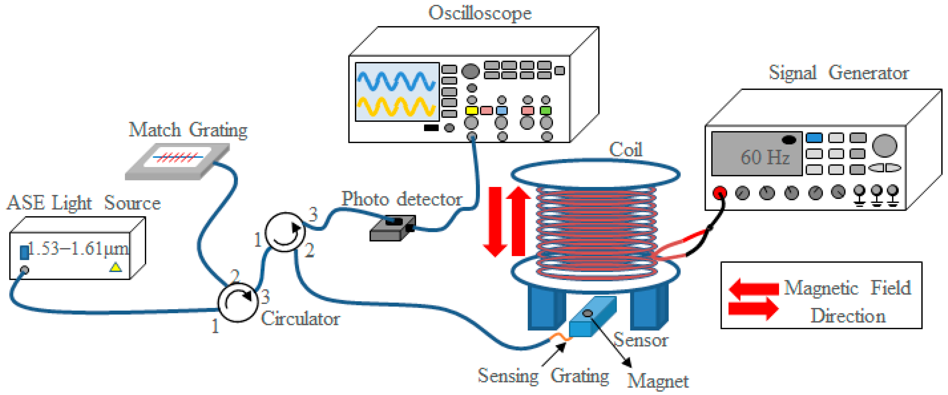
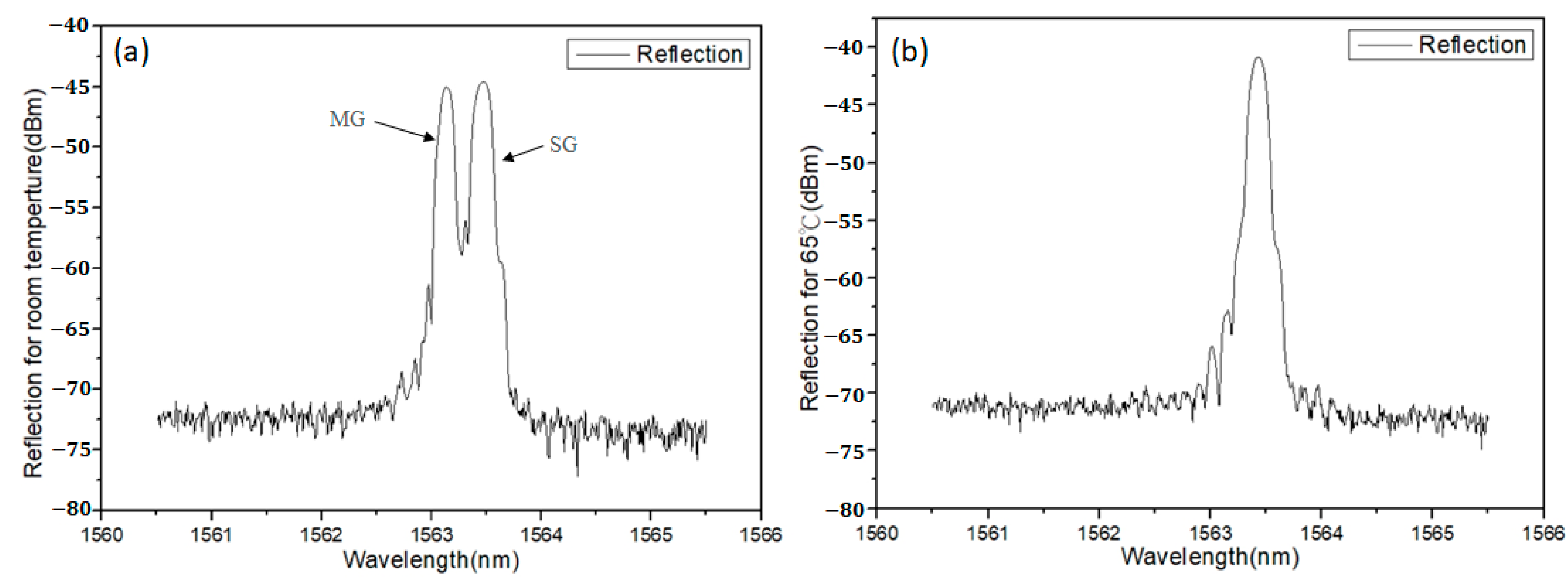
The experimental setup is shown in Figure 2, in which two FBGs were used. One was used as the sensing grating (SG) in the FBG sensor, and the other was used as a matching grating (MG) for obtaining the overlapped signals of the two gratings to be detected by the photo detector (PDA10CS, Thorlabs, Newton, NJ, USA). A laser light of wavelength 1.53–1.61 μm (ASE FL7002, Thorlabs, Newton, NJ, USA) was fed through 2 circulators such that the sum of SG and MG signals were sent to a photodetector. The purpose of using a MG is to get an almost simultaneous response for sensing the magnitude variation of low frequency AC magnetic field. This is due to the various overlapping intensity created from the overlapping area of both the sensing grating and matching grating spectra. Variation in the AC magnetic-field magnitude caused the permanent magnet of the sensing head to modulate the magnetic force and then resulted in a shift in the sensing grating wavelength. In the end, two gratings’ overlapping intensity over time was monitored as electrical signals shown in oscilloscope via an optical power detector. The matching grating also has the function of temperature compensation so that the SG will always have an identical wavelength shift under different temperatures. The MG was placed in a temperature-control oven such that the thermal expansion of grating period tuned the wavelength for reflected reference light, as shown in Figure 3. Therefore, the proposed FBG sensor system is immune to temperature fluctuation in ambient air owing to the temperature-compensated MG.
For the AC magnetic-field measurement, the AC magnetic field at SLF was generated from a solenoid driven by a function generator at different frequencies. The sensor structure is 3D printed with Z-ABS resin and filled with elastic polymer (CrownCrete USC 810, Crown Polymers, Huntley, IL, USA). The elastic polymer here was produced by mixing the USC810 resin with its hardener in an appropriate proportion, in which the viscoelasticity of the polymer gives a reasonable response (storage modulus) and phase lag (loss modulus) to oscillatory driving force at super-low frequency [21].

3. Results

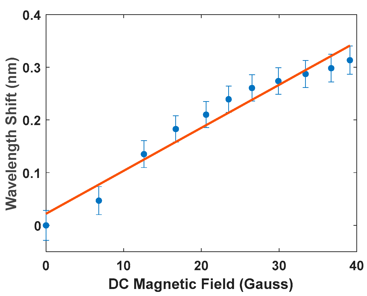
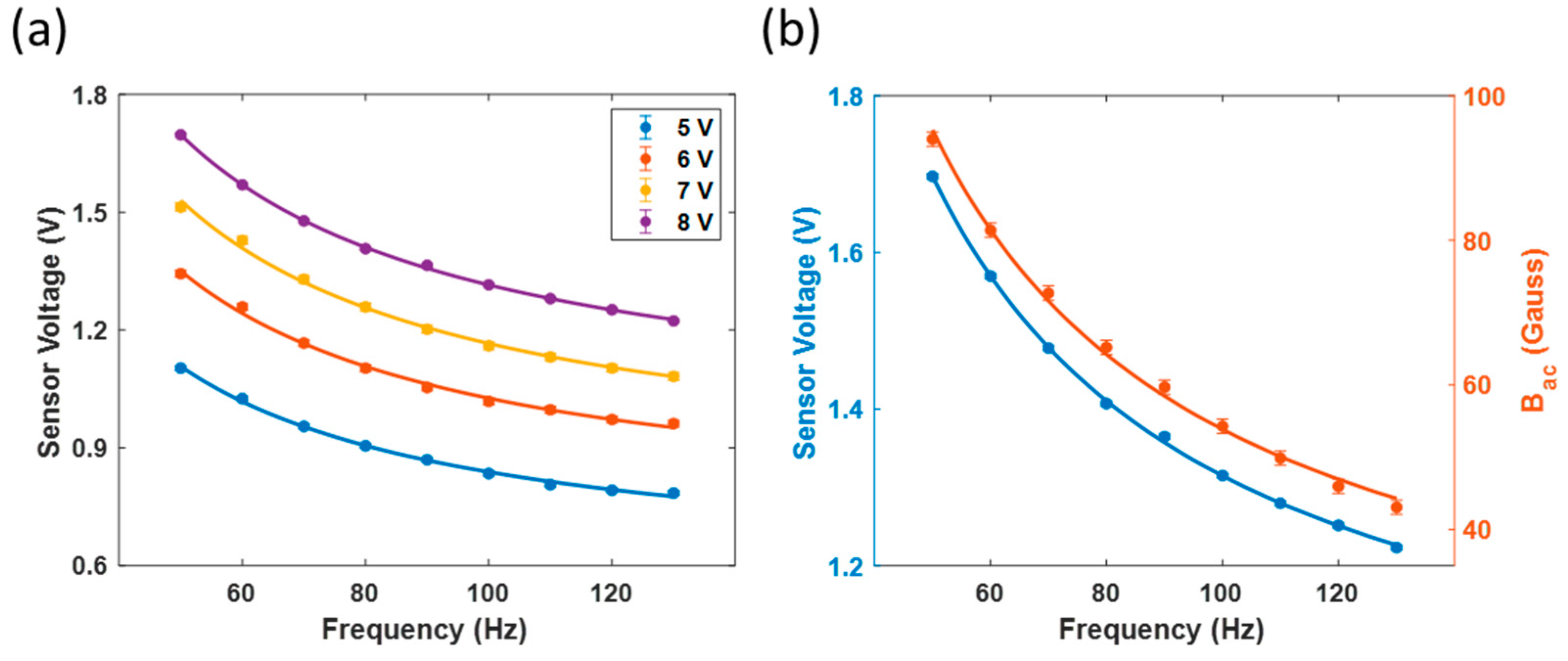
The experimental results of the DC magnetic field measurement are shown in Figure 4, in which the slope of the curve shows a DC magnetic sensitivity η = 0.00816   nm / G . Given a fitting error of 25 pm, we achieved a minimum detectable magnetic field (magnetic resolution) of Δ B A C = e r r o r · η = 3 Gauss. The measured root-mean-square (RMS) voltage signal versus AC magnetic field frequency at a distance of 1 cm between coil and sensor is plotted in Figure 5a. The AC magnetic field was also recorded with a Gauss meter (5180, F.W. Bell Inc., Portland, OR, USA), and the measured RMS AC magnetic field versus frequency is depicted in Figure 5b. The recorded magnetic field versus frequency curve with the Gauss meter is consistent with FBG sensor signals. Throughout the entire measurement of AC magnetic field with our FBG sensor in the manuscript, we had repeated the same sequence of measurements over half a dozen times and found out the difference between each repetition was less than 1%. With a projected magnetic field resolution around 3 Gauss at 120 Hz, we deducted an AC magnetic sensitivity of 3   Gauss / 120   Hz = 9   μ T / Hz for our FBG sensor at super low frequencies. The lower signals of FBG sensor at higher frequency could be attributed to the facts that the impedance Z of the solenoid is proportional to the driven frequency ω. The impedance of the solenoid can be given by an inductor formula:
Z = R + j ω L ,
where R is the resistance and L is the inductance of the solenoid. Since I = V / Z , a higher impedance at higher frequencies induces less current, which causes a smaller magnetic field from the solenoid and results in fewer sensor signals. It is also prominent that the magnetic field measured from the Gauss meter follows the same inverse dependence of frequency, which further confirms the current of the solenoid is subject to the above impedance. It was found that there is a time-lag of ~2.5 ms between the solendoid-driving voltage to the measured signals at 50 Hz. As a result, the upper limit of frequency for AC magnetic field detection could be estimated to be around 400 Hz. On the other hand, it is also feasible to measure magnetic field at DC voltage. The dynamic range of frequency the proposed FBG AC magnetic sensor is therefore DC-400 Hz.
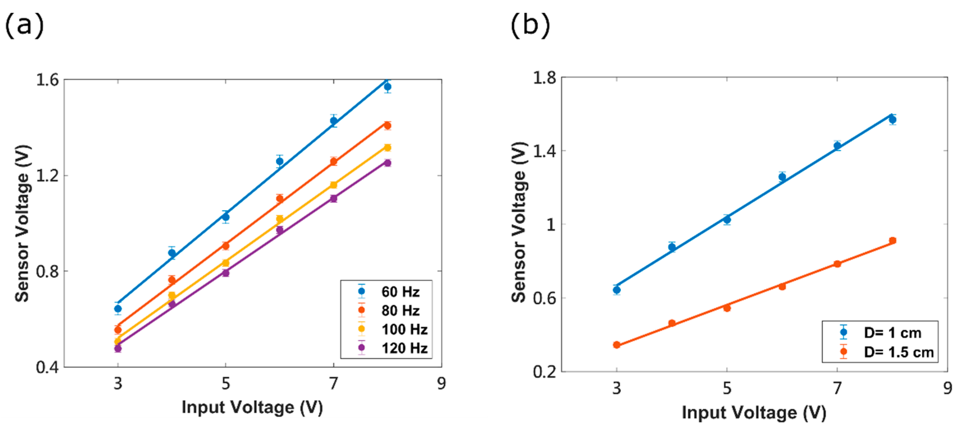
Figure 6a shows the measured sensor voltage versus input voltage to the solenoid at various frequencies. The output sensor voltage is linearly proportional to the input function generator voltage within the tuning range of the function generator, which indicates a linear relationship between the signals to the applied magnetic field is indeed valid within our experimental settings. In Figure 6b, measured sensor voltage versus input voltage at a distance of 1 and 1.5 cm to the solenoid are shown. It can be seen that a smaller sensor signal-input slope appears with a greater distance between the solenoid and the sensor structure. This could be explained by calculating the magnetic force between a solenoid and a magnet; the magnetic force would decrease monotonically with the increasing separation distance [22]. A solenoid-sensor distance less than 1 cm is not applicable in this experiment due to the deformed sensing hole structure at such distance, which also confirms the magnetic force explanation above.

4. Discussion

So far, various techniques have been developed for the FBG-based magnetic sensor, and each differs in measurement complexity, resolution, dynamic range, or sensitivity. Although typical laboratory AC magnetic sensors could achieve a sensitivity in the ~ nT / Hz range, such as SQUID sensors [10], their entire instruments and cooling system could occupy an entire room. In contrast, the compact size of the FBG-based sensor head offers advantages in applications such as medical surgery which demands for portability and convenience. The portability of FBG sensor also makes coalbed exploration a viable option. In addition, immunization to electromagnetic interference also give FBG sensor niches in environments where a high field is present, such as a transformer tower. Mainly, FBG is attached to a magnetic film, magnetic cantilever, or magnetic fluid [18,23,24,25,26], and is then coupled to the external magnetic field. Our work combines highly elastic polymer with a strong neodymium magnet into a compact magnetic sensing structure, which then exerts high strain to the sensing FBG in the presence of external magnetic field. As a result, our designed FBG magnetic sensor gives fine magnetic signal resolution yet achieves good magnetic sensitivity at DC to SLF. Table 1 summarizes different magnetic sensing FBG techniques.
To create high-elasticity polymer for a FBG sensor, fine experimental adjustment is required for a good recipe. In principle, a different mixture of load material and filler material variously alters the storage and loss modulus of the elastic polymer. For example, increasing the load material (i.e., resin) percentage might increase its composite storage modulus, but at the expanse of increasing its loss modulus [27]. A technical challenge for composite polymer mixing is to moderately increase its storage modulus without significantly increasing its loss modulus, so that the oscillatory motion of the polymer is not completely out of phase to the driving force at a frequency of interest. Therefore, the optimum recipe for the mixture percentage differs with the type and properties of both the filler and load material of the polymer composite, and it could not be predicted from simple calculation at a specific frequency beforehand. The elastic polymer’s performance is also expected to deteriorate from oxidation due to aging [28], and its durability over time remains a critical issue to overcome.
Throughout the work, the noise appears as errors in magnetic field readings, and it contributes to nearly ~1% of variation of the measurement at SLF. The geomagnetic field could possibly affect DC magnetic field sensing as a systematic error, but it does not contribute to AC magnetic field sensing at SLF due to modulation of signals. In principle, the noise can be attributed mainly to optical noise of the light source and mechanical noise from the fiber and polymer. With a stiffer fiber and with a more stable structure, the proposed FBG sensor might further reduce its noise in signals. By increasing signal integration time, the noise can be further reduced. There are also several technical improvements that could be implemented to get better sensitivity in the future. For example, the uniformity of soft polymer to surround the FBG could affect the measurement results due to the uneven sensing pressure converted to the stress in the FBG. Furthermore, the best elastic polymer material for the FBG sensor has not been optimized yet, and a better magnetic field to strain ratio might be achieved by simply replacing the current polymer. In addition, by incorporating a stronger magnetic film into the sensor structure, an enhanced magnet-to-stress converting ratio could also boost its sensitivity. It would also be of practical interest to test real SLF signals with a noisy background in the future, but this is beyond the scope of this work and is left for futuristic exploration.

5. Conclusions

We report a simple, FBG-based magnetic sensor that provides a linear measuring characteristic at super-low frequency. In addition, a DC magnetic sensitivity of 8.16   pm / G and a magnetic resolution of 3 G is experimentally obtained. The signal readings of the AC magnetic field sensor are consistent with the reading from a Gauss meter. Although many optic-based magnetic sensors are currently available, affordable manufacturing and portability are still key factors to develop a general-purpose sensor for wide applications. We expect that further improvements to this sensor will lead to even higher sensitivity. This includes further refinement of the sensing structure and more powerful magnet.

Author Contributions

Conceptualization, S.-Y.H.; methodology, C.-Y.L.; formal analysis, J.C.; investigation, J.C.; resources, W.-F.L.; data curation, J.C.; writing—original draft preparation, J.C.; writing—review and editing, J.C.; visualization, J.C.; supervision, W.-F.L.; project administration, W.-F.L.; funding acquisition, W.-F.L. All authors have read and agreed to the published version of the manuscript.

Funding

This research was funded by Ministry of Science and Technology, Taiwan, grant number MOST 108-2221-E-035 -075 -MY2 and MOST 109-2813-C-035-042-E.

Institutional Review Board Statement

Not applicable.

Informed Consent Statement

Not applicable.

Data Availability Statement

Not applicable.

Conflicts of Interest

The authors declare no conflict of interest.

References

  1. Savitz, D.A. Overview of Epidemiologic Research on Electric and Magnetic Fields and Cancer. Am. Ind. Hyg. Assoc. J. 1993, 54, 197–204. [Google Scholar] [CrossRef] [PubMed]
  2. Breysse, P.N.; Matanoski, G.M.; Elliott, E.A.; Francis, M.; Kaune, W.; Thomas, K. 60 Hertz Magnetic Field Exposure Assessment for an Investigation of Leukemia in Telephone Lineworkers. Am. J. Ind. Med. 1994, 26, 681–691. [Google Scholar] [CrossRef] [PubMed]
  3. Wang, N.; Zhao, S.; Hui, J.; Qin, Q. Passive Super-Low Frequency Electromagnetic Prospecting Technique. Front. Earth Sci. 2017, 11, 248–267. [Google Scholar] [CrossRef]
  4. Tumanski, S. Induction Coil Sensors—A Review. Meas. Sci. Technol. 2007, 18, R31–R46. [Google Scholar] [CrossRef]
  5. Tierney, T.M.; Holmes, N.; Mellor, S.; López, J.D.; Roberts, G.; Hill, R.M.; Boto, E.; Leggett, J.; Shah, V.; Brookes, M.J.; et al. Optically Pumped Magnetometers: From Quantum Origins to Multi-Channel Magnetoencephalography. NeuroImage 2019, 199, 598–608. [Google Scholar] [CrossRef]
  6. Sarreshtedari, F.; Mahboubian, F.; Sardari, M.H. Gradient Spin Echo Enhanced Proton Precession Magnetometer: A Novel System for Field Gradient Measurement. Rev. Sci. Instrum. 2020, 91, 075105. [Google Scholar] [CrossRef]
  7. Fagaly, R.L. Superconducting Quantum Interference Device Instruments and Applications. Rev. Sci. Instrum. 2006, 77, 101101. [Google Scholar] [CrossRef] [Green Version]
  8. Khan, M.A.; Sun, J.; Li, B.; Przybysz, A.; Kosel, J. Magnetic Sensors-A Review and Recent Technologies. Eng. Res. Express 2021, 3, 022005. [Google Scholar] [CrossRef]
  9. Willing, S.; Schlage, K.; Bocklage, L.; Ramin Moayed, M.M.; Gurieva, T.; Meier, G.; Röhlsberger, R. Novel Tunnel Magnetoresistive Sensor Functionalities via Oblique-Incidence Deposition. ACS Appl. Mater. Interfaces 2021, 13, 32343–32351. [Google Scholar] [CrossRef]
  10. Kirtley, J.R.; Ketchen, M.B.; Stawiasz, K.G.; Sun, J.Z.; Gallagher, W.J.; Blanton, S.H.; Wind, S.J. High-resolution Scanning SQUID Microscope. Appl. Phys. Lett. 1995, 66, 1138–1140. [Google Scholar] [CrossRef] [Green Version]
  11. Lenz, J.E. A Review of Magnetic Sensors. Proc. IEEE 1990, 78, 973–989. [Google Scholar] [CrossRef]
  12. Rao, Y.J. Recent Progress in Applications of In-fibre Bragg Grating Sensors. Opt. Lasers Eng. 1999, 31, 297–324. [Google Scholar] [CrossRef]
  13. Biazi, V.; Avellar, L.; Frizera, A.; Leal-Junior, A. Influence of Two-Plane Position and Stress on Intensity-Variation-Based Sensors: Towards Shape Sensing in Polymer Optical Fibers. Sensors 2021, 21, 7848. [Google Scholar] [CrossRef] [PubMed]
  14. Lazaro, R.; Frizera-Neto, A.; Marques, C.; Castellani, C.E.S.; Leal-Junior, A. FBG-Based Sensor for the Assessment of Heat Transfer Rate of Liquids in a Forced Convective Environment. Sensors 2021, 21, 6922. [Google Scholar] [CrossRef] [PubMed]
  15. Pereira, K.; Coimbra, W.; Lazaro, R.; Frizera-Neto, A.; Marques, C.; Leal-Junior, A.G. FBG-Based Temperature Sensors for Liquid Identification and Liquid Level Estimation via Random Forest. Sensors 2021, 21, 4568. [Google Scholar] [CrossRef] [PubMed]
  16. Leal-Junior, A.G.; Coimbra, W.; Marques, C.; Frizera, A. Highly Stretchable Polymer Optical Fiber for Mechanical Sensing in Artificial Tendons: Towards Novel Sensors for Soft Robotics. Actuators 2020, 9, 125. [Google Scholar] [CrossRef]
  17. Madhav, K.V.; Kumar, K.R.; Srinivas, T.; Asokan, S. Fiber Bragg Grating Magnetic Field Sensor. In Proceedings of the 2006 IEEE Instrumentation and Measurement Technology Conference Proceedings, Sorrento, Italy, 24–27 April 2006; pp. 2042–2044. [Google Scholar]
  18. He, J.; Yang, S.; Wei, Q. Intensity-Modulated Magnetic Field Sensor Based on Fiber Bragg Grating. AIP Adv. 2019, 9, 105303. [Google Scholar] [CrossRef]
  19. Sheng, H.-J.; Fu, M.-Y.; Chen, T.-C.; Liu, W.-F.; Bor, S.-S. A Lateral Pressure Sensor Using a Fiber Bragg Grating. IEEE Photonics Technol. Lett. 2004, 16, 1146–1148. [Google Scholar] [CrossRef]
  20. Rao, Y.-J. In-Fibre Bragg Grating Sensors. Meas. Sci. Technol. 1997, 8, 355–375. [Google Scholar] [CrossRef]
  21. Meyers, M.A.; Chawla, K.K. Mechanical Behavior of Materials, 2nd ed.; Cambridge University Press: Cambridge, UK, 2009; ISBN 978-0-521-86675-0. [Google Scholar]
  22. Kwon, M.; Jung, J.; Jang, T.; Sohn, S. Magnetic Forces between a Magnet and a Solenoid. Phys. Teach. 2020, 58, 330–334. [Google Scholar] [CrossRef]
  23. Quintero, S.; Braga, A.; Weber, H.; Bruno, A.; Araújo, J. A Magnetostrictive Composite-Fiber Bragg Grating Sensor. Sensors 2010, 10, 8119–8128. [Google Scholar] [CrossRef] [PubMed] [Green Version]
  24. Dai, Y.; Yang, M.; Xu, G.; Yuan, Y. Magnetic Field Sensor Based on Fiber Bragg Grating with a Spiral Microgroove Ablated by Femtosecond Laser. Opt. Express 2013, 21, 17386. [Google Scholar] [CrossRef] [PubMed]
  25. Liu, H.; Or, S.W.; Tam, H.Y. Magnetostrictive Composite–Fiber Bragg Grating (MC–FBG) Magnetic Field Sensor. Sens. Actuators Phys. 2012, 173, 122–126. [Google Scholar] [CrossRef]
  26. Chen, M.; Zhao, Y.; Lv, R.; Xia, F. Hybrid MEFPI/FBG Sensor for Simultaneous Measurement of Strain and Magnetic Field. Opt. Fiber Technol. 2017, 39, 32–36. [Google Scholar] [CrossRef]
  27. Zhang, C.; Li, H.; Zhuo, Z.; Dugnani, R.; Xue, W.; Zhou, Y.; Chen, Y.; Liu, H. Characterization of the Damping and Mechanical Properties of a Novel (ZnSnO3/PVDF)@PPy Nanofibers/EP Composite. RSC Adv. 2017, 7, 37130–37138. [Google Scholar] [CrossRef] [Green Version]
  28. Celina, M.C. Review of Polymer Oxidation and Its Relationship with Materials Performance and Lifetime Prediction. Polym. Degrad. Stab. 2013, 98, 2419–2429. [Google Scholar] [CrossRef]
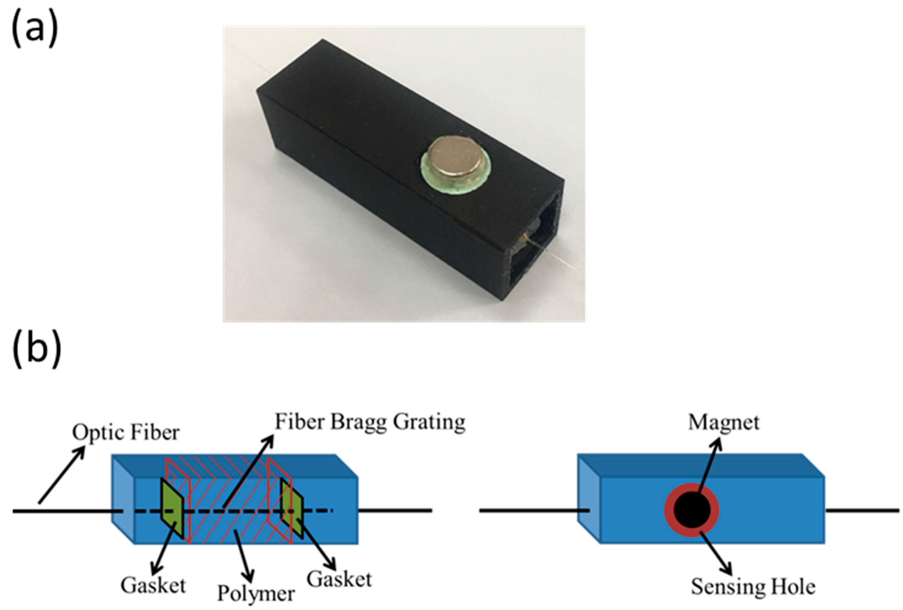
Figure 1. FBG AC magnetic sensor. (a) picture of the sensor; (b) the design structure of low-frequency magnetic field sensor.
Photonics 09 00102 g001
Figure 2. The experimental setup for measuring the low-frequency AC magnetic field. The numbers of the circulators indicate the ports and the direction of light.
Photonics 09 00102 g002
Figure 3. The reflection spectrum from both the SG and the MG. (a) The reflection spectrum at 25 °C (b) the reflection spectrum of FBG sensor when the MG was baked to 65 °C to match the peak from the SG.
Photonics 09 00102 g003
Figure 4. The experimental data for the DC magnetic-field measurement. The regression error is ~25 pm.
Photonics 09 00102 g004
Figure 5. Measured RMS signal voltage versus AC magnetic field frequency. The solid dots are the measured data, whereas the solid lines are fitted curves to the inverse function. (a) The voltage signals are plotted with various function generator input voltage from 5 to 8 V. The data were fitted with Equation (6) with an error ~5 mV. (b) The sensor voltage signals (left axis) as well as the magnetic field measured with a Gauss meter (right axis) are plotted at 50 to 130 Hz. The magnetic field was fitted with an inverse function similar to the voltage function with an error of 1 gauss.
Photonics 09 00102 g005
Figure 6. Measured RMS signal voltage versus function generator input RMS voltage. The solid dots are the measured data, whereas the solid lines are fitted linear function. (a) The RMS voltage signals versus RMS input voltage are plotted at 60, 80, 100, and 120 Hz. The largest linear regression error is ~27 mV. (b) The RMS voltage signals are plotted against RMS input voltage with a FBG to solenoid distance D of 1 and 1.5 cm. The linear regression error is ~15 mV.
Photonics 09 00102 g006
Table 1. Magnetic measurement comparison of some fiber grating sensor systems.
Sensitivity   η Magnetic Field ResolutionReferences
4 G
(3 G with 8.6 MPa pre-press)
[23]
19.1 G[18]
0.07 pm/G [24]
0.33 pm/G [25]
0.5 pm/G [26]
8.16 pm/G3 GThis work
Publisher’s Note: MDPI stays neutral with regard to jurisdictional claims in published maps and institutional affiliations.