Abstract
To study the radar cross-section (RCS) of a flapping-wing aircraft, a method of flapping-wing dynamic scattering is presented. The aircraft has two rigid wings and a fuselage similar to a bird’s body, where the plane shape of the wing is U-type. The aircraft model is established and the pitching and flapping actions of the wing are simulated. The electromagnetic scattering characteristics of aircraft under two flight modes, different radar wave frequencies and observation angles are investigated. The results show that in the given gliding mode, the fuselage provides the main contribution to the lateral peak value. For the given forward azimuth range in the flapping mode, increasing the azimuth can reduce the mean and peak of the aircraft dynamic RCS curve, while increasing the elevation angle will increase the peak and mean of the aircraft dynamic RCS curve. In the flapping mode, the mean RCS of the aircraft in the lateral backward azimuth is significantly lower than that in the lateral forward azimuth. For the given tail azimuth range, the increase of azimuth will increase the mean and peak level of aircraft dynamic RCS curve. The presented method is effective to study the dynamic RCS characteristics of the flapping-wing aircraft.
1. Introduction
Imitating birds in nature in shape, structure and flight principle, flapping wing aircraft can better hide or not be easily found when flying in the air. With thin wings and small fuselage, the overall level of radar cross-section (RCS) of flapping wing aircraft is low [1,2,3], while the change of RCS caused by wing flapping up and down has become a difficulty in the research of stealth performance of flapping wing aircraft.
The ideas used in the development of flapping wing aircraft include morphological bionics, structural bionics and functional bionics. Considering the dynamic similarity with insects on earth, flapping wing robots fly on Mars through bionic dynamics [4]. Based on the aerodynamic calculation method of flexible large deformation flapping wing, experiments under different flapping frequency, angle of attack and velocity are carried out in a low-speed wind tunnel [5]. The flapping wing aircraft has an X-shaped flapping wing configuration, a tail control surface for roll and pitch control, and a tail rotor for yaw control [6]. The plane shape of the wing of the flapping wing machine adopts a 1/4 elliptical contour, and the small motor installed on the fuselage forces the wings to flutter up and down [7]. Flapping wing unmanned aerial vehicle can fly silently at a low speed, and its application has become the focus of attention [8,9,10]. Flapping wing aircraft has the advantages of integrating lifting, hovering and propulsion functions [11], thus it can fly long distances with very little energy, while it has strong mobility and flexibility, and is more suitable for reconnaissance missions.
The scattering sources of flapping wing aircraft mainly come from the aircraft body and flapping wings. The geometric model of the blade is established, and the physical optics (PO) and the equivalent current method are used to calculate the RCS data, where the quasi-static principle (QSP) is used to simulate various movements of the target [12,13,14]. A complex target is divided into several triangular or quadrilateral surface elements to approximate the electromagnetic calculation model [15]. Remove a portion of the metal from the radiator and implement a periodic slot adjacent to the radiation edge. These slots reduce the vertical reflection of the radiator, which results in a reduction in the single station RCS [16]. The grid adjoint equation at each time step level is established, and then the adjoint variables of all time steps in a cycle are solved by time inverse integration [17]. The design of a low RCS millimeter-wave antenna array is presented to reduce the reflections toward the car fascia [18]. Control the timing of wing merging and separation to realize that the wing can complete two down pours and one up pours in one cycle [19]. Using the finite-element domain decomposition method, the statistical characteristics of bistatic RCS under horizontal and vertical polarization are obtained [20]. The multi-stage modeling method is adopted, and the wing is divided into inner wing and outer wing [21]. It can be seen that there are a wide range of factors affecting the RCS of flapping wing aircraft [22,23,24], such as flexible or rigid wing, observation angle [25,26,27], body configuration, radar wave frequency [28,29,30], polarization mode, wing pitch and flapping [31], and flight state. The body of the tilt rotor aircraft has adopted a preliminary stealth design, and the dynamic RCS of the rotor and the whole aircraft have been investigated and discussed under given electromagnetic wave conditions [32,33]. It could be seen that the dynamic electromagnetic scattering characteristics of a wide range of targets are worth exploring, including but not limited to flapping wing aircraft, helicopters, tilt rotor aircraft and warships.
As mentioned, flapping wing aircraft has strong mobility and low-speed flight ability, which is suitable for long range cruise and reconnaissance missions, while there are few studies on the stealth performance of flapping wing. In view of the complexity of flapping wing motion, it is a challenge to deal with the electromagnetic scattering characteristics of the whole flapping wing aircraft. Therefore, this paper attempts to establish a dynamic scattering method to solve the RCS of flapping wing aircraft, where the wing is set as a rigid body model, the aircraft fuselage refers to the body shape of birds, and the flapping and pitching actions of the wing are simulated. It is of engineering value to study the dynamic RCS of flapping wing aircraft.
2. Flapping-Wing Scattering Method
The schematic of the dynamic electromagnetic scattering of the U-type flapping wings aircraft is shown in Figure 1, where Af is the flapping angle of the wing, Ap represents the pitch angle of the wing, additional numerical subscripts are used to distinguish different wing numbers. α is the azimuth between the radar station and the flapping wings aircraft, β is the elevation between the radar station and the aircraft, frh represents radar wave frequency and horizontal polarization. Note that the wing model similar to the plane geometry of bird wings can refer to Figure A1 in Appendix A, and the relevant results can refer to Figure A1 and Figure A2.
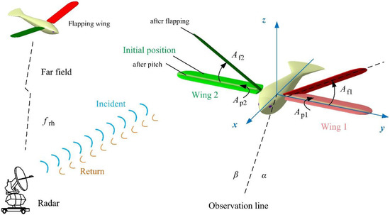
Figure 1.
Schematic of the dynamic electromagnetic scattering of the flapping-wing aircraft.
2.1. Flapping-Wing Motion
When the aircraft is flapping, the flapping angle is controlled in the following manner:
where t is time. The current flapping mode is recorded as mode M1, Ak, ωk, Bk and Ck are the coefficients of the model, additional numerical subscripts are used to distinguish different time periods. Tflap is the flapping period, noting that the initial flapping direction is upward.
For the second half cycle:
Consider the pitch angle of the wing:
where θup is the pitch angle of the wing when it flutters upward, θdown is the pitch angle of the wing when it flutters down.
When the flapping wing aircraft flies in glide mode, the pitch angle and flapping angle of the wing can be maintained at a fixed value:
where θ0 is a given pitch angle, θm is the boundary value of the pitch angle, φ0 is a given flapping angle, φm is the boundary value of the flapping angle. This glide mode is recorded as mode M0. Refer to Figure A1 for RCS results comparison of different wing shapes in the current mode.
2.2. Dynamic Electromagnetic Scattering
In the face of the same incident wave, the flapping of the wing causes the change of the position vector of any point on its surface, which leads to the change of the corresponding magnetic vector position:
where A(r) is the magnetic vector position generated by the surface induced current, μ is the permeability coefficient, Js is the induced current on the target surface, r′ is the coordinate vector of the source point, SI(t) is the illumination area on the target surface, r is the coordinate vector of the field point, k is the wave number in free space, dS is the integral facet, and R is the distance between the field point and the source point.
For the whole aircraft at any moment:
where M represents grid coordinate matrix, mflap is the model of the flapping wing aircraft, SD(t) is the dark area on the target surface.
The electric and magnetic fields could be calculated according to the magnetic vector position:
where ω is the electromagnetic wave angular frequency, R is the distance vector between the field point and the source point, and ε is the dielectric permittivity.
The surface of the flapping wing aircraft is discretized by triangular facets:
where Mflap is the grid coordinate matrix of the flapping wing aircraft, Mw1 is the grid coordinate matrix of the wing 1, Mw2 is the grid coordinate matrix of the wing 2, Mb is the grid coordinate matrix of the aircraft body.
For any facet (Fw1) on the surface of wing 1 when the wing starts pitching or flapping, the deflection effect of the facet on a given radar wave will change as shown in Figure 2, where Fb is the facet on the aircraft body.
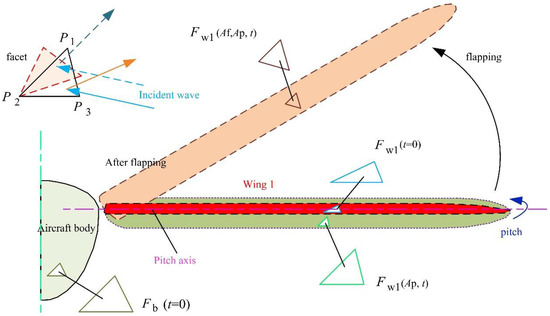
Figure 2.
Schematic diagram of the facets in lighting area when wing flapping.
For any vertex (Pi) on any facet of the wing 1, its coordinate information will continuously change as the wing pitches when treating the wing as a rigid body:
where Nf,w1 is the number of facets of the wing 1. Then consider the flapping of the wing:
Noting the relationship between the flapping axis of the wing and the xz plane:
where Yw1 is the distance from the flapping axis of the wing 1 to the xz plane. The flapping axis of the wing is parallel to the x axis and in the xy plane. The facet on the surface of wing 2 is treated similarly as above, thus the grid matrix of the whole flapping wing aircraft could be updated to:
Therefore, the illumination area (SI) on the surface of the flapping wing aircraft can be dynamically generated. When the fuselage is always fixed in the current coordinate system:
According to the assumption of physical optics method, no current is generated on the facet in the unlighted area:
where n is the unit normal vector of the outer direction of r’ at the target surface. Then the electric field formula can be transformed to the following form:
where λ is the wavelength in free space, k is the wave vector, r is the distance from the field point to the origin of coordinates. The integral term could be recorded as:
Then the dynamic RCS calculated by the physical optics method can be written as:
where σ is the radar cross-section, subscript F represents the facet contribution. In fact, the flapping wing aircraft has many edge features, including the edge of the tail, the leading edge and trailing edge of the wing. Therefore, the contribution of edge diffraction cannot be ignored, thus physical theory of diffraction (PTD) is used to calculate the RCS contribution of the edge:
where RCS subscript E represents the edge contribution. NF is the number of facets, NE is the number of edges. Tobs is the observation time boundary:
2.3. Method Validation
The verification of the presented calculation method is shown in Figure 3, where PO + MOM (method of moment)/MLFMM (multilayer fast multipole method) in FEKO is used to calculate the RCS curve of the target in a given state. QSP is used to generate the pitch angle and flapping angle of the wing in the given discrete state. It can be found that the two RCS curves are generally similar, including shape, peak and mean level, where the RCS mean of the presented calculation method is −18.3819 dBm2, that of the other curve is −17.9068 dBm2. When α = 0°, both RCS curves have peaks exceeding 4.279 dBm2, because the surface near the leading edge of the wing, the arc of the outer end of the wing and the lower surface of the wing all provide more scattering contributions.
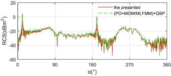
Figure 3.
Verification of the presented calculation method on the wing 1, frh = 7 GHz, t = 0.725 s, β = 0°, mode M1, Ak1 = Ck1 = π/10, ωk1 = ωk2= 3.1416 rad/s, Bk1 = Bk2 = −π/2, θup = −θdown = 20°, Ak2 = Ck2 = π/12.
Noting that at t = 0.725 s, the flapping angle of the wing 1 is 29.6901°, the pitch angle is 20°. When α = 191°, the RCS curve has the second largest peak, where the peak of the presented calculation method is 0.5644 dBm2, that of the other is 0.9483 dBm2. Other differences between the two curves are mainly reflected in local fluctuations. These results show that the presented calculation method is feasible to determine the RCS of the target.
3. Model of the Flapping-Wing Aircraft
The model of the flapping wing aircraft with two U-type wings is established as shown in Figure 4, where the wing 1 is marked red and wing 2 is marked green. Lb is the length of the aircraft body, Lt is the length of the aircraft tail, Lh is the length of the aircraft head, Hb is the height of the aircraft body. Wb is the width of the aircraft body, Wt is the width of the aircraft tail, Wtn is the minimum width of the fuselage tail. Airfoil 1 represents the airfoil used in the wing cross section. The aircraft model with bird wing shaped wings is built as shown in Figure A1.
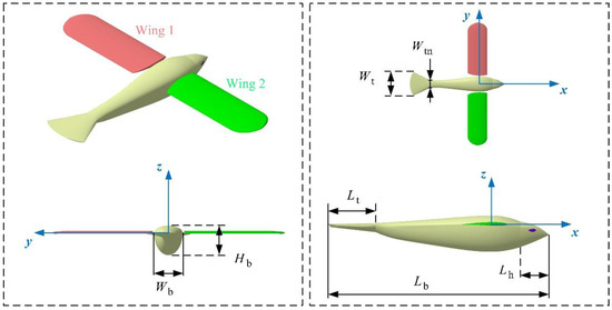
Figure 4.
Modeling of the flapping wing aircraft with two U-shaped wings.
The parameter values of the flapping wing aircraft are shown in Table 1, where the wing 1 and wing 2 use the same shape design parameters. The fuselage curve is streamlined, and the plane contour of the tail presents a sector. The flapping axis of the wing is parallel to the x-axis and attached to the side of the airframe. At the initial moment, the pitch angle and flapping angle of the wing are equal to 0, where the pitch axis of the wing coincides with the y-axis.

Table 1.
Parameter of the flapping wing aircraft.
The details of the U-type wing are shown in Figure 5, where the plane profile of the wing is U-shaped, and the wing root is cut by curve. Lw1 is the length of the wing, Yw1r represents the distance from the wing root to the xz plane. Yu1 and Yu2 represent the distance at different spanwise sections of the U-type wing, Cu1 and Cu2 represent the chord lengths at different sections of the U-arc wing. Cw1 represents the chord length of the straight section of the U-type wing, Xwle represents the distance from the leading edge to the yz plane when the wing is placed horizontally.
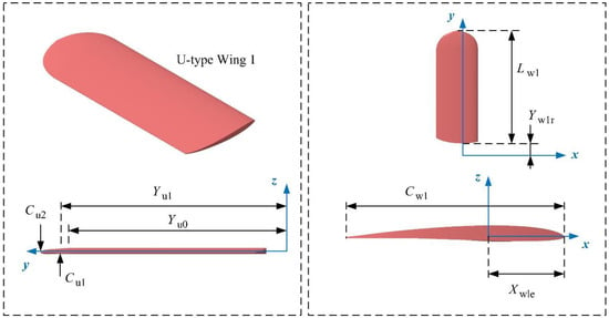
Figure 5.
Details of the U-type wing model.
The values of wing parameters are shown in Table 2, where the straight section wing occupies the main part of the wing. For the wing part of U-shaped arc segment, the airfoil adopts affine operation to control the change of chord length. For the whole wing, there is no preset twist angle for each section when it is at the initial time.

Table 2.
Parameter of the U-type wing.
The grid of the flapping wing aircraft is generated as shown in Figure 6, where high precision unstructured mesh technology is used to discretize the surface of the model. The grid of wing 1 is still marked red and the grid of wing 2 is marked green. For those regions with small size or large curvature change, the grid density increase technique is implemented, such as the leading edge of the wing, the narrow surface region near the trailing edge of the wing, the edge of the tail, and the edge line of the fuselage.
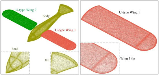
Figure 6.
Grid of the flapping wing aircraft.
The size distribution used for meshing is shown in Table 3, where the global minimum size is used to improve the mesh quality of the complex geometric features of the whole aircraft surface. For the connection between the straight section and U-arc section of the wing, the grid density increase technology is also adopted.

Table 3.
Grid size of the flapping wing aircraft.
4. Results and Discussion
4.1. Influence of Frequency
Figure 7 provides that the increase of radar wave frequency will have a wide impact on the RCS curve of the flapping wing aircraft at a given observation angle, including variation range, local fluctuation, mean and peak value. For the RCS at 3 GHz, the curve varies from −26.73 dBm2 to −14.6152 dBm2, where the RCS mean is −19.3432 dBm2 as in Table 4. The minimum of RCS curve at 5 GHz is –33.16 dBm2, that of the RCS curve at 7 GHz is −35.16 dBm2. As the frequency of the incident wave increases from 3 GHz to 7 GHz, the mean value of the RCS curve of the aircraft at the given observation azimuth increases first and then decreases. For the case at 9 GHz, the minimum value of RCS curve is –30.76 dBm2. With the increase of radar wave frequency to 13 GHz, the maximum of RCS curve increases, while the mean value first decreases and then increases. In addition, the minimum value of the RCS curve at 11 GHz and 13 GHz is less than −33.55 dBm2. These results show that the influence of incident wave frequency on the dynamic RCS curve of the aircraft is mainly reflected in the peak and fluctuation range at the given observation angle.
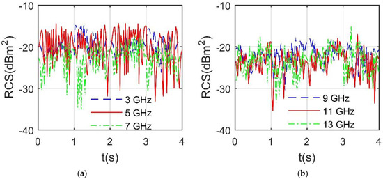
Figure 7.
RCS of the flapping wing aircraft, mode M1, Ak1 = Ck1 = π/10, ωk1 = ωk2 = 3.1416 rad/s, Bk1 = Bk2 = −π/2, θup = −θdown =20°, Ak2 = Ck2 = π/12, β = 0°, α = 29°. (a) RCS at 3, 5, 7 GHz. (b) RCS at 9, 11, 13 GHz.

Table 4.
RCS mean and peak of the flapping wing aircraft, mode M1, Ak1 = Ck1 = π/10, ωk1 = ωk2 = 3.1416 rad/s, Bk1 = Bk2 = −π/2, θup = −θdown = 20°, Ak2 = Ck2 = π/12, β = 0°, α = 29°, RCS unit: dBm2.
As shown in Figure 8a, the peak value of RCS curve at 2 GHz is higher than that of the other two curves, where the RCS curve at 2 GHz varies from −23.09 dBm2 to −9.224 dBm2. The maximum value of RCS curve at 4 GHz is −10.1355 dBm2, that of RCS curve at 6 GHz is −10.0856 dBm2. This shows that in the current observation angle and frequency range, with the increase of frequency, the mean value of RCS curve first decreases and then increases, while the peak value decreases continuously. Noting that the RCS mean at 4 GHz is −15.291 dBm2, that at 6 GHz is −14.6661 dBm2. For the RCS at 8 GHz as in Figure 8b, the mean RCS is −17.9824 dBm2, the peak is −12.3056 dBm2. As the frequency of the incident wave increases to 12 GHz, the mean and peak of the RCS curve at that observation angle increase gradually, where the mean of the RCS curve at 10 GHz is −16.8794 dBm2, that of the RCS curve at 12 GHz is −16.1253 dBm2. When the radar wave frequency is 12 GHz, the maximum value of RCS curve reaches −11.3846 dBm2 and the minimum is −30.4 dBm2. In addition, the shape and fluctuation of RCS curve change with the increase of frequency. These results show that under the current observation conditions, the increase of incident wave frequency will change the mean and peak level of RCS curve.
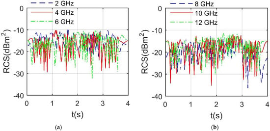
Figure 8.
RCS of the flapping wing aircraft, mode M1, Ak1 = Ck1= π/10, ωk1 = ωk2= 3.1416 rad/s, Bk1 = Bk2 = −π/2, θup = −θdown = 20°, Ak2 = Ck2 = π/12, β = 10°, α = 50°. (a) RCS at 2, 4, 6 GHz. (b) RCS at 8, 10, 12 GHz.
Figure 9 indicates that in the given M0 mode, the peak value of the RCS curve of the aircraft increases with the increase of the incident wave frequency. For the case of 2 GHz, the mean RCS of the curve is −0.5689 dBm2, the peak is 14.5160 dBm2. When the incident wave frequency is 4 GHz, the mean value of RCS curve is equal to −0.9103 dBm2 and the peak value is 15.4347 dBm2. As the frequency increases to 4 GHz, the mean value of RCS curve further decreases to −1.2130 dBm2 and the peak value increases to 15.7452 dBm2. For a single RCS curve, two larger peaks can be found at azimuth angles equal to 96.25° and 264.5°, because at this time, the side surface of the aircraft body provides the main scattering contribution, and the outer end arc of the U-wing provides some scattering contribution. As the frequency further increases to 12 GHz, the mean value of RCS curve further decreases to −2.3674 dBm2, and the peak value gradually increases to 17.5255 dBm2. In the current mode, the flapping wing aircraft remains in the gliding attitude, and the pitch angle and flapping angle of the wing remain unchanged. These results show that in the given M0 mode, the peak level of RCS curve increases gradually with the increase of incident wave frequency.
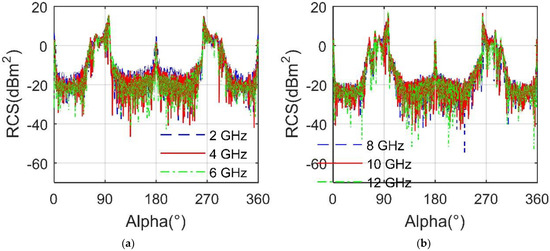
Figure 9.
RCS of the flapping wing aircraft, mode M0, θ0 = 5°, φ0 = 10°, β = 0°. (a) RCS at 2, 4, 6 GHz. (b) RCS at 8, 10, 12 GHz.
4.2. Forward RCS Analysis
Figure 10 shows that in the given M1 mode, the RCS curve of the aircraft is obviously different under different forward azimuth. When α = 0°, the electromagnetic wave is incident in the negative direction along the x-axis, thus the leading edge of the wing and its adjacent surfaces are in the irradiation area.
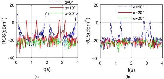
Figure 10.
Forward RCS of the flapping wing aircraft, mode M1, Ak1 = Ck1 = π/10, ωk1 = ωk2= 3.1416 rad/s, Bk1 = Bk2 = −π/2, θup = −θdown = 20°, Ak2 = Ck2 = π/12, β = 0°, frh = 7 GHz. (a) RCS at α = 0°, 10°, 20°. (b) RCS at α = 10°, 20°, 30°.
With the wing pitching and flapping up and down, the RCS curve at 0° azimuth shows a trend of first decreasing, then increasing, then decreasing and then increasing with local fluctuations. The mean RCS of α = 0° curve is 1.3571 dBm2, the peak reaches 11.56 dBm2. As the azimuth increases to 10°, the mean level of RCS curve decreases rapidly to −9.6056 dBm2, where the peak decreases to 2.9475 dBm2. At this time, the RCS curve shows four large peaks and some small local fluctuations. When α = 20°, the mean RCS of the curve is as low as −21.5189 dBm2, and the peak value is reduced to −16.4791 dBm2. As the azimuth angle further increases to 30°, the mean value of RCS curve decreases to −21.8629 dBm2 and the peak decreases to −16.4729 dBm2. The peaks of RCS curves at 0° and 10° azimuth are significantly higher than those of the remaining two curves. As the azimuth increases from 0° to 30°, the peak value, mean value and fluctuation range of RCS curve decrease significantly. These results show that the mean and peak value of the forward RCS curve of the flapping wing aircraft will be lower at a large forward azimuth.
Figure 11 shows that under the given M1 mode, the electromagnetic scattering characteristics of the wing surface change obviously with the flapping of the wing. For the case at α = 10° and t = 0.5 s, the flapping angle of the wing 1 is 18°, where the pitch angle of the wing is 20°. Because the electromagnetic wave is incident from the front and bottom direction of the wing, the leading edge of the wing presents a small number of yellow areas. The upper surface of the wing and the top area of the tail are dark blue, where a small amount of yellow and orange inclusions is distributed on the side of the body. There are many orange-red areas in the head of the body, and some edge and transition areas are yellow. The lower surface of wing 1 is orange red, while the lower surface of wing 2 is orange. For the case at α = 20° and t = 2.8 s, the flapping angle of the wing 1 is 27.1353°, the pitch angle of the wing is −20°. Since the absolute value of the pitch angle of the wing is greater than the elevation angle, all the upper surfaces of the wing 1 are illuminated. In addition to the effect of increasing azimuth, the leading edge of the upper surface of wing 2 and its adjacent half of the upper surface are illuminated. The dark blue area on the top of the body is enlarged, and the color depth of the red area on the side of the nose is slightly deepened. Since the wing is flapping downward, the scattering characteristics of the upper surface of wing 1 are strong. From the leading edge of wing 1 to the middle of wing 1, it presents an orange to yellow gradient. These results show that flapping wings will bring changing strong scattering sources to the flapping aircraft.
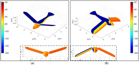
Figure 11.
Surface scattering characteristics of the aircraft, mode M1, Ak1 = Ck1 = π/10, ωk1 = ωk2 = 3.1416 rad/s, Bk1 = Bk2 = −π/2, θup = −θdown = 20°, Ak2 = Ck2 = π/12, β = −5°, frh = 7 GHz, RCS unit; dBm2. (a) Case at α = 10°, t = 0.5 s. (b) Case at α = 20°, t = 2.8 s.
As shown in Figure 12, the increase of elevation angle will have a significant impact on the RCS~azimuth curve of the flapping wing aircraft. For the RCS at α = 0°, the RCS curve with β = 20° is significantly different from the other two RCS curves, including shape and peak value. Within 0 to 1 s, the RCS curve with β = 20° fluctuates slightly near 9.813 dBm2, and the fluctuation here is displayed as a straight line within the current observation range. Because the elevation angle is equal to the pitch angle of the wing, the leading edge of the wing is the irradiation area, and the scattering level of the upper and lower surfaces of the wing is low. From 1 to 3 s, the wing starts to flap downward, while the pitch angle of the wing remains −20°, making the upper surface of the wing a dynamic strong scattering source. The peak of the RCS curve at β = 20° is 14.16 dBm2, that of the RCS curve at β = 10° is 10.91 dBm2. The mean value of RCS curve with β = 20° reaches 7.6523 dBm2, which makes the current observation conditions unfavorable for the stealth flight of the aircraft. For the RCS at α = 20°, as the elevation angle increases from 0° to 20°, the mean of RCS curve increases from −21.5189 dBm2 to −7.8321 dBm2. The RCS curve with β = 10° has a peak greater than 4.98 dBm2, while the RCS curve with β = 20° has two peaks greater than 9.46 dBm2. These results show that under the forward azimuth, the increase of elevation angle will significantly change the dynamic RCS characteristics of the flapping wing aircraft, and increase the mean and peak levels.
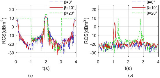
Figure 12.
RCS of the flapping wing aircraft, mode M1, Ak1 = Ck1 = π/10, ωk1 = ωk2 = 3.1416 rad/s, Bk1 = Bk2 = −π/2, θup = −θdown = 20°, Ak2 = Ck2 = π/12, frh = 7 GHz. (a) RCS at α = 0°. (b) RCS at α = 20°.
4.3. Side RCS Analysis
Figure 13 investigates that the mean value of RCS curve of the aircraft is different under different lateral azimuth. As the azimuth increases from 40° to 60°, the mean value of the RCS curve increases from −20.6414 dBm2 to −5.9584 dBm2, the peak increases from −16.59 dBm2 to −3.3 dBm2. When α = 50°, the mean of the RCS curve is −16.7467 dBm2, where the fluctuation range is from −31.13 dBm2 to −12.3466 dBm2. As the azimuth increases from 60° to 80°, the mean and peak values of RCS curves first decrease and then increase. When α=80°, the mean value of the RCS curve is 2.1729 dBm2, where the peak is 4.0392 dBm2. In view of the increasing azimuth, the scattering contribution of the body side of the flapping wing aircraft gradually increases, which improves the mean level of the RCS curve. At the same time, the contribution of the dynamic scattering characteristics of the outer camber of the U-wing increases gradually, while the contribution of the leading edge of the wing decreases gradually.
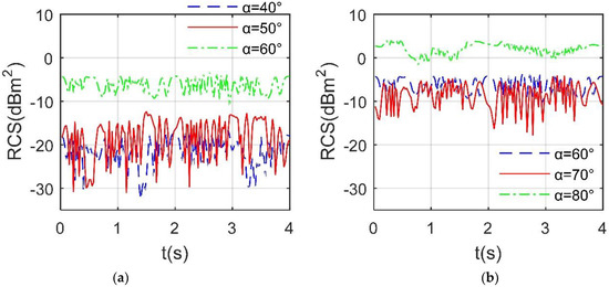
Figure 13.
Side RCS of the flapping wing aircraft, mode M1, Ak1 = Ck1=π/10, ωk1 = ωk2 = 3.1416 rad/s, Bk1 = Bk2 = −π/2, θup = −θdown = 20°, Ak2 = Ck2 = π/12, β = 0°, frh = 7 GHz. (a) RCS at α = 40°, 50°, 60°. (b) RCS at α = 60°, 70°, 80°.
As presented in Figure 14a, the shapes and peaks of the three RCS curves are different, where the peak of the curve at α = 100° is −6.4955 dBm2, that of the curve at α = 120° is −17.6693 dBm2. The mean value and fluctuation range of the two RCS curves with α = 100° and α = 110° are similar, where the mean of the former curve is −9.5172 dBm2, that of the later curve is −11.7566 dBm2. As the azimuth increases from 100° to 120°, the mean and peak of RCS curve show a decreasing trend, because the trailing edge of the wing and its adjacent surface become the main dynamic scattering source. Note that the trailing edge of the wing has thinner geometric features than the leading edge and outer end, resulting in lower scattering contribution. For the Figure 14b, it can be seen that the fluctuation ranges of the three RCS curves are similar. As the azimuth increases from 130° to 150°, the mean and peak value of RCS curve first increases and then decreases, where the mean of the curve at α = 130° is −23.0354 dBm2, that of the curve at α = 150° is −21.8895 dBm2. These results show that for the lateral backward azimuth, the mean value of the dynamic RCS curve of the flapping wing aircraft generally decreases with the approach of the incident wave to the tail.
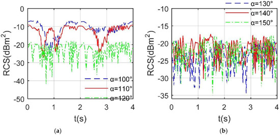
Figure 14.
Side RCS of the flapping wing aircraft, mode M1, Ak1 = Ck1=π/10, ωk1 = ωk2 = 3.1416 rad/s, Bk1 = Bk2 = −π/2, θup = −θdown = 20°, Ak2 = Ck2 = π/12, frh = 7 GHz, β = 0°. (a) RCS at α = 100°, 110°, 120°. (b) RCS at α = 130°, 140°, 150°.
4.4. Tail RCS Analysis
Figure 15 reveals that with the increase of azimuth, the peak level of RCS curve of flapping wing aircraft increases. For the RCS at β = 0°, the mean of the RCS curve at α = 160° is −21.4583 dBm2, that of the curve at α = 170° is −12.4488 dBm2. As the azimuth increases to 180°, the mean value of RCS curve is increased to −3.3248 dBm2 and the peak value is increased to 6.1166 dBm2, because at this time, the trailing edge of the wing and its adjacent areas provide more dynamic scattering contributions, and the surface and edge of the aircraft tail provide more static scattering contributions. Compared with the forward RCS curve, the shape of the RCS curve at 180° azimuth is similar to that at 0° azimuth, while the peak and mean are lower. For the RCS at α = 160°, the RCS curves at different elevation angles have obvious differences in peak value and fluctuation range. As the elevation angle increases from 0° to 20°, the mean value of RCS curve increases from −21.4583 dBm2 to −15.9451 dBm2, where the peak value increases from −17.0297 dBm2 to 0.1886 dBm2. At a large elevation angle, the U-shaped camber, trailing edge and upper surface of the wing can provide dynamic scattering sources. These results show that the peak value and mean value of the aircraft RCS curve increase with the increase of azimuth within a given range of tail azimuth.
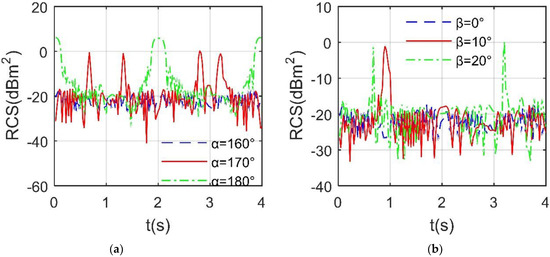
Figure 15.
Tail RCS of the flapping wing aircraft, mode M1, Ak1 = Ck1 = π/10, ωk1 = ωk2 = 3.1416 rad/s, Bk1 = Bk2 = −π/2, θup = −θdown = 20°, Ak2 = Ck2 = π/12, frh = 7 GHz. (a) RCS at β = 0°. (b) RCS at α = 160°.
As shown in Figure 16a, under the given observation azimuth, the peak levels of the three RCS curves are similar. The mean RCS of the curve at β = 0° is −12.4488 dBm2, that of the curve at β = 10° is −15.939 dBm2. As the elevation angle increases from 0° to 20°, the peak of RCS curve decreases from 0.2447 dBm2 to −2.0169 dBm2, and the mean value decreases from −12.4488 dBm2 to −17.0115 dBm2. In addition, the RCS curve with β = 0° has four large peaks, while the other two curves have two large peaks. For the Figure 16b, it can be found that the shape of RCS curve changes greatly when β = 20°. Although the peaks of the three RCS curves are around 6.25 dBm2, their mean values are different. The mean of the RCS curve at β = 0° is −3.3248 dBm2, that of the curve at β = 10° is −2.8461 dBm2, where the fluctuation range and trend of the two RCS curves are similar. When β = 20°, the RCS curve has a wide range of values higher than 1.025 dBm2 in the middle period, because at this time, the two U-shaped wings are flapping downward, and the trailing edge of the wing has been providing a large scattering contribution. These results show that in the positive tail direction (α = 180°), the increase of lift angle is unfavorable to the peak and mean of the dynamic RCS curve of the flapping wing aircraft.
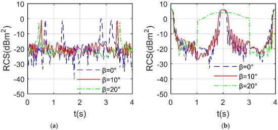
Figure 16.
Tail RCS of the flapping wing aircraft, mode M1, Ak1 = Ck1 = π/10, ωk1 = ωk2 = 3.1416 rad/s, Bk1 = Bk2 = −π/2, θup = −θdown = 20°, Ak2 = Ck2 = π/12, frh = 7 GHz. (a) RCS at α = 170°. (b) RCS at α = 180°.
5. Conclusions
Based on the established dynamic scattering method, the electromagnetic scattering characteristics of the U-type flapping wing aircraft are studied. Through the analysis and discussion, this paper can draw the following conclusions:
- (1)
- In the given gliding mode, the peak of the RCS curve of the aircraft increases with the increase of the radar wave frequency while the fuselage provides more contribution to lateral RCS peak. In the given flapping mode, the frequency mainly affects the local fluctuation of the aircraft dynamic RCS curve.
- (2)
- For the given forward azimuth range in flapping mode, increasing the azimuth can reduce the mean and peak levels of the aircraft dynamic RCS curve, while increasing the elevation angle will increase the peak and mean levels of the aircraft dynamic RCS curve.
- (3)
- In the flapping mode, the mean of the dynamic RCS curve of the aircraft in the lateral backward azimuth is significantly lower than that in the lateral forward azimuth. For the given tail azimuth range, the increase of azimuth will increase the mean and peak of aircraft dynamic RCS curve.
Future outlook: two segment wing, multi segment wing and elastic wing will be the focus of research. Practical flapping control law and attitude change also need more attention.
Author Contributions
Conceptualization, Z.Z. and J.H.; methodology and validation, Z.Z.; formal analysis, investigation, Z.Z. and J.H.; writing—original draft preparation, Z.Z.; writing—review and editing, Z.Z. and J.H.; visualization, funding acquisition, Z.Z. All authors have read and agreed to the published version of the manuscript.
Funding
This research was supported by the project funded by China Postdoctoral Science Foundation (Grant Nos. BX20200035, 2020M680005).
Institutional Review Board Statement
Not applicable.
Informed Consent Statement
Not applicable.
Data Availability Statement
Not applicable.
Acknowledgments
Thanks to Jun Huang for his guidance on the study work of this paper.
Conflicts of Interest
The authors declare no conflict of interest.
Appendix A. Wing Shape and Multiple Scattering
A flapping wing aircraft model with reference to the shape of bird wings has been established as shown in Figure A1, where Mf1 represents the aircraft with U-shaped wings, and Mf2 represents the aircraft with plane shape of bird wing, noting that the airfoil and fuselage of these two types of aircraft are the same, and the Mf2 wingspan is 5.296 m. The RCS mean of Mf1 curve is −2.5477 dBm2, that of Mf2 curve is −3.1651 dBm2, showing that although there are small differences in the shape and span of wings, the average RCS levels of these two types of aircraft are close. The peak of Mf1 curve is 14.15 dBm2 appearing at 97° azimuth, that of Mf2 curve is 15.31 dBm2 at 97° azimuth, indicating that the peak levels of these two aircraft are similar. These results show that the RCS of these two aircraft with different wing shapes are similar in mean level and peak value, and the main difference is reflected in local maximum value and local fluctuation.
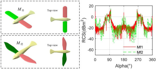
Figure A1.
Comparison of different wing shapes, mode M0, θ0 = 0°, φ0 = 0°, β = 2°, frh = 7 GHz.
For electromagnetic waves under certain incident conditions, there may be secondary or multiple reflections on the target surface:
where J means the surface current, and the subscript means the scattering number. G is the Green function of free space:
Considering the current under irradiation, its expression can be updated to:
The RCS of Mf2 aircraft considering multiple scattering is shown in Figure A2, where Nms is the number of times of multiple scattering. The average RCS of Nms = 1 curve is −2.0732 dBm2, where the maximum is 13.87 dBm2 occurring at 96° azimuth. Under the current observation conditions, the mean RCS of the Nms = 2 curve is equal to −2.0732 dBm2, where the peak size and position remain unchanged, because the surface of this target adopts a concise shape design, which has a good deflection effect on the current incident wave. This performance can also be reflected in the remaining two curves. If it is necessary to obtain the obvious difference caused by multiple scattering, it is feasible to adjust the appropriate incidence angle.
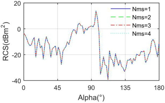
Figure A2.
RCS of Mf2 aircraft considering multiple scattering, mode M0, θ0 = 0°, φ0 = 0°, β = 0°, frh = 3 GHz.
References
- Shen, H.; Yu, Y. Development and key technologies of morphological bionic aircraft. Adv. Aeronaut. Sci. Eng. 2021, 12, 9–19. [Google Scholar]
- Bian, Z.; Li, J.; Guo, L.; Luo, X. Analyzing the Electromagnetic Scattering Characteristics of a Hypersonic Vehicle Based on the Inhomogeneity Zonal Medium Model. IEEE Trans. Antennas Propag. 2021, 69, 971–988. [Google Scholar] [CrossRef]
- Wu, J.; Li, Z. Study on the aerodynamic forces of flapping wing MAV eith PVDF sensor. Piezoelectrics Acoustooptics 2012, 34, 712–715. [Google Scholar]
- Bluman, J.E.; Pohly, J.A.; Sridhar, M.K.; Kang, C.K.; Landrum, D.B.; Fahimi, F.; Aono, H. Achieving bioinspired flapping wing hovering flight solutions on Mars via wing scaling. Bioinspiration Biomim. 2018, 13, 046010. [Google Scholar] [CrossRef]
- Ang, H.; Zeng, R.; Duan, W.; Shi, Z. Aerodynamic experimental investigation for mechanism of lift and thrust of flexible flapping-wing MAV. J. Aerosp. Power 2007, 22, 1837–1844. [Google Scholar]
- Jiao, Z.; Wang, L.; Zhao, L.; Jiang, W. Hover flight control of X-shaped flapping wing aircraft considering wing–tail interactions. Aerosp. Sci. Technol. 2021, 116, 106870. [Google Scholar] [CrossRef]
- Cui, X.; Wei, R.; Zhou, X.; Shao, M.; Huang, J. Aerodynamic computation of flapping-wing simulation bird wings. J. Syst. Simul. 2009, 21, 4995–4998. [Google Scholar]
- Gueddida, A.; Djafari Rouhani, B.; Pennec, Y.; Di Donato, A.; Pierantoni, L.; Korovin, A.; Mencarelli, D. Coupling of Integrated Waveguide and Optomechanic Cavity for Microwave Phonon Excitation in Si Nanobeams. Photonics 2020, 7, 67. [Google Scholar] [CrossRef]
- Zhang, Y.; Song, W.; Song, B.; Zhang, W. Research on wing structure deformation for aerodynamic force and inertial force of flapping-wing. J. Aerosp. Power 2010, 25, 1561–1566. [Google Scholar]
- Abbasi, S.H.; Mahmood, A.; Khaliq, A. Bioinspired Feathered Flapping Wing UAV Design for Operation in Gusty Environment. J. Robot. 2021, 2021, 8923599. [Google Scholar] [CrossRef]
- Bao, F.; Yang, Q.; He, Y. Experimental investigation on shedding vortex and lift mechanism of flapping wing model single degree of freedom. J. Aerosp. Power 2014, 29, 1092–1099. [Google Scholar]
- Zhou, Z.; Huang, J. Dynamic Scattering Approach for Solving the Radar Cross-Section of the Warship under Complex Motion Conditions. Photonics 2020, 7, 64. [Google Scholar] [CrossRef]
- Ye, S.; Xiong, J. Dynamic RCS behavior of helicopter rotating blades. Acta Aeronaut. Astronaut. Sin. 2006, 27, 816–822. [Google Scholar]
- Wong, S.K.; Riseborough, E.; Duff, G.; Chan, K.K. Radar cross-section measurements of a full-scale aircraft duct/engine structure. IEEE Trans. Antennas Propag. 2006, 54, 2436–2441. [Google Scholar] [CrossRef]
- Jiang, Z.H. Research on Radar Target Characteristics of Unmanned Helicopter. J. Astronaut. Metrol. Meas. 2015, 35, 61–66. [Google Scholar]
- Rajesh, N.; Malathi, K.; Raju, S.; Kumar, V.A.; Prasath, S.D.R.; Alsath, M.G.N. Design of Vivaldi antenna with wideband radar cross section reduction. IEEE Trans. Antennas Propag. 2017, 65, 2102–2105. [Google Scholar] [CrossRef]
- Xiao, T.; Luo, D.; Zheng, X.; Ang, H.; Ji, A. Progress and chanllenges in unsteady aerodynamic optimization design of bionic flapping-wings. Acta Aerodyn. Sin. 2018, 36, 80–87. [Google Scholar]
- Vasanelli, C.; Bögelsack, F.; Waldschmidt, C. Reducing the radar cross section of microstrip arrays using AMC structures for the vehicle integration of automotive radars. IEEE Trans. Antennas Propag. 2018, 66, 1456–1464. [Google Scholar] [CrossRef]
- Yang, Y.; Lu, G. Simulation research on aerodynamic performance of counterbeat four-wing flapping wing aircraft. Flight Dyn. 2019, 37, 25–29. [Google Scholar]
- Ozgun, O.; Kuzuoglu, M. A domain decomposition finite-element method for modeling electromagnetic scattering from rough sea surfaces with emphasis on near-forward scattering. IEEE Trans. Antennas Propag. 2018, 67, 335–345. [Google Scholar] [CrossRef]
- Yang, Y.; Gu, X. Simulation Study on Aerodynamic Characteristics of Flapping-wing Aircraft with Multi-stage Wing and Multiple Degree of Freedom. J. Syst. Simul. 2019, 31, 2019. [Google Scholar]
- Deck-Léger, Z.-L.; Zheng, X.; Caloz, C. Electromagnetic Wave Scattering from a Moving Medium with Stationary Interface across the Interluminal Regime. Photonics 2021, 8, 202. [Google Scholar] [CrossRef]
- Guo, J.; Yin, H.C.; Ye, S.J.; Man, L.; Jia, Q. Novel technology for electromagnetic characteristic simulation of helicopter blades. Acta Aeronaut. Et Astronaut. Sin. 2019, 40, 322732. [Google Scholar]
- Wang, C.; Li, Y.; Feng, M.; Wang, J.; Ma, H.; Zhang, J.; Qu, S. Frequency-selective structure with transmission and scattering deflection based on spoof surface plasmon polariton modes. IEEE Trans. Antennas Propag. 2019, 67, 6508–6514. [Google Scholar] [CrossRef]
- Zhou, Z.; Huang, J. Study of RCS characteristics of tilt-rotor aircraft based on dynamic calculation approach. Chin. J. Aeronaut. 2022, 35, 426–437. [Google Scholar] [CrossRef]
- Fu, Y.; Zhao, S. Design of the aircraft model for bionic dragonflies’flapping wings and analysis on the aerodynamic characteristics. J. Mach. Des. 2021, 38, 10, 79–87. [Google Scholar]
- Wang, X.Y.; Dallmann, T.; Moch, R.; Heberling, D. ISAR tomography for full-polarimetric 3-D radar cross-section measurements. IEEE Trans. Antennas Propag. 2019, 67, 2853–2858. [Google Scholar] [CrossRef]
- Zhou, Z.; Huang, J.; Wang, J. Compound helicopter multi-rotor dynamic radar cross section response analysis. Aerosp. Sci. Technol. 2020, 105, 106047. [Google Scholar] [CrossRef]
- Peng, C.; Sun, L.; Wang, Y.; Tan, W.; Xiao, F. Control oriented longitudinal modeling and analysis of pigeon-like flapping-wing aircraft. J. Beijing Univ. Aeronaut. Astronaut. 2021. [CrossRef]
- Viet, H.; Lee, C.; Lee, J. Two-dimensional efficient broadband retrodirective metasurface. IEEE Trans. Antennas Propag. 2019, 68, 2451–2456. [Google Scholar]
- Elbaz, A.; He, Z.; Gao, B.; Chi, J.; Su, E.; Zhang, D.; Liu, S.; Xu, H.; Liu, H.; Gu, Z. Design of a two-stage flapping wing bionic aircraft. Electromechanical Eng. Technol. 2021, 50, 9–12. [Google Scholar]
- Zhou, Z.; Huang, J.; Chen, C.; Zhang, J. Keen Investigation of the Electromagnetic Scattering Characteristics of Tiltrotor Aircraft Based on Dynamic Calculation Method. Photonics 2021, 8, 175. [Google Scholar] [CrossRef]
- Wang, Q.; Zhang, X.; Yan, X.; Wang, F.; Cheng, T. Design of a Surface Plasmon Resonance Temperature Sensor with Multi-Wavebands Based on Conjoined-Tubular Anti-Resonance Fiber. Photonics 2021, 8, 231. [Google Scholar] [CrossRef]
Publisher’s Note: MDPI stays neutral with regard to jurisdictional claims in published maps and institutional affiliations. |
© 2022 by the authors. Licensee MDPI, Basel, Switzerland. This article is an open access article distributed under the terms and conditions of the Creative Commons Attribution (CC BY) license (https://creativecommons.org/licenses/by/4.0/).