Abstract
In this research, we present and design a blended wavelength-division-multiplexing passive optical network (WDM-PON) architecture to deliver both baseband and free-space optical (FSO) signals by using two wavelength bands over an available bandwidth to avoid the signal interference. Only using few additional components in the optical line termination (OLT) and optical network unit (ONU)/optical wireless unit (OWU) can achieve self-protected operation in the presented hybrid fiber-FSO access network against fiber breakage. In the measurement, eight WDM wavelengths with 24.3 Gbit/s on-off keying (OOK) modulation format are applied to verify and discuss the bit error rate (BER) performances of baseband and FSO signals, respectively, through 25 km fiber and 2 m wireless FSO connections. Therefore, the presented PON not only can deliver both baseband and FSO traffics, but can also provide a self-restored mechanism against fiber fault.
1. Introduction
Currently, because of the massive expansion of artificial intelligence (AI) in applications such as big data, data centers, 3D and 4K/8K video, and online gaming, the capacity requirement is growing rapidly in the last mile access network [1,2]. To provide huge bandwidth for end users, the passive optical network (PON) will be a capable solution [3,4]. As we know, the wavelength division multiplexing (WDM) technique can be applied in such a PON network to offer 1.25 to 40 Gbit/s traffic rate or even up to 100 Gbit/s for individual subscribers via point-to-point (PtP) access with security characteristic [5,6,7]. To achieve wide data capacity, the modulation format of on-off keying (OOK) or pulse-amplitude modulation (PAM) is the most common way, using intensity modulation direct detection (IM/DD) [8,9].
To support the flexible and reliable fiber-wireless seamless network access, WDM FSO-related technologies have been proposed and integrated into the PON system [10,11]. Moreover, because of some special environmental and geographical restrictions, it is impossible to deploy fiber-based access network for data connection [12,13]. Thus, the FSO-based data signal would be a valuable method to integrate into a fiber network to solve this issue [13,14,15,16,17]. Utilizing the same WDM wavelength for downstream and upstream transmission will induce the Rayleigh backscattering (RB) beat noise to interfere with the signal transmission performance. To clear up the RB noise in a fiber WDM-PON network, uses of differential phase-shift keying (DPSK) modulation [18], the Mach–Zehnder delay interferometer (MZDI) method [19], in-band optical filtering influence [20], and alternative routing path [21] have been demonstrated experimentally. As a result, to provide the WDM baseband and FSO traffics simultaneously in such a PON system, several related studies have been also proposed via the hybrid fiber-FSO access network, together with RB mitigation [22]. In addition, once a fiber breakage has occurred in the feeder or distribution fiber of a PON system, it will damage the bidirectional baseband and FSO signal transmissions between the optical line termination (OLT) and optical network unit (ONU)/optical wireless network (OWU) [23,24,25,26]. The fiber breakage on PON access is a very important issue for data connection, especially in high-speed and high-capacity baseband or FSO signal transmissions. To evade this problem, employing the alternative fiber connections between OLT and a remote node (RN), or RN and ONU/OWU to a route transmission path for reconnection baseband or FSO data are the most common methods. The only consideration for these usage methods is how to apply the least optical components in OLT, RN and ONU/OWU, respectively.
In this paper, to satisfy the demand of broad capacity and seamless signal access, a hybrid fiber-FSO WDM-PON architecture is presented and performed experimentally. We apply 24.3 Gbit/s OOK modulation format to provide the symmetric fiber and FSO WDM signal transmissions in PON access simultaneously. In this design, we can separate the fiber and FSO wavelengths into two bands (A and B bands) over the available bandwidth for bidirectional transmissions, respectively. Besides, based on the periodic wavelength arrangement of arrayed waveguide grating (AWG), we can assign different wavelengths of the A and B bands for downstream and upstream traffics to avoid the Rayleigh backscattering (RB) noise, simultaneously. Additionally, all the fiber and FSO signals can be transmitted through the same AWGs used for data link in the proposed WDM-PON architecture. Here, to reach the fiber fault protection, we only require the addition of two components in the optical line termination (OLT) and optical network unit (ONU)/optical wireless unit (OWU), respectively. In this demonstration, we select eight wavelengths in the A and B bands for fiber and FSO traffics to exhibit the downstream and upstream performances in the normal and fault protection status, respectively, after passing through 24 (or 25 km) fiber link and 2 m free space transmission. The obtained power budgets of the selected eight wavelengths can meet with total insertion loss induced by the designed PON under the forward error correction (FEC) level when the corresponding bit error rate (BER) is ≤3.8 × 10⁻³. According to the obtained redundant power budget of FSO signal, the free space transmission length can be between 860 and 1000 m according to the previous optical system design [27]. As a result, the presented hybrid PON system can not only transmit fiber and FSO signals simultaneously, but can also provide a self-protected operation to prevent the fiber breakage on the feeder and distribution fibers.
2. Proposed Hybrid Fiber-FSO WDM-PON System
Figure 1a presents the proposed hybrid self-restored fiber-FSO WDM-PON system against fiber breakage. In the OLT location, we design two OLTs—OLTA and OLTB—which provide WDM downstream baseband (fiber) and FSO signals to each corresponding optical network unit (ONU) and optical wireless unit (OWU), respectively. Here, to deliver the fiber and FSO downstream and upstream wavelengths, we can separate the available channel bandwidth to the A and B bands based on the periodic output characteristic of 1 × N arrayed waveguide grating (AWG) for wavelength arrangement, respectively, as illustrated in Figure 1b. The channel spacing of AWG (50 or 100 GHz) depends on the practical demand. This means that the wavelength bandwidth is divided into AD, AU, BA and BU bands, respectively. Hence, the downstream fiber signals of λA1, λA2, … and λA(N/2) and upstream traffics of λA(N/2+1), λA(N/2+2), … and λA(N) in the A-band range (AD and AU) can be assigned for bidirectional data access, where N = 2, 4, 8, 16, etc. Identically, the FSO downstream (λB1, λB2, … and λB(N/2)) and upstream wavelengths (λB(N/2+1), λB(N/2+2), … and λB(N)) also can be used in the BD and BU bands, respectively, as seen in Figure 1b. Each downstream baseband (λA1 to λA(N/2)) and FSO channels (λB1 to λB(N/2)) via the corresponding laser diode (LD) is connected to the polarization controller (PC), 40 GHz Mach-Zehnder modulator (MZM), optical circulator (OC), corresponding port of 1 × N AWG, 1 × 2 optical coupler (CP), and A-/B-band WDM filter (WF), respectively, and then leaves the OLT, as seen in Figure 1a. Moreover, the wavelengths of λA1, λB1, λA(N/2+1) and λB(N/2+1) can pass through the link port “1” of AWGA and AWGB simultaneously for connection due to its original features. Therefore, on, the λA(N/2), λB(N/2), λAN and λBN can transmit through the “N-th” connected port at the same time. As mentioned above, utilization of the different wavelengths as the downstream and upstream channels can avoid the RB noise when various WDM signals are applied [23].
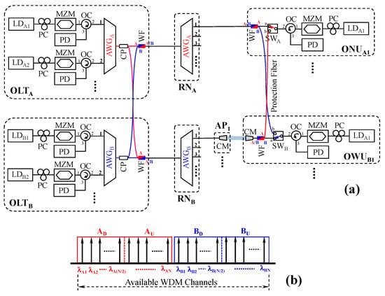
Figure 1.
(a) Proposed hybrid self-restored FSO- and WDM-PON system with fault protection. (b) The periodic characteristic of AWG for the wavelength arrangement of fiber and FSO downstream (AD and BD bands) and upstream signals (AU and BU bands), respectively.
Then, all the downstream traffics will pass through the corresponding feeder fiber, remote node (RNA and RNB) and distribution fiber and enter the optical network unit (ONUA) and optical wireless unit (OWUB), respectively, as exhibited in Figure 1a. The same characteristics of 1 × N AWGA and AWGB are placed in the OLT and RN sides. In the designed network, the difference is that the access points (APs) are placed in the appropriate positions in the FSO access to transmit and receive the bidirectional WDM FSO signals by using the fiber-based collimator (CM) [14,23]. The WF can separate the baseband (A band) and FSO channels (B band) for the corresponding signal transmission. To construct the ONUA, the corresponding upstream LD, WF, PC, OC, MZM, 40 GHz PIN photodiode (PD) and 1 × 2 optical switch (SWA) are used. Moreover, the OWUB uses the same optical components as the ONUA, but only adds the CM for the wireless FSO link, as seen in Figure 1a. Usually, all the SWs of ONUA and OWUB are linked to the “a” point for downstream and upstream path transmission in normal status. Furthermore, the ONUA1 and OWUB1, ONUA2 and OWUB2 and ONUAN and OWUBN are linked by protection fiber and regarded as a group, respectively, for self-restored operation against fiber breakage.
As illustrated in Figure 1a, all the fiber downstream signals of OLTA will pass through the AWGA and AWGB of RNA and RNB via the 1 × 2 CP and then into the corresponding ONUA and OWUB simultaneously. However, all the downstream wavelengths of λA1 to λA(N/2) will be blocked in the related OWUB by the WF. So, the fiber wavelength will not interfere with the FSO signal. Similarly, the entire FSO signals of the OLTB will not enter the corresponding ONUA according to the proposed PON architecture. Therefore, the signal transmissions from the OLTA and OLTB do not interfere with each other.
Generally, we know that fiber breakpoints may occur on the feeder (between OLT and RN) and distribution fibers (between RN and ONU) in PON access [27]. The fiber breakpoints may be caused by nature or man-made factors in the PON network. Once a fiber breakage occurs between the OLT and the RN or RN and ONU/OWU, the corresponding signal link will be disconnected. To avoid the fault happening, a PON network with a self-healing mechanism would be required. Thus, the blended WDM fiber-FSO access architecture with fiber breakage prevention is achieved, as exhibited in Figure 1a. First, we assume that a fiber breakage occurs at the “A1” and “A2” point, respectively, as shown in Figure 2. The “A1” point will cause the entire baseband WDM-PON network to be interrupted. Therefore, each ONUA will not be able to connect to the OLTA. At this time, all the SWA of ONUA switches the connected port to “b” automatically for signal reconnection through the protection fiber and FSO PON architecture, as displayed in Figure 2, while the PD of ONUA cannot detect the corresponding optical downstream signal. In previous studies [28,29], an optical power monitor apparatus had to be included in OLT or ONU to decide whether to switch SW. However, in this design, we do not need to include an additional monitoring device to change the connected position for rerouting the fiber path, only depending on whether the PD detects the downstream signal. In the second case, when the “A2” breakpoint occurs, there will only be a disconnection between the ONUA1 and OLTA. Similarly, the SWA of ONUA1 will connect to “b” for signal retransmission. As a result, no matter whether the fiber fault is at “A1” or “A2” points, it only needs to rely on the SWA of ONUA to switch the connecting fiber path.
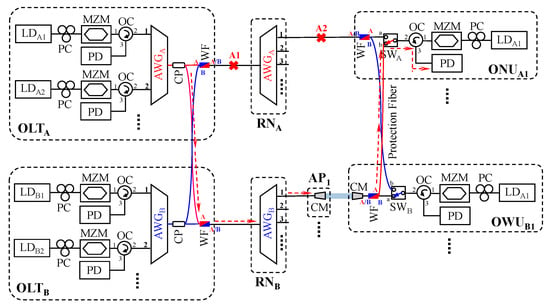
Figure 2.
Assume the fiber breakage occurs at the “A1” and “A2” point in the proposed fiber-FSO WDM-PON system, respectively.
Next, suppose there is a breakpoint location at “B1” or “B2”, which will result in disconnection of FSO traffic between the OLT and entire APs or the RNB and AP1, respectively, as illustrated in Figure 3. Although the B-band FSO signal of OLTB will also be transmitted to the corresponding ONUA via the CP and WF, it will still be separated by the WF of the ONUA. Such FSO signal transmission is similar to that described in Figure 2. Here, to solve the fiber fault occurrence of the presented FSO-PON architecture, the operated mechanism of fault protection is the same as the baseband WDM-PON described above. Likewise, when the “B1” fault occurs, the entire FSO-PON will be unable to connect. The SWB of each OUWB will switch to the “b” position to route the fiber path through the baseband WDM-PON architecture for B-band FSO relink, as shown in Figure 3. Besides, the “B2” breakage only leads to FSO interruption between the RNB and OWUB1.
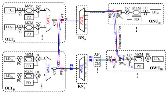
Figure 3.
Assume the fiber breakage occurs at the “B1” and “B2” point in the proposed fiber-FSO WDM-PON system, respectively.
3. Experiment
First, we will confirm the bit error rate (BER) performance of fiber and FSO WDM signals. In the measurement, 24.3 Gbit/s on-off keying (OOK) modulation with a pattern length of 215 − 1 is applied on 40 GHz MZM to produce the symmetric downstream and upstream signals in the presented fiber-FSO PON system. Here, a tunable laser (TL) is applied to represent each LD for the experiment in a convenient manner. The TL has 13 dBm output power and >35 dB optical signal-to-noise ratio (OSNR). The PC is adjusted to tune the properly polarization status in order to achieve the optimal output power.
Four wavelengths of 1528.77 (λA1), 1529.55 (λA2), 1530.33 (λA3) and 1531.12 nm (λA4) are used to act as the downstream (λA1 and λA2) and upstream baseband traffics (λA3 and λA4) in A-band range, respectively. Identically, the other four wavelengths of 1531.90 (λB1), 1532.68 (λB2), 1533.47 (λB3) and 1534.25 nm (λB4) are served as the downstream (λB1 and λB2) and upstream FSO signals (λB3 and λB4) in the B-band window, respectively. Here, the channel spacing of downstream and upstream traffics is 0.8 nm (100 GHz) in the measurement. Due to the wide channel spacing, the inter-channel crosstalk can be ignored. Owing to the 24 and 25 km single-mode fiber (SMF) link, the 24.3 Gbit/s OOK modulation signal is enough to resist fiber dispersion for data transmission. The amplified spontaneous emission (ASE) noise can also filter the AWG. The whole output powers of downstream wavelengths are set at 7.5 dBm after leaving the OLTA and OLTB, as seen in Figure 1. The type optical carrier power of 7.5 dBm is exploited to avoid the non-linear effect in the experiment. As illustrated in Figure 1a, the 16.8 dB total downstream insertion loss of baseband WDM-PON is induced by an AWGA(B) (6 dB), a CP (3 dB), a WF (1.5 dB), a SWA(B) (1 dB), an OC (0.5 dB) and 24 km fiber length (24 × 0.2 = 4.8 dB), respectively. To access the FSO signal, the CM, which has a diameter of 20 mm, divergence angle of 0.016° and focal length of 37.13 mm, respectively, is applied in the execution. Basically, the link loss between two CM is 2.8 dB, when the optimal alignment is achieved. So, the total insertion loss of the FSO system will be 19.6 dB, including the additional FSO link loss. In this setup, in addition to transmitting wireless FSO signals, the CM can also be used to collect the FSO signal. The relevant experimental parameters are listed in Table 1.

Table 1.
Corresponding parameters of experimental setup.
4. Result and Discussion
Figure 4a,b indicate the measured 24.3 Gbit/s BER behaviors of λA1D to λA4U and λB1D to λB4U at the back to back (BtB) condition, respectively. To stay below the forward error correction (FEC) limit (BER of 3.8 × 10⁻³), the detected power sensitivities of λA1D to λA4U and λB1D to λB4U are −33.5, −33.5, −33.5 and −34.0 dBm, and −34.0, −33.5, −33.5 and −32.5 dBm, respectively, as displayed in Figure 4a,b. The received powers of the fiber and FSO signals are between −24.0 and −24.5 dBm under the BER of 10−8 to 10−9. The measured eye diagrams of λA1D to λA4U and λB1D to λB4U are drawn in the insets of Figure 4 at the received powers of −24.0 to −24.5 dBm, respectively. These eyes are clear and open.
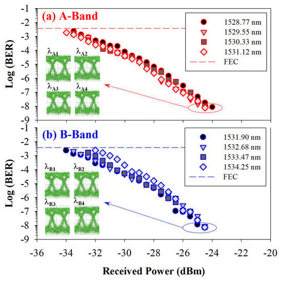
Figure 4.
Measured 24.3 Gbit/s BER behaviors of (a) λA1D to λA4U and (b) λB1D to λB4U at the BtB status, respectively. Insets are the measured eye diagrams of eight wavelengths at the received powers of −24.0 to −24.5 dBm, respectively.
The total length of feeder and distribution fibers is 24 km long, and the protection fiber is 1 km in the next experiment. When the “A1” breakpoint occurs in Figure 2, all the SWA in the ONUA will switch to “b” point to retransmit the bidirectional access signal via the protection fiber path. Then, the 24.3 Gbit/s OOK baseband signals of λA1D to λA4U will reroute through the FSO path connection for bidirectional transmission, as seen in Figure 2. The wireless FSO length is set to 2 m here for convenient measurement. Thus, Figure 5a show the 24.3 Gbit/s BER performances of λA1D to λA4U after passing through a 25 km fiber link and 2 m free space link without using dispersion compensation. Figure 5b presents the BER measurements of λB1D to λB4U FSO signals in the original FSO path (without fiber fault) after 24 km fiber and 2 m wireless FSO connections. All the insets of Figure 5 are the corresponding eye diagrams of λA1D to λA4U and λB1D to λB4U under the BER of 10−8 to 10−9. The eyes are also clear. The corresponding power sensitivities of the eight wavelengths are −27.0, −27.5, −29.0, −29.0, −27.0, −26.5, −27.0 and −26.0 dBm within the FEC target, respectively, as shown in Figure 5a,b. In general, the 24 and 25 km SMF transmission makes no difference to BER performance through 2 m wireless FSO link. This is because the received sensitivity decreases due to the dispersion effect as the modulation signal gradually moves to longer wavelengths. Due to the 1 km protection fiber, the WDM baseband signals will increase 0.2 dB insertion loss. The obtained power budgets of Figure 5a,b will be 34.5, 35, 36.5, 36.5, 34.5, 34, 34.5 and 33.5 dB, respectively, at the wavelengths of 1528.77, 1529.55, 1530.33, 1531.12, 1531.90, 1532.68, 1533.47 and 1534.25 nm. So, the redundant powers of the eight wavelengths are 14.7, 15.2, 16.7, 16.7, 14.9, 14.4, 14.9 and 13.9 dB, respectively. In the wireless FSO connection, the atmospheric scattering, turbulence, absorption and sky background will cause the power loss of free space. Additionally, the misalignment between two CMs also produces power loss. The abovementioned issues will result in poor OSNR and BER performances. Hence, we assume that the FSO transmission is performed in a clean atmosphere. According to the earlier study of an optical FSO system [27], the FSO link length can achieve 860 (13.9 dB) to 1000 m (16.7 dB) based on the corresponding redundant power without optical amplification in the proposed PON network, while the atmospheric condition is in pure status.
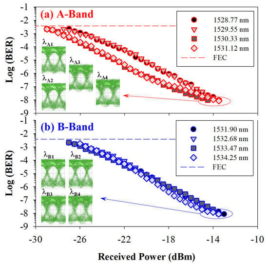
Figure 5.
(a) Measured 24.3 Gbit/s BER performances of λA1D to λA4U via FSO fiber path through 25 km fiber link and 2 m free space link. (b) Obtained BER measurements of λB1D to λB4U in the original FSO fiber path after 24 km fiber and 2 m wireless FSO connections. Insets are the corresponding eye diagrams of eight selected wavelengths.
In the next case, once the “B1” fault is happening in Figure 3, all the FSO signals of λB1D to λB4U will be interrupted. To restore the FSO traffic connection at this time, the SWB can switch to “b” point to route the protection fiber path through fiber WDM-PON architecture. All the downstream and upstream FSO wavelengths will transmit through 25 km fiber link for data reconnection, as seen in Figure 3. Hence, Figure 6a exhibits the obtained 24.3 Gbit/s OOK BER measurements of λA1 to λA4 signals in original fiber link after 24 km transmission. Figure 6b presents the received FSO BER performances of λB1D to λB4U through a 25 km fiber link via the protection fiber. The achieved power sensitivities of λA1 to λA4 and λB1 to λB4 are −27.0, −27.0, −27.5, −27.0, −27.0, −27.5, −26.5 and −26.0 dBm under the FEC target, respectively. The insets of Figure 6 are the obtained corresponding eye diagrams of λA1 to λA4 and λB1 to λB4 under the BER of 10−8 to 10−9, respectively. The observed eyes are also pure. In addition, the achievable power budgets of the eight wavelengths are 34.5, 34.5, 35, 34.5, 34.5, 35, 34 and 33.5 dB, respectively, at the wavelengths of 1528.77, 1529.55, 1530.33, 1531.12, 1531.90, 1532.68, 1533.47 and 1534.25 nm. Additionally, the redundant powers of the eight wavelengths are 17.7, 17.7, 18.2, 17.7, 17.5, 18.0, 17.0 and 16.5 dB, respectively. The redundant powers are sufficient to meet with the total insertion loss induced by presented fiber-FSO WDM-PON architecture for signal connection. The measured results that the obtained power penalty differences between Figure 4 and Figure 5, and Figure 4 and Figure 5 are in the ranges of 4.5 to 7 dB and 6 to 7 dB, respectively, under the FEC threshold.
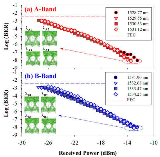
Figure 6.
(a) Measured 24.3 Gbit/s BER performances of λA1D to λA4U in original WDM fiber path through 24 km link. (b) Obtained BER measurements of λB1D to λB4U via the same fiber path after 25 km fiber connection. Insets are the corresponding eye diagrams of eight selected wavelengths.
The difference in BER measured in Figure 5 and Figure 6 is when the fiber breakage occurs on the fiber connection of the WDM fiber and FSO-PON (as seen in Figure 2 and Figure 3), respectively. So, the four WDM fiber (λA1D to λA4U) and four FSO signals (λB1D to λB4U) will reroute the transmission path through the FSO and fiber link as the fault is occurring. Here, there is little difference between the BER measurements obtained in Figure 5 and Figure 6. According to the previous study, the BER performance depends on the total fiber link length. As the total transmission distance of SMF gradually extends, its BER will also deteriorate. Therefore, as long as the total length of the SMF in the PON system remains the same, the BER performance will be no different.
5. Conclusions
We demonstrated a symmetric 24.3 Gbit/s OOK fiber-FSO WDM-PON system to deliver the baseband and FSO signal access. The proposed WDM-PON network also provided a self-restored mechanism to prevent fiber fault occurrence in the feeder and distribution fibers. To avoid WDM signal interference due to RB beat noise, we could separate the available wavelength bandwidth into A and B bands for fiber and FSO signal connections, respectively. Here, the CP and WF were used in the OLTA(B) and the WF and SWA(B) were applied in the ONUA and OWUB to produce the self-protected operation against the fiber breakpoint. Only an active SWA(B) device was employed in the ONUA and OWUB for fault protection. The corresponding ONUAN and OWUBN (N = 1, 2, 3, …) were applied to serve as a group and connected to each other with protection fiber to route the fiber and FSO signal transmission, when the fiber breakage was occurred. In the experiment, 24 km fiber transmission, 1 km protection fiber link and 2 m free space link length were utilized in the proposed PON system to measure BER performances. The fiber and FSO signals of λA1 to λA4 and λB1 to λB4 were applied in the experiment. Here, the power sensitivities of λA1 to λA4 and λB1 to λB4 were obtained between −27.5 and −27.0 dBm and −27.0 and −26.5 dBm in normal states, respectively. When the fault occurred on the baseband and FSO link path, respectively, the obtained power sensitivities of λA1 to λA4 and λB1 to λB4 were from −27.0 to −29.0 dBm and −27.5 to −26.0 dBm, respectively. According to the presented self-restored fiber-FSO WDM-PON architecture, the achieved redundant powers of the eight selected wavelengths could reach the free space transmission length of 860 to 1000 m in normal condition or breakage of fiber. As a result, the proposed fiber-FSO WDM-PON not only provided both baseband and FSO signals, but also supported the self-protected mechanism against fiber breakage.
Author Contributions
Methodology, C.-H.H.; validation, S.-Y.J. and S.-E.H.; experiment, C.-H.H., Y.-T.L. and L.-Y.C.; data curation, C.-H.H.; preparation, S.-Y.J.; writing—original draft, C.-H.Y.; review and editing, C.-H.Y. and C.-W.C.; supervision, S.-K.L. All authors have read and agreed to the published version of the manuscript.
Funding
This research was funded by Ministry of Science and Technology, Taiwan, grant number MOST-110-2221-E-035-058-MY2.
Institutional Review Board Statement
Not applicable.
Informed Consent Statement
Not applicable.
Data Availability Statement
Not applicable.
Conflicts of Interest
The authors declare no conflict of interest.
References
- Wang, H.-Y.; Cheng, C.-H.; Su, B.; Lin, G.-R. QAM-GFDM of dual-mode VCSEL mixed 28-GHz MMW carrier for fiber-wireless link. J. Light. Technol. 2021, 39, 6076–6084. [Google Scholar] [CrossRef]
- Weng, Z.-K.; Chi, Y.-C.; Wang, H.-Y.; Tsai, C.-T.; Lin, G.-R. 75-km long reach dispersion managed OFDM-PON at 60 Gbit/s with quasi-color-free LD. J. Light. Technol. 2018, 36, 2394–2408. [Google Scholar] [CrossRef]
- Nesset, D. NG-PON2 technology and standards. J. Light. Technol. 2015, 33, 1136–1143. [Google Scholar] [CrossRef]
- Kourtessis, P.; Lim, W.; Merayo, N.; Yang, Y.-M.; Senior, J.M. Efficient T-CONT-agnostic bandwidth and wavelength allocation for NG-PON2. J. Opt. Commun. Netw. 2019, 11, 383–396. [Google Scholar] [CrossRef]
- Nguyen, Q.T.; Besnard, P.; Bramerie, L.; Shen, A.; Kazmierski, C.; Chanlou, P.; Duan, G.-H.; Simon, J.-C. Bidirectional 2.5-Gb/s WDM-PON using FP-LDs wavelength-locked by a multiple-wavelength seeding source based on a mode-locked laser. IEEE Photon. Technol. Lett. 2010, 22, 733–735. [Google Scholar] [CrossRef]
- Lee, B.-Y.; Tsai, C.-T.; Lin, H.-S.; Kao, S.-C.; Cheng, C.-H.; Chiang, P.Y.; Lee, H.-C.; Lin, G.-R. C-Band silicon waveguide modulation with 50-Gbit/s NRZ-OOK over 10-km SMF and DSF. IEEE J. Quantum Electron. 2021, 53, 8400109. [Google Scholar] [CrossRef]
- Suzuki, N.; Miura, H.; Matsuda, K.; Matsumoto, R.; Motoshima, K. 100 Gb/s to 1 Tb/s based coherent passive optical network Technology. J. Light. Technol. 2018, 36, 1485–1491. [Google Scholar] [CrossRef]
- Yeh, C.-H.; Wang, B.-Y.; Hsu, W.-H.; Liu, L.-H.; Ko, H.-S. A simple WDM-PON architecture together with private interconnected ONUs. IEEE Access 2021, 9, 126319–126323. [Google Scholar] [CrossRef]
- He, H.; Chen, Y.; Xiao, Q.; Zhou, L.; Dong, Z. LDPC-coded probabilistic shaping PAM4 based on many-to-one mapping in WDM-PON. J. Light. Technol. 2020, 38, 3918–3925. [Google Scholar] [CrossRef]
- Mai, V.V.; Pham, A.T. Integrated FSO/PON for broadband access networks: A comprehensive protocol stack design and analysis. In Proceedings of the IEEE Global Communications Conference (GLOBECOM 2015), San Diego, CA, USA, 6–10 December 2015; pp. 1–7. [Google Scholar]
- Yeh, C.-H.; Chen, J.-R.; You, W.-Y.; Lin, W.-P.; Chow, C.-W. Free space optical communication in long-reach unidirectional ring-architecture fiber network. IEEE Access 2020, 8, 159574–159580. [Google Scholar] [CrossRef]
- Hsu, H.-Y.; Lu, W.C.; Minh, H.L.; Ghassemlooy, Z.; Yu, Y.-L.; Liaw, S.-K. 2 × 80 Gbit/s DWDM bidirectional wavelength reuse optical wireless transmission. IEEE Photon. J. 2013, 5, 7901708. [Google Scholar]
- Ying, C.-L.; Li, C.-Y.; Lu, H.-H.; Chang, C.-H.; Chen, J.-H.; Zheng, J.-R. A hybrid WDM lightwave transport system based on fiber-wireless and fiber-VLLC convergences. IEEE Photon. J. 2014, 6, 7200709. [Google Scholar] [CrossRef]
- Li, C.-Y.; Lu, H.-H.; Tsai, W.-S.; Huang, X.-H.; Wang, Y.-C.; Chen, Y.-N.; Wu, Y.-R. A flexible two-way PM-based fiber-FSO convergence system. IEEE Photon. J. 2018, 10, 7901509. [Google Scholar] [CrossRef]
- Zhang, R.; Tang, X.; Hsu, C.-W.; Chen, Y.-W.; Chang, G.-K. Semi-supervised and supervised nonlinear equalizers in fiber-FSO converged system. J. Light. Technol. 2021, 39, 6175–6181. [Google Scholar] [CrossRef]
- Yeh, C.-H.; Lin, W.-P.; Jiang, S.-Y.; Hsieh, S.-E.; Hsu, C.-H.; Chow, C.-W. Integrated fiber-FSO WDM access system with fiber fault protection. Electronics 2022, 11, 2101. [Google Scholar] [CrossRef]
- Hayal, M.R.; Yousif, B.B.; Azim, M.A. Performance enhancement of DWDM-FSO optical fiber communication systems based on hybrid modulation techniques under atmospheric turbulence channel. Photonics 2021, 8, 464. [Google Scholar] [CrossRef]
- Chowdhury, A.; Chien, H.-C.; Huang, M.-F.; Yu, J.; Chang, G.-K. Rayleigh backscattering noise-eliminated 115-km long-reach bidirectional centralized WDM-PON with 10-Gb/s DPSK downstream and remodulated 2.5-Gb/s OCS-SCM upstream signal. IEEE Photon. Technol. Lett. 2008, 20, 2081–2083. [Google Scholar] [CrossRef]
- Chiuchiarelli, A.; Presi, M.; Proietti, R.; Contestabile, G.; Choudhury, P.; Giorgi, L.; Ciaramella, E. Enhancing resilience to Rayleigh crosstalk by means of line coding and electrical filtering. IEEE Photon. Technol. Lett. 2010, 22, 85–87. [Google Scholar] [CrossRef]
- Xu, J.; Li, M.; Chen, L.-K. Rayleigh noise reduction in 10-Gb/s carrier-distributed WDM-PONs using in-band optical filtering. J. Light. Technol. 2011, 29, 3632–3639. [Google Scholar]
- Chiuchiarelli, A.; Proietti, R.; Presi, M.; Choudhury, P.; Contestabile, G.; Ciaramella, E. Symmetric 10 Gb/s WDM-PON based on a cross wavelength-reusing scheme to avoid rayleigh backscattering and maximize band usage. In Proceedings of the 2009 IEEE LEOS Annual Meeting Conference Proceedings, Belek-Antalya, Turkey, 4–8 October 2009. [Google Scholar]
- Mandal, P.; Sarkar, N.; Santra, S.; Dutta, B.; Kuiri, B.; Mallick, K.; Sekhar, A. Hybrid WDM-FSO-PON with integrated SMF/FSO link for transportation of Rayleigh backscattering noise mitigated wired/wireless information in long-reach. Opt. Commun. 2022, 507, 127594. [Google Scholar] [CrossRef]
- Hayle, S.T.; Manie, Y.C.; Shao, G.-M.; Chiu, P.-H.; Yeh, T.-Y.; You, S.-L.; Peng, P.-C. Integration of fiber and FSO network with fault protection for optical access network. Opt. Commun. 2021, 484, 126676. [Google Scholar] [CrossRef]
- Yeh, C.-H.; Hsu, W.-H.; Wang, B.-Y.; You, W.-Y.; Chen, J.-R.; Chow, C.-W.; Liaw, S.-K. Fiber- and FSO-protected connections for long-reach TWDM access architecture with fault protection. IEEE Access 2020, 8, 189982–189988. [Google Scholar] [CrossRef]
- Yeh, C.-H.; Xie, Y.-R.; Luo, C.-M.; Chow, C.-W. Integration of FSO traffic in ring-topology bidirectional fiber access network with fault protection. IEEE Commun. Lett. 2020, 24, 589–592. [Google Scholar] [CrossRef]
- Garg, A.K.; Metya, S.K.; Singh, G.; Janyani, V.; Aly, M.H.; Zainol Abidin, N.H. SMF/FSO integrated dual-rate reliable and energy efficient WDM optical access network for smart and urban communities. Opt. Quantum Electron. 2021, 53, 625. [Google Scholar] [CrossRef] [PubMed]
- Yeh, C.-H.; Guo, B.-S.; Chang, Y.-J.; Chow, C.-W.; Gu, C.-S. Bidirectional free space optical communication (FSO) in WDM access network with 1000-m supportable free space link. Opt. Commun. 2019, 435, 394–398. [Google Scholar] [CrossRef]
- Wu, C.; Gan, C.; Yang, D.; Chen, B. A self-healing WDM-PON architecture with broadcasting services. Optik 2013, 124, 1669–1671. [Google Scholar] [CrossRef]
- Sun, X.; Chan, C.-K.; Chen, L.-K. A survivable WDM PON with alternate-path switching. In Proceedings of the 2006 Optical Fiber Communication Conference and the National Fiber Optic Engineers Conference, Anaheim, CA, USA, 5–10 March 2006. [Google Scholar]
Publisher’s Note: MDPI stays neutral with regard to jurisdictional claims in published maps and institutional affiliations. |
© 2022 by the authors. Licensee MDPI, Basel, Switzerland. This article is an open access article distributed under the terms and conditions of the Creative Commons Attribution (CC BY) license (https://creativecommons.org/licenses/by/4.0/).