Abstract
The effect of the shape of the nanoparticles and the polarization of incident light on the surface current density and the efficiency of an organic solar cell based on the Tamm plasmon polariton is investigated. In the cases of both elongated and flattened nanoparticles, it is shown that the efficiency of such a solar cell is increased when the electric field vector is parallel to the largest axis of the spheroid.
1. Introduction
Surface waves in photonic structures have attracted the attention of researchers. The surface wave at the boundary between a photonic crystal (PhC) and a medium with negative permittivity [1] is of particular interest. In this case, the surface wave is inseparable from the surface plasmon—the oscillation of free electrons near the surface of a conductor. This coupled mode of the incident field and surface plasmon excitation is called the surface plasmon polariton. In addition to propagating surface waves at the boundary of the PhC and a medium with , it is possible to obtain a state in the form of a standing surface wave, which has a zero wavenumber along the surface and does not transfer energy. Such a state can be excited at the normal incidence of light to the structure. Maxwell’s equation for the electric field, in this case, is an exact analogue of the one-electron Schrodinger equation for a semi-infinite crystal, and its solution is the Tamm surface state. Therefore, the electromagnetic analogue of the Tamm electronic state is called the Tamm plasmon polariton (TPP) [2,3]. The Tamm plasmon polariton is the basis of a fundamentally new class of devices, such as: photoelectrochemical cells [4], absorbers [5,6], sensors [7], lasers [8], beem steering [9], photodetectors [10], and solar cells [11]. The role of the TPP in solar cells is to enhance the absorption in the photosensitive layer. In [12], it was shown that the replacement of an aluminum film with a PhC led to TPP excitation and, as a consequence, an increase in integral absorption by 35 percent. It should be noted that the disadvantage of such a scheme is that part of the incident radiation was absorbed in the silver film. In this regard, in [13], the authors proposed a model of an organic solar cell [14,15,16] in which the photosensitive layer performed two roles simultaneously: as an absorber and a mirror for the TPP excitation. The attractiveness of such a device lies in the fact that it is possible to completely abandon the use of metal contacts, minimizing losses in the structure. The dependence of the integral absorption and efficiency of a TPP-based organic solar cell on the volume fraction of nanoparticles in the photosensitive layer (PSL) was demonstrated in [17]. However, the influence of the shape of the nanoparticles on the integral absorption in the photosensitive layer and the efficiency of the solar cell was not studied. In this regard, this work is devoted to the study of the dependence of the efficiency of a solar cell on the shape of the nanoparticles and the polarization of the incident light.
2. Description of the Model
A sketch of the structure is shown in Figure 1. The photosensitive layer P3HT: PC61BM [18] with a thickness of nm was doped with silver spheroidal nanoparticles (NPs) with a volume fraction of % [18]. The ITO films with thicknesses of 15 nm and 30 nm were used as contacts. The unit cell of the PhC was formed by silicon dioxide (SiO) [19] and titanium dioxide (TiO) [20] with thicknesses of 61 nm and 40 nm, respectively. The reflectance spectrum of the bare PhC is shown in the inset of Figure 1. The PhC band gap was in the range from 350 nm to 520 nm, which means that in this wavelength range, the radiation transmitted through the PSL was reflected from the PhC to pass through the PSL again. The position of the PhC band gap was determined by the fact that the imaginary part of the refractive index of the P3HT:PC61BM had a maximum value in the wavelength range from 350 nm to 600 nm; therefore, the radiation falling onto the structure was absorbed exactly in this spectral band. In the long-wavelength spectral range, the absorption was almost zero. Additional antireflection coating may increase the integral absorption over the entire wavelength range. For simplicity, we did not take this into account. Nonetheless, we ensured the maximal absorption of light reaching the photosensitive layer. The TPP excitation process is explained in detail in Section 3.
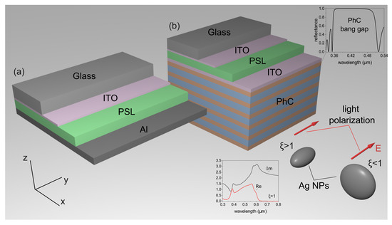
Figure 1.
A sketch of the (a) conventional and (b) TPP-based solar cell. The red arrow shows the direction of the electric field of the incident wave (TM-wave). The direction of the vector perpendicular to the optical axis of the nanoparticles (along the x axis) corresponds to a TE-wave. The reflectance spectra of the bare PhC and real and imagenary parts of the PSL refractive index are shown in the insets.
The permittivity of the PSL with uniformly distributed nanoparticles of the same shape and size was determined by the effective medium theory [21]:
where f is the filling factor, i.e., the fraction of nanoparticles in the matrix; and are the permittivities of matrix and nanoparticles, respectively; and is the radiation frequency. The effective medium theory can be used for simulation of the optical properties of dispersed media with an accuracy comparable to that of the direct calculation [17]. The depolarization factors in Equation (1) depend on the aspect ratio between the lengths of the polar and equatorial semiaxes of the spheroid and on the incident field direction. For the field directed along the y axis, the was determined as
For the field directed along the x axis, the factor was defined as:
where is the aspect ratio. The case corresponded to the flattened spheroid, and the case corresponded to the elongated spheroid. When , we have and .
The permittivity of Ag NPs was defined by the Drude approximation
where is the constant that takes into account the contribution of the interband transitions of the bound electrons, is the plasma frequency, and is the electron relaxation time. We did not separate the absorption in the Ag NPs and in the P3HT:PC61BM material. This was due to the fact that by homogenizing the active layer doped with plasmonic nanoparticles, we obtained a medium with effective parameters. In the wavelength range from 350 nm to 500 nm, we assumed the nanoparticle absorption was smaller than the P3HT:PC61BM absorption (see the inset of Figure 1). Moreover, the nanoparticle absorption was also useful, because it led to the injection of hot electrons and, consequently, to an increase in the photocurrent [22,23].
The transfer matrix method [24] can be used for the simulation of the optical properties of the investigated structure. The variation in the light field upon transmission through each structure layer was determined by a second-order transfer matrix. The transfer matrix of the entire structure that related the amplitudes of the incident and transmitted waves was a product of 2 × 2 matrices
where the transfer matrix was
Here, for the TE-waves (the electric field being perpendicular to the plane of incidence) is the permittivity of the nth layer,
, c is the speed of light, =z–z are the layer thicknesses (n=1,2,…,N), z is the coordinate of the interface between the nth layer and the (n + 1)th layer adjacent from the right, and = 0, is the angle of incident light. The indices 0 and S in Equation (5) denote the media before and behind the photonic crystal. The transfer matrix for the orthogonally polarized TM-wave was obtained from (6) replacing h by the new expression . The energy transmittances, reflectances, and absorbances were determined to be
where are the elements of matrix .
3. Results and Discussion
Figure 2 shows the absorption spectra of the PSL at various values of for conventional and TPP-based organic solar cells. It can be seen from the figure that the replacement of a metal film with a PhC led to an increase in the absorption in the PSL. The greatest increase in absorption was observed inside the band gap of the PhC.
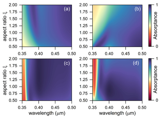
Figure 2.
Absorptance in the PSL with spheroidal NPs in a conventional solar cell shown in Figure 1a for the electric field vector (a) perpendicular and (b) parallel to the optical axis of the NPs in the PSL. Absorptance in the PSL with spheroidal NPs in the TPP-based solar cell shown in Figure 1b for the electric field vector (c) perpendicular and (d) parallel to the optical axis of the NPs in the PSL.
Figure 3a shows the comparative absorptance spectra of the PSL combined with aluminum film and PhC in the case of oblated NPs .
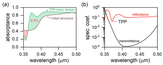
Figure 3.
(a) Absorptance spectra of the PSL–Al (initial structure with aluminum film) and the PSL–PhC (TPP-based design); (b) reflectance and transmittance spectra of the PSL–PhC structure.
It can be seen from the figure that the integral absorption increased by 9.5%. It should be noted that the integral absorption is meant as the PSL absorption normalized to the solar radiation spectrum. Generally, the integral absorption is determined for each of two polarizations, and , separately, and their arithmetic mean yields the total absorption in the layer. In the case of the anisotropic PSL, we have:
where nm, nm, is the absorption in the PSL for the and waves, respectively, and is the solar radiation spectrum (AM1.5).
Such a significant increase in the integral absorption was due to the excitation of the Tamm plasmon polariton at the PhC–PSL interface. To clarify why the TPP excitation led to an increase in the integral absorption, it is necessary to refer to Figure 3b. A minimum of reflection near 370 nm was observed. This minimum corresponded to the critical coupling of the incident field with the TPP. This means that all the radiation incident on the structure was absorbed in the PSL at low values of the transmission coefficient () within the band gap of the PhC. It should be clarified that in this case, the conservation law was not violated, since Figure 3b shows the reflectance and transmittance of the PSL+PhC structure, while Figure 3a shows the absorptance of the PSL without the absorptance of the ITO films. It is important that in comparison with a conventional metal–PhC structure, in our case, a broadband TPP was excited. In this case, the width of the line at its half-height was commensurate with the width of the PhC band gap. This process can be described in more detail using the temporal coupled mode theory, which was described in detail for a similar structure in our previous works [17,25].
The dependences of the integral absorption for the two types of solar cells under consideration at different values of and the direction of the electric field vector relative to the optical axis of nanoparticles in the PSL are shown in Figure 4.
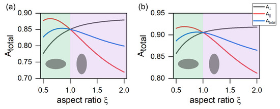
Figure 4.
Integral absorption of the PSL in a structure with an aluminum film (a) and a photonic crystal (b).
It is important to note that the TPP excitation led to an increase in the total integral absorption in the entire range of values of the ratios of the semiaxes of the spheroid, in comparison with the conventional organic solar cell. It is noteworthy that for mutually orthogonal polarizations, the behavior of the integral absorption with an increase in was different. So, in the case when the electric field vector was parallel to the y axis, the integral absorption decreased with an increase in , and for the orthogonal polarization, in contrast, it increased. This behavior of integral absorption can be explained based on the previously mentioned concept of the critical coupling of the Tamm plasmon polariton with the incident field and the temporal coupled mode theory. The energy from the TPP flowed through three channels. The first channel was associated with the PhC transmission, the second and third were associated with the transmission and absorption of the PSL. Within the band gap of a photonic crystal, we can neglect the leakage of energy into the PhC transmission channel. Thus, all the energy localized at the PSL–PhC interface flowed into the two remaining channels. A critical coupling occurred when the rates of energy leakage into these channels were compared. The rates of energy leakage, in turn, were proportional to the absorption and transmission coefficient of the PSL. Thus, the critical coupling corresponded to areas in which the difference between the absorption and transmission was minimal (see Figure 5).
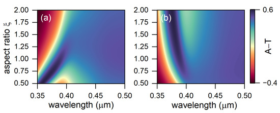
Figure 5.
The difference between the absorption and transmission of the PSL from and the wavelength of the incident light for polarization (a) perpendicular to the optical axis and (b) parallel to the optical axis of the PSL.
It can be seen from the figure that near 370 nm for perpendicular polarization, the difference A-T was minimal for the elongated particles, and for parallel, it was minimal for the flattened ones.
The efficiency of the TPP-based solar cell can be defined by the detailed balance analysis [26,27]. According to this approach, the energy conservation of the solar cell has the form:
where V is the voltage across the cell, J is the total current density, and q is the elementary charge. is the radiative generation of the hole–electron pairs by the incident sunlight, and is the radiative recombination. is the nonradiative recombination of the hole–electron pairs.
The radiative generation can be calculated as:
The radiative recombination relates to the voltage V as:
where is Planck’s law, k is the Boltzman constant, T is the temperature of the cell, h is the Planck constant, and c is the speed of light.
In the case when the contribution of the nonradiative processes is small, the short-circuit current is determined from (9) by equating V to zero:
On the other hand, the open-circuit voltage across the cell can be obtained from (9) by setting :
and the can be approximated as:
In our simulation, only the Auger nonradiative recombination was taken into account:
where (cm/s) is the Auger coefficient [28], and (cm) is the intrinsic carrier concentration.
The efficiency of the solar cell was calculated by the equation [26,27]:
where is the fill factor of the solar cell, and P is the power of incident light. The fill factor is a parameter that, in conjunction with and , determines the maximum power from a solar cell. The FF is defined as the ratio of the maximum power from the solar cell to the product of and , so that:
where and are the current and voltage at the maximal power point of the solar cell, respectively. In our simulation, the and P (W/m).
The calculations showed that for perpendicular polarization, the highest current density (57 A/m) and the efficiency (28.6%), as a consequence, were achieved for the elongated particles at and . For orthogonal polarization, the highest current density (58 A/m) and efficiency (29%) were achieved in the case of the flattened nanoparticles at and (see Figure 6).
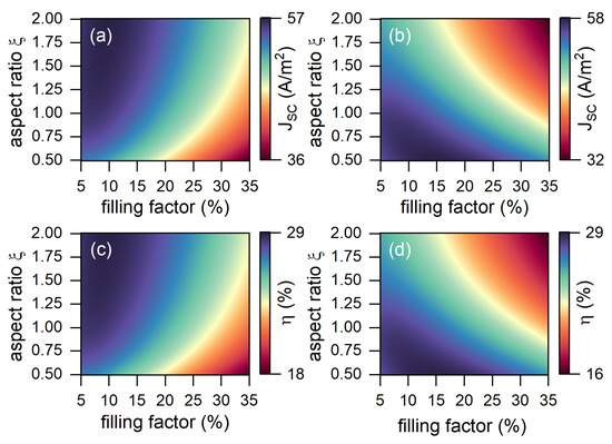
Figure 6.
(a,b) The surface current density and (c,d) the efficiency of the TPP-based solar cell in the case when the electric field vector is perpendicular (a,c) and parallel (b,d) to the y axis.
A comparison of the efficiencies and surface current densities in the cases of the flattened and elongated nanoparticles is presented in Table 1.

Table 1.
Efficiency and current density of the TPP-based solar cell in the case of . The bottom indexes e and f correspond to the elongated and flattened nanoparticles, respectively.
4. Conclusions
The influence of the shape of the nanoparticles and the polarization of incident light on the efficiency of the Tamm-plasmon-polariton-based organic solar cell were investigated. The elongated and flattened nanoparticles were considered in the case when the electric field vector was parallel and perpendicular to the long axis of the nanospheroid. The dielectric permittivity of a photosensitive layer with spheroidal nanoparticles uniformly distributed over the volume was calculated using the effective medium theory. The energy spectra of the structure were calculated by the transfer matrix method. It was found that compared with the conventional organic solar cell, the efficiency of the Tamm-plasmon-polariton-based structure was higher. This was due to the excitation of the Tamm plasmon polariton at the interface between the photonic crystal and photosensitive layer. The highest intensity was achieved for the polarization parallel to the largest axis of the nanospheroid. The results obtained expand the understanding of the effective control of the energy characteristics of the Tamm-plasmon-polariton-based solar cells.
Author Contributions
Conceptualization, R.G.B. and I.V.T.; methodology and software, R.G.B. and I.V.T.; validation, R.G.B., S.Y.V. and V.F.S.; writing—original draft preparation, R.G.B.; visualization, R.G.B.; supervision, I.V.T. and V.F.S. All the authors discussed the results, commented on the manuscript, and agreed to the published version of the manuscript. All authors have read and agreed to the published version of the manuscript.
Funding
The reported study was funded by a grant of the President of the Russian Federation №MK-46.2021.1.2.
Data Availability Statement
The data presented in this study are available upon reasonable request from the corresponding author.
Conflicts of Interest
The authors declare no conflict of interest.
References
- Vinogradov, A.P.; Dorofeenko, A.V.; Merzlikin, A.M.; Lisyansky, A. Surface states in photonic crystals. Physics-Uspekhi 2010, 53, 243–256. [Google Scholar] [CrossRef]
- Kavokin, A.V.; Shelykh, I.A.; Malpuech, G. Lossless interface modes at the boundary between two periodic dielectric structures. Phys. Rev. B 2005, 72, 233102. [Google Scholar] [CrossRef]
- Kaliteevski, M.; Iorsh, I.; Brand, S.; Abram, R.A.; Chamberlain, J.M.; Kavokin, A.V.; Shelykh, I.A. Tamm plasmon-polaritons: Possible electromagnetic states at the interface of a metal and a dielectric Bragg mirror. Phys. Rev. B 2007, 76, 165415. [Google Scholar] [CrossRef]
- Pyatnov, M.; Bikbaev, R.; Timofeev, I.; Ryzhkov, I.; Vetrov, S.; Shabanov, V. Broadband Tamm Plasmons in Chirped Photonic Crystals for Light-Induced Water Splitting. Nanomaterials 2022, 12, 928. [Google Scholar] [CrossRef] [PubMed]
- Wu, F.; Wu, X.; Xiao, S.; Liu, G.; Li, H. Broadband wide-angle multilayer absorber based on a broadband omnidirectional optical Tamm state. Opt. Express 2021, 29, 23976. [Google Scholar] [CrossRef] [PubMed]
- Xue, C.H.; Wu, F.; Jiang, H.T.; Li, Y.; Zhang, Y.W.; Chen, H. Wide-angle Spectrally Selective Perfect Absorber by Utilizing Dispersionless Tamm Plasmon Polaritons. Sci. Rep. 2016, 6, 39418. [Google Scholar] [CrossRef]
- Juneau-Fecteau, A.; Savin, R.; Boucherif, A.; Fréchette, L.G. A practical Tamm plasmon sensor based on porous Si. AIP Adv. 2021, 11, 065305. [Google Scholar] [CrossRef]
- Xu, W.H.; Chou, Y.H.; Yang, Z.Y.; Liu, Y.Y.; Yu, M.W.; Huang, C.H.; Chang, C.T.; Huang, C.Y.; Lu, T.C.; Lin, T.R.; et al. Tamm Plasmon-Polariton Ultraviolet Lasers. Adv. Photonics Res. 2021, 3, 2100120. [Google Scholar] [CrossRef]
- Bikbaev, R.G.; Maksimov, D.N.; Chen, K.P.; Timofeev, I.V. Double-Resolved Beam Steering by Metagrating-Based Tamm Plasmon Polariton. Materials 2022, 15, 6014. [Google Scholar] [CrossRef] [PubMed]
- Wang, J.; Zhu, Y.; Wang, W.; Li, Y.; Gao, R.; Yu, P.; Xu, H.; Wang, Z. Broadband Tamm plasmon-enhanced planar hot-electron photodetector. Nanoscale 2020, 12, 23945–23952. [Google Scholar] [CrossRef]
- Bikbaev, R.G.; Vetrov, S.Y.; Timofeev, I.V.; Shabanov, V.F. Tamm Plasmon Polaritons for Light Trapping in Organic Solar Cells. Dokl. Phys. 2020, 65, 161–163. [Google Scholar] [CrossRef]
- Zhang, X.L.; Song, J.F.; Li, X.B.; Feng, J.; Sun, H.B. Optical Tamm states enhanced broad-band absorption of organic solar cells. Appl. Phys. Lett. 2012, 101, 243901. [Google Scholar] [CrossRef]
- Bikbaev, R.G.; Vetrov, S.Y.; Timofeev, I.V.; Shabanov, V.F. Photosensitivity and reflectivity of the active layer in a Tamm-plasmon-polariton-based organic solar cell. Appl. Opt. 2021, 60, 3338. [Google Scholar] [CrossRef] [PubMed]
- Chen, L.X. Organic Solar Cells: Recent Progress and Challenges. ACS Energy Lett. 2019, 4, 2537–2539. [Google Scholar] [CrossRef]
- Yang, F.; Huang, Y.; Li, Y.; Li, Y. Large-area flexible organic solar cells. Npj Flex. Electron. 2021, 5, 30. [Google Scholar] [CrossRef]
- Li, Y.; Huang, W.; Zhao, D.; Wang, L.; Jiao, Z.; Huang, Q.; Wang, P.; Sun, M.; Yuan, G. Recent Progress in Organic Solar Cells: A Review on Materials from Acceptor to Donor. Molecules 2022, 27, 1800. [Google Scholar] [CrossRef] [PubMed]
- Bikbaev, R.G.; Pykhtin, D.A.; Vetrov, S.Y.; Timofeev, I.V.; Shabanov, V.F. Nanostructured photosensitive layer for Tamm-plasmon-polariton-based organic solar cells. Appl. Opt. 2022, 61, 5049. [Google Scholar] [CrossRef]
- Stelling, C.; Singh, C.R.; Karg, M.; König, T.A.F.; Thelakkat, M.; Retsch, M. Plasmonic nanomeshes: Their ambivalent role as transparent electrodes in organic solar cells. Sci. Rep. 2017, 7, 42530. [Google Scholar] [CrossRef]
- Malitson, I.H. Interspecimen Comparison of the Refractive Index of Fused Silica. J. Opt. Soc. Am. 1965, 55, 1205–1209. [Google Scholar] [CrossRef]
- DeVore, J.R. Refractive Indices of Rutile and Sphalerite. J. Opt. Soc. Am. 1951, 41, 416–419. [Google Scholar] [CrossRef]
- Colours in metal glasses, in metallic films and in metallic solutions—II. Proc. R. Soc. London. Ser. A Contain. Pap. A Math. Phys. Character 1905, 76, 370–373. [CrossRef]
- Chen, L.; Mao, S.; Wang, P.; Yao, Z.; Du, Z.; Zhu, Z.; Belfiore, L.A.; Tang, J. Visible Light Driven Hot-Electron Injection by Pd Nanoparticles: Fast Response in Metal–Semiconductor Photodetection. Adv. Opt. Mater. 2020, 9, 2001505. [Google Scholar] [CrossRef]
- Lee, D.; Han, S.G.; Mun, J.; Yang, K.; Kim, S.H.; Rho, J.; Cho, K.; Oh, D.X.; Jeong, M.S. Elucidating the photoluminescence-enhancement mechanism in a push-pull conjugated polymer induced by hot-electron injection from gold nanoparticles. Photonics Res. 2021, 9, 131. [Google Scholar] [CrossRef]
- Yeh, P. Electromagnetic propagation in birefringent layered media. J. Opt. Soc. Am. 1979, 69, 742. [Google Scholar] [CrossRef]
- Vyunishev, A.M.; Bikbaev, R.G.; Svyakhovskiy, S.E.; Timofeev, I.V.; Pankin, P.S.; Evlashin, S.A.; Vetrov, S.Y.; Myslivets, S.A.; Arkhipkin, V.G. Broadband Tamm plasmon polariton. J. Opt. Soc. Am. B 2019, 36, 2299–2305. [Google Scholar] [CrossRef]
- Kim, K.; Lee, S. Detailed balance analysis of plasmonic metamaterial perovskite solar cells. Opt. Express 2019, 27, A1241. [Google Scholar] [CrossRef] [PubMed]
- Sandhu, S.; Yu, Z.; Fan, S. Detailed balance analysis of nanophotonic solar cells. Opt. Express 2013, 21, 1209. [Google Scholar] [CrossRef] [PubMed]
- Kirchartz, T.; Pieters, B.E.; Kirkpatrick, J.; Rau, U.; Nelson, J. Recombination via tail states in polythiophene:fullerene solar cells. Phys. Rev. B 2011, 83. [Google Scholar] [CrossRef]
Publisher’s Note: MDPI stays neutral with regard to jurisdictional claims in published maps and institutional affiliations. |
© 2022 by the authors. Licensee MDPI, Basel, Switzerland. This article is an open access article distributed under the terms and conditions of the Creative Commons Attribution (CC BY) license (https://creativecommons.org/licenses/by/4.0/).