Communication

Application of a Novel Nd:YAG/PPMgLN Laser Module Speckle-Suppressed by Multi-Mode Fibers in an Exhibition Environment

1
School of Cultural Industries and Tourism, Xiamen University of Technology, Xiamen 361024, China
2
Fujian Zoomking Technology Co., Ltd., Longyan 364100, China
3
Fujian Key Laboratory of Optoelectronic Technology and Devices, Xiamen University of Technology, Xiamen 361024, China
*
Author to whom correspondence should be addressed.
Photonics 2022, 9(1), 46; https://doi.org/10.3390/photonics9010046
Submission received: 27 December 2021 / Revised: 10 January 2022 / Accepted: 14 January 2022 / Published: 16 January 2022
(This article belongs to the Section Lasers, Light Sources and Sensors)

Abstract

:
Laser exhibition technology has been widely used in the virtual environment of exhibitions and shows, as well as in the physical conference and exhibition centers. However, the speckle issue due to the high coherence of laser sources has caused harmful impacts on image quality, which is one of the obstacles to exhibition effects. In this paper, we design a compact Nd:YAG/PPMgLN laser module at 561.5 nm and use two different types of big-core multi-mode fibers to lower the spatial coherence. According to our experiment, the speckle contrasts relating to these two types reduce to 7.9% and 4.1%, respectively. The results of this paper contribute to improving the application effects of key optical components in the exhibitions. Only in this way can we provide technical supports and service guarantee for the development of the exhibition activities, and an immersive interactive experience for the audiences.

1. Introduction

With the rapid development of information and communication technologies (ICTs), audiences’ demands for audio-visual effects have gradually increased. This has led to obvious shifts in product content, key technologies, business models and application scenarios in the exhibition industry [1,2]. According to current studies, the requirements of exhibitions and shows cannot be met adequately by means of traditional photo-electric technologies while modern forms of exhibitions and shows have made some headway by virtue of optical techniques, computer techniques, landscape design and art media [3,4]. Laser exhibition technology combines exhibition scenes with virtual illusions and reality by means of the coordination and adjustment of light, which provides a more attractive, stunning and realistic effect for the audiences on the spot [5]. Laser exhibition technology integrates holographic techniques and gesture control technology, realizing the interaction of humans and exhibits and audience-stereoscopic images [6,7].
Under the influence of laser technologies, breakthroughs in artistic exhibitions have been achieved. However, there still remain key technological issues to be solved, such as laser sources, optical coupling, laser speckles, as well as color restoration and correction [8,9]. In this paper, we design a novel Nd:YAG/PPMgLN laser source module at 561.5 nm and use two different types of big-core multi-mode fibers to suppress the speckle effect, in order to achieve a better exhibition effect for visitors and audiences and promote the development of the conference and exhibition industry.

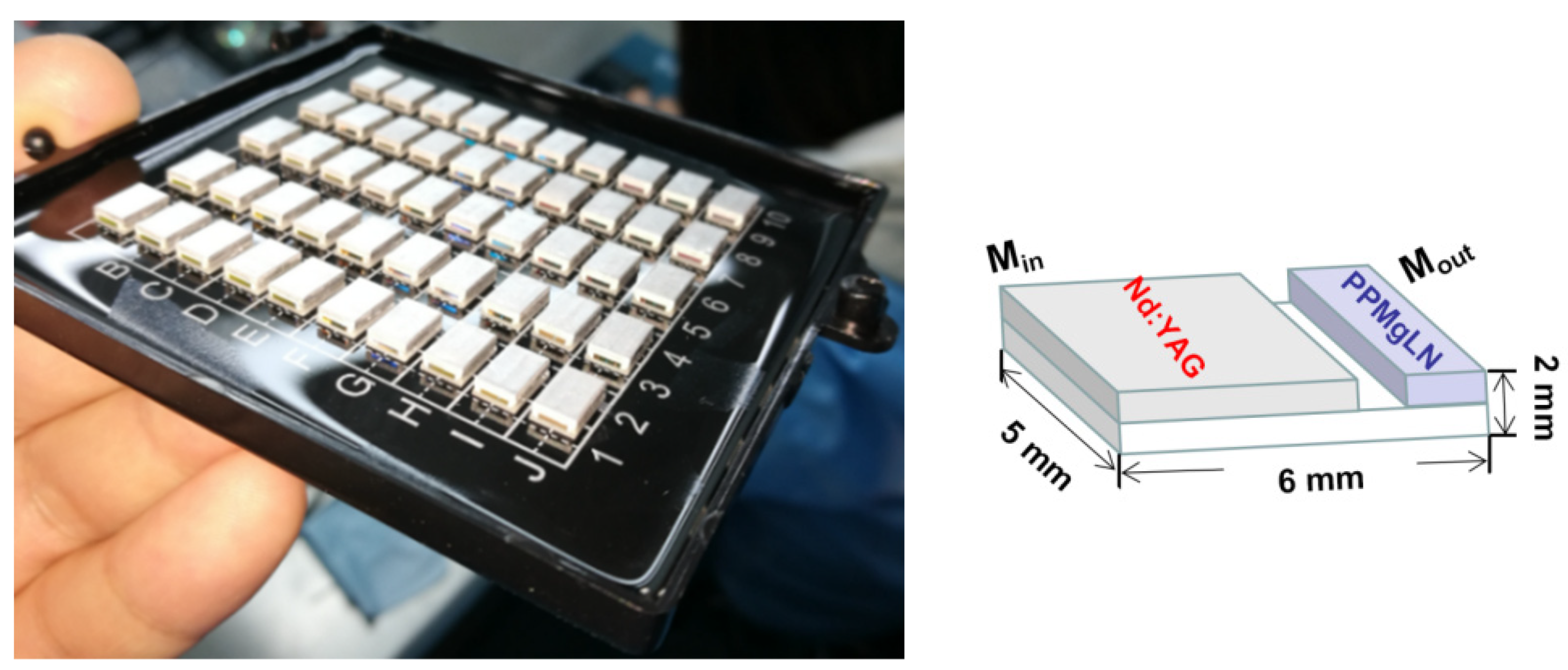
2. Nd:YAG/PPMgLN Module at 561.5 nm

2.1. Properties of the Nd:YAG/PPMgLN Module

The PPMgLN crystal is one of the most effective non-linear media, which can turn a near-infrared fundamental laser into visible light based on the double-frequency method [10,11,12,13]. The physical picture and the schematic drawing of the Nd:YAG/PPMgLN module at 561.5 nm are shown in Figure 1. This module is very simple, compact and efficient [14]. Here, the novel module consists of a PPMgLN crystal, an Nd:YAG gain medium, a silicon wafer, and an aluminum housing. The well-designed coating of this module directly adheres to the facets of the Nd:YAG/PPMgLN crystal. The length of the Nd:YAG crystal is 3 mm. The left facet (Min) of the Nd:YAG crystal has a high-reflection (HR) coating at 1123.0 nm and a high-transmittance (HT) coating at 808.0, 1064.0 and 1319.0 nm. The right facet has an HR coating at 561.5 nm and an HT coating at 946.0, 1064.0, 1123.0 and 1319.0 nm.
The length of the PPMgLN crystal is 2 mm. The left facet of the PPMgLN crystal has an HT coating at 561.5, 946.0, 1064.0, 1123.0 and 1319.0 nm. The right facet (Mout) has an HR coating at 1123.0 nm and an HT coating at 561.5, 946.0, 1064.0 and 1319.0 nm. The module is directly pumped by a 3 W c-mount LD, and the output power at 561.5 nm is 250 mW at the pump power of 2.5 W with the conversion efficiency of 10%.

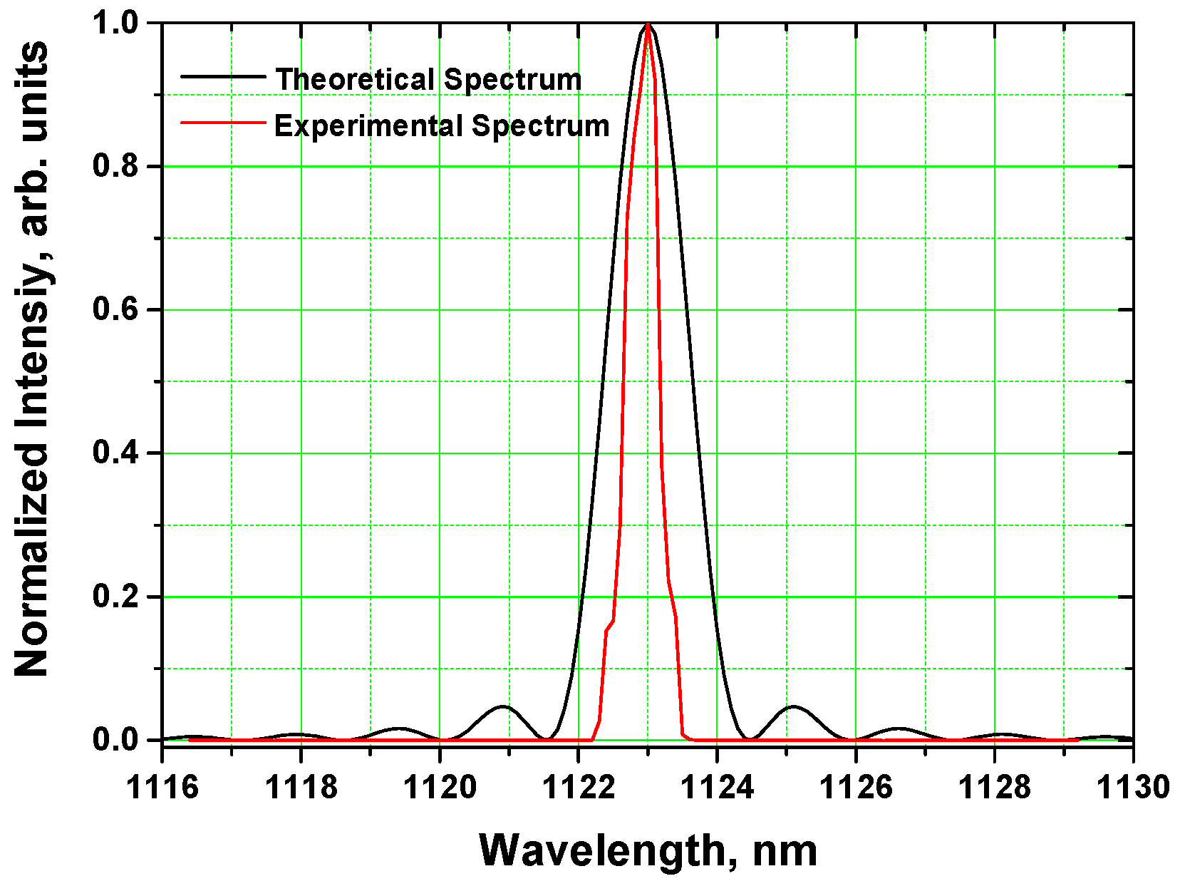
2.2. Spectral Characteristic of the Nd:YAG/PPMgLN Laser
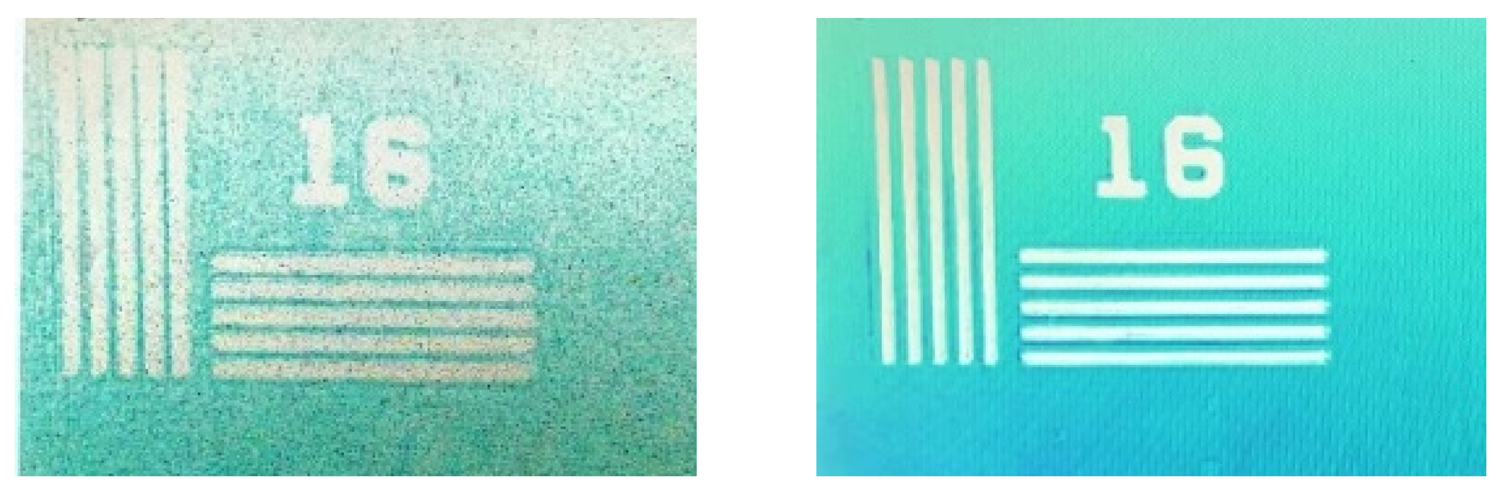
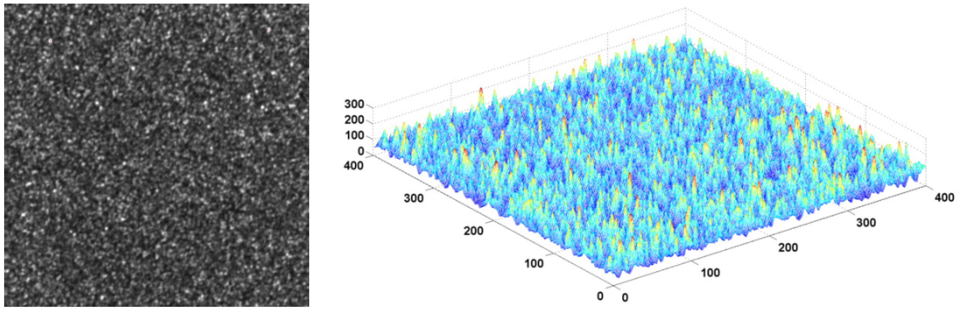
Spectral characteristics are the key parameter for speckle analysis. In theory, for the constant fundamental light and the plane wave, the doubled-frequency efficiency η can be written as:
η sin c 2 ( Δ k L 2 )
L is the length of the PPMgLN crystal. Δk is the phase mismatch factor for quasi-phase-matching, which is written as:
Δ k = 2 π [ n ( λ 2 ω , T ) λ 2 ω n ( λ ω , T ) λ ω 1 Λ ]
λω and λ2ω are the wavelengths of the fundamental light and frequency-doubled light. n, Λ and T are the refractive index, period and temperature of the PPMgLN crystal, respectively. The Sellmeier equation for the PPMgLN crystal [15] is:
n 2 ( λ , T ) = 5.319725 + 4.753496 × 10 7 f + 0.09147285 + 3.310965 × 10 8 f λ 2 0.3165008 2 + 100.2028 + 2.760513 × 10 5 f λ 2 11.37639 2 1.497046 × 10 2 λ 2
f is the temperature parameter, and it can be described as follows:
f = ( T 24.5 ) ( T + 470.82 )
When the PPMgLN length is 2 mm, the direct relationship between the normalized efficiency and the fundamental wavelength is calculated and is shown in Figure 2. The black line represents the theoretical calculation of the normalized efficiency versus the fundamental wavelength. The red line is the actually measured spectrum of the fundamental light. From the viewpoint of theory, the acceptance band-width at 1123.0 nm is 1.2 nm, i.e., 1122.4–1123.6 nm. Therefore, the spectral line-width of the frequency-doubled light at 561.5 nm is 0.6 nm, i.e., 561.2–561.8 nm.
In our experiment, the actual fundamental line-width at 1123.0 nm is only 0.6 nm, i.e., 1122.7–1123.3 nm. Therefore, the corresponding line-width at 561.5 nm is only 0.3 nm, i.e., 561.35–561.65 nm. The coherence time (τc) and coherence length (Lc) at 561.5 nm can be written as:
L c = λ 0 2 Δ λ
τ c = L c c = λ 0 2 Δ λ 1 c
c, λ0 and Δλ are the speed of light, the wavelength and the spectral line-width at 561.5 nm in a vacuum, respectively. The coherence length and coherence time at 561.5 nm are 1.05 mm and 3.5 ps, respectively. Here, the fundamental wavelength is fixed, so it is not easy to widen the line-width at 561.5 nm with only one PPMgLN crystal to decrease the temporal coherence [16].

3. Laser Speckle

When the Nd:YAG/PPMgLN laser beam at 561.5 nm irradiates an imaging plate, uneven intensity distribution can be shown in Figure 3. The bright spots are the interference enhancement of diffuse reflections in each small rough facet of the imaging plate, while the dark spots are the destructive interference of coherent light. We obtain the laser illumination image by a CCD camera and its 3D intensity distribution is analyzed by MATLAB. The standard deviation and the mean value of the illumination image can be calculated, and their ratio reflects the speckle contrast. Speckle contrast is 46.2%. Obviously, the light intensity distribution is very uneven. The relative intensity ratio has changed from 25 to 250, and the difference ratio is 225.
In the field of laser exhibitions, speckle can lead to the partial loss of image information and the reduction of image resolution [17]. In order to improve the visitors’ experience, it is necessary to suppress the laser speckle by means of laser technology. There are three ways to eliminate the laser speckle: (a) by reducing the temporal coherence; (b) by reducing spatial coherence; and (c) by dynamic superposing multiple images [18,19]. In 2016, Z. Xin reported an efficient, wide line-width and speckle-reduced green output by second harmonic generation with a multiple LBO crystal cascade [16]. When three-crystal cascade was used, the acceptance band-width at 1064 nm reaches 8 nm with a high conversion efficiency of 30.5%. The wider line-width of the green laser can further reduce the temporal coherence and eliminate the laser speckle.
The introduction of a multi-mode fiber is also an effective method to weaken laser speckle. It is also beneficial to laser transmission with less energy loss [20,21,22]. By meticulously changing the core diameter and the numerical aperture of the gradient-index fiber, the phase differences between each mode may vary randomly over time. Therefore, the “boiling” speckle pattern also alters over time and superimposes on the receiving screen [23]. Due to vision persistence of human eyes, the intensity superposition of multiple speckle patterns can reduce the speckle contrast effectively. In 2019, Y. Yoon used a diamond/KBr diffuser coupled with a multi-mode fiber to reduce the speckle noise of a tunable external cavity quantum cascade lasers [24]. In this paper, we use two different types of big-core multi-mode fibers to lower the spatial coherence of the Nd:YAG/PPMgLN laser at 561.5 nm.

4. Speckle-Suppressed Technology Based on Multi-Mode Fibers

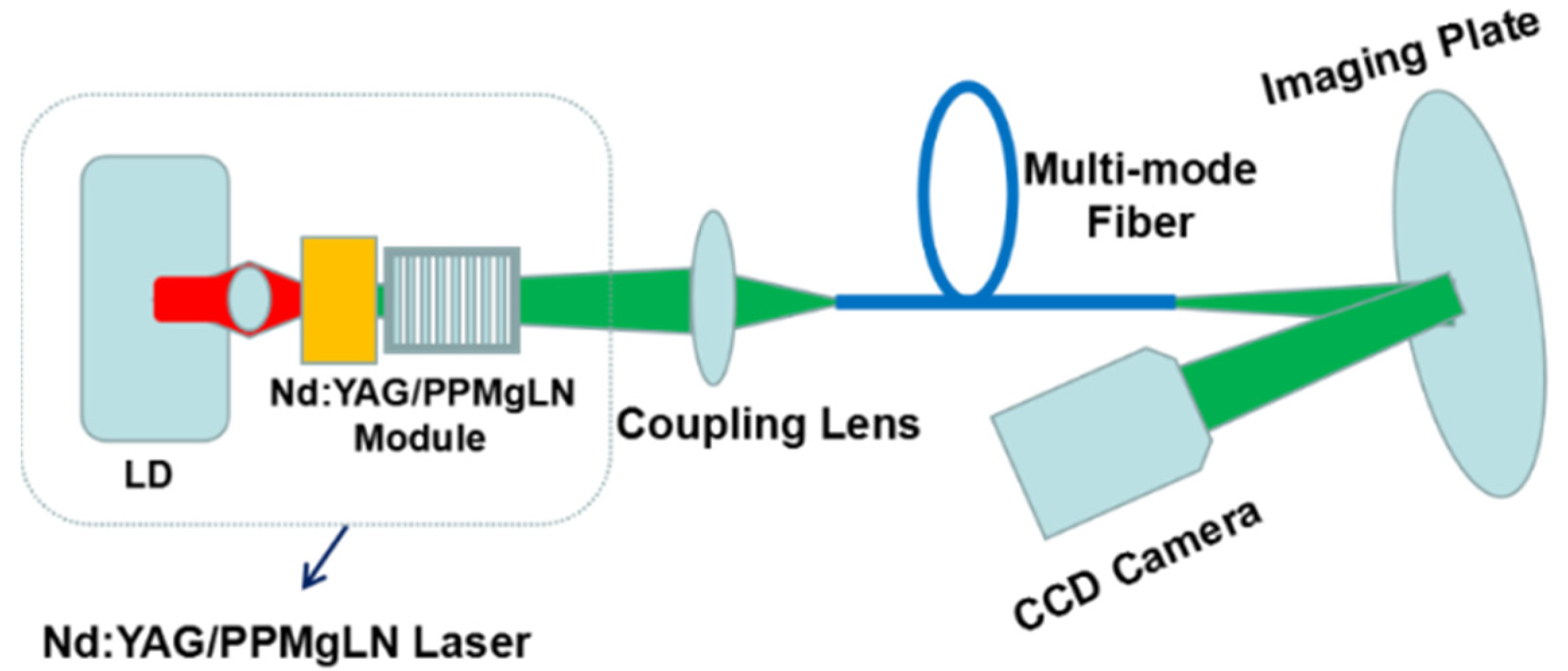
4.1. Experimental Setup of Speckle-Suppressed Technology Based on Multi-Mode Fibers

We employ two types of big-core multi-mode fibers to reduce speckle contrast. The experimental setup includes an Nd:YAG/PPMgLN laser at 561.5 nm, a coupling lens, a multi-mode fiber, an imaging plate and a CCD camera (FT-CS140H, Fortune Techno. Ltd., Shenzhen, China) as shown in Figure 4. The laser at 561.5 nm is coupled in the multi-mode fiber by the coupling lens and then illuminates the white imagining plate. We choose SUH500 multi-mode quartz fibers and a 1000/2200 multi-mode plastic fiber for our experiment. The laser illumination image is detected by the CCD camera, and 3D intensity distribution is analyzed by MATLAB.
We can use the inter-modal dispersion of the multi-mode gradient-index fiber to reduce spatial coherence, with its schematic diagram shown in Figure 5. Moreover, the multi-mode fiber can disturb the polarization characteristics of the propagating light, which contributes to suppressing the laser speckle.

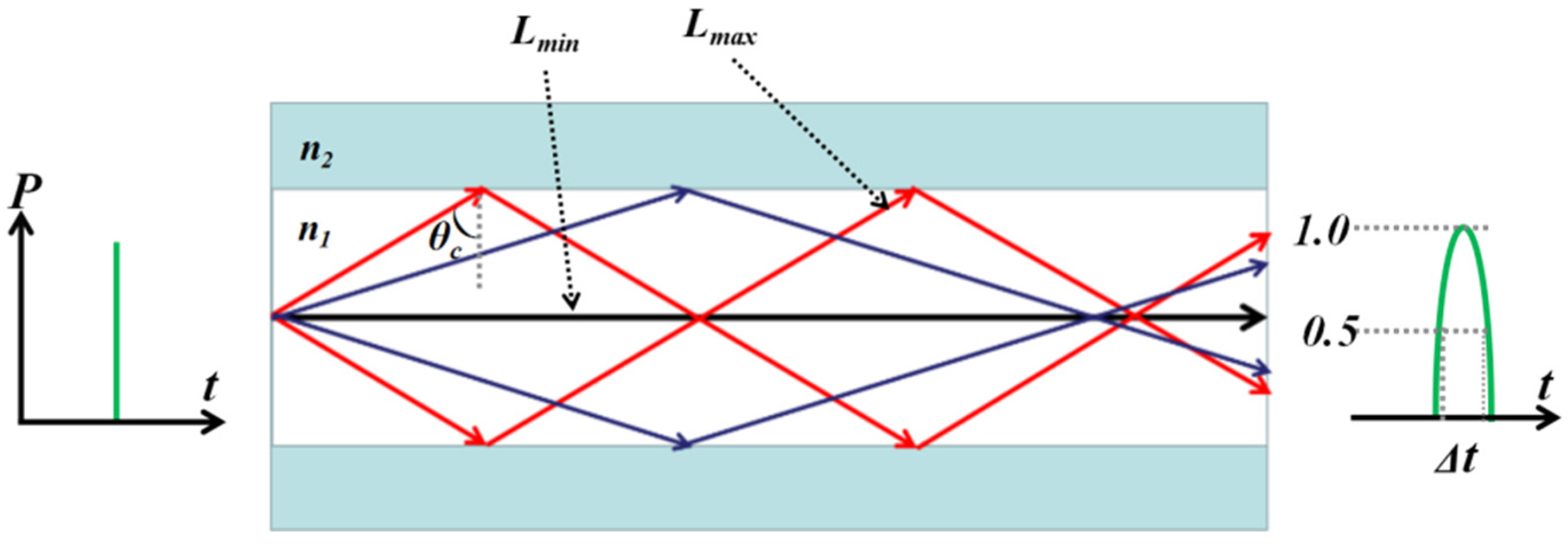
4.2. The Dispersion Characteristics of the Multi-Mode Fibers

According to the selected fiber parameters, such as the core diameter (d), the numerical aperture (NA) and the wavelength of the transmitted light (λ0), the number of propagation modes (N) of the multi-mode fiber is written as:
N π d λ 0 ( N A )
The number of modes (N) is proportional to the core diameter (d) and the numerical aperture (NA). For the multi-mode quartz fiber, the transmitted wavelength and the numerical aperture are 561.5 nm and 0.2, respectively. When the core diameters are 50, 100, 200, 300 and 475 μm, respectively, the numbers of corresponding modes are 56, 112, 224, 336 and 531. For the multi-mode plastic fiber, the numerical aperture is 0.5 and the core diameter is 1000 μm. Then, the final result for the number of modes is 2797. Obviously, the bigger the core diameter and the numerical aperture, the greater the number of fiber modes as well as the greater the dispersion.
Furthermore, the propagation delay time (Δt) of the multi-mode fiber can be written as:
Δ t = n 1 ( L max L min ) c L min 2 c n 1 ( N A ) 2 = L 2 c n 1 ( N A ) 2
L is the length of the multi-mode fiber. Lmax and Lmin are the maximum propagation distance and the minimum propagation distance between the different modes of the multi-mode fiber. Formula (8) shows that delay time (Δt) is proportional to the fiber length (L) and the square of numerical aperture (NA)2. The longer the L is, the larger the NA, as well as the larger the time difference (Δt) between multiple communication modes. For the multi-mode plastic fiber with the numerical aperture of 0.5 and the core refractive index of 1.516, the delay time reaches 275 ps. However, for the multi-mode quartz fiber with the numerical aperture of 0.2 and the core refractive index of 1.450, the delay time is only 46 ps. Every delay time (Δt) of these multi-mode fibers is longer than the coherence time (τc) of the Nd:YAG/PPMgLN laser at 561.5 nm, and these multi-mode fibers can be used to lower the spatial coherence.

5. Results and Discussion

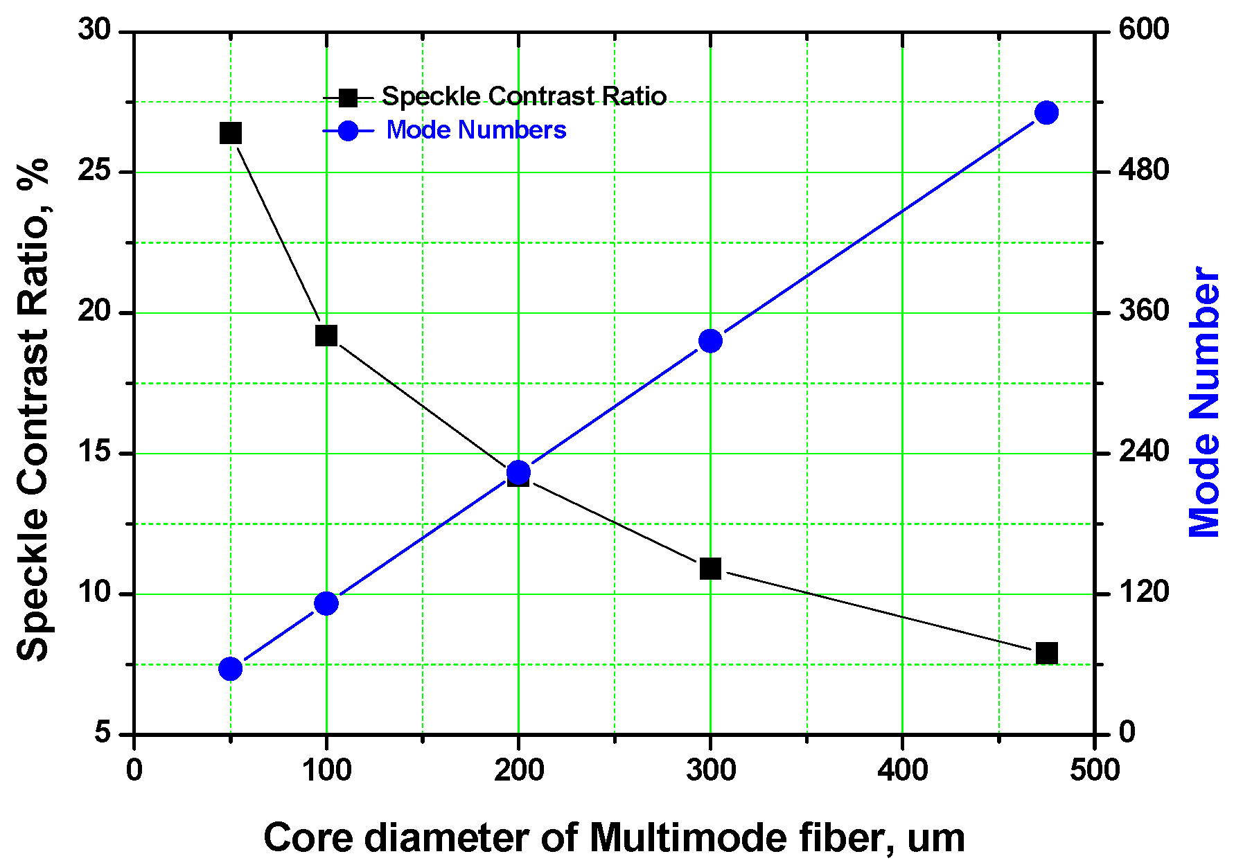
5.1. Multi-Mode Quartz Fibers

The aforementioned SUH500 multi-mode quartz fibers with five different cores are used. Their core diameters are 50, 100, 200, 300 and 475 μm, respectively, with the same length of 1 m. The speckle contrast ratios versus the core diameters of the quartz fibers are shown in Figure 6. The speckle contrast ratios are 26.4%, 19.2%, 14.2%, 10.9% and 7.9%, when the mode numbers of these multi-mode fibers are 56, 112, 224, 336 and 531, respectively. The growth of the core diameter and mode number can greatly decrease the speckle contrast.
In the integration time of the CCD camera, the superpositions of some speckle structures constituted by the corresponding different fiber modes could weaken the speckle contrast to a certain extent. The specific weakening degree is determined by the relationship among the speckle structures of all the fiber modes. When these speckle structures are independent of one another, the speckle contrast could decrease significantly. When these speckle structures are completely coherent, the contrast is the same as that in free space. Among these quartz fibers, the 475/500 SUH500 multi-mode fiber possesses the largest mode number of 531, so it reveals the maximum incoherent superpositions with the lowest speckle contrast ratio of 7.9%.
The laser illumination image and 3D intensity distribution of the 475/500 SUH500 multi-mode fiber are shown in Figure 7. The speckle is very obvious before passing the 475/500 SUH500 fiber, however, the intensity distribution homogenizes with the speckle contrast reduction of 7.9% after passing the multi-mode fiber. The value range of relative strength is 80, i.e., 160–240. The power at 561.5 nm is 233 mW with the total coupling efficiency of 93%.

5.2. Multi-Mode Plastic Fiber

The 1000/2200 multi-mode plastic fiber is also used to further reduce the laser speckle. The intensity distribution becomes better-distributed after passing the plastic fiber, and the speckle contrast reduces to 4.1%. The range of relative strength value is 50, i.e., 180–230 in Figure 8. Moreover, the power at 561.5 nm is 223 mW with the total coupling efficiency of 89%.
The multi-mode plastic fiber has the maximum mode number of 2797 and the longest propagation delay time of 275 ps. Therefore, the speckle-suppressed effect is the most obvious. When the delay time of multiple modes (Δt) is more than the coherence time (τc) of the spectrum, that is to say, optical path difference between adjacent modes exceeds coherence length (Lc), more temporal coherence could be weakened significantly. Furthermore, the longer the L is, the larger the NA, as well as the greater the reduction of the temporal coherence. Therefore, the more independent speckle patterns that are obtained, the more obvious is the speckle contrast reduction.
The 561.5 nm laser is used as the illumination light to make a comparison in the display images of a resolution test target between speckle pre-suppression and speckle post-suppression in Figure 9. It can be seen that the resolution of the image (left) is very poor due to the influence of speckle. However, because of the inter-modal dispersion in the multi-mode gradient-index fiber, the strong coherence of the laser with the multi-mode plastic fiber is destroyed and the image speckle is suppressed. The information points of the disc image (right) can be clearly observed and the imaging quality has been greatly improved. This laser with low-contrast speckle of 4.1% can be applied for laser illumination in the exhibition industry.

6. Conclusions

In summary, a low-power laser at 561.5 nm for exhibit illumination is developed in this paper. The Nd:YAG/PPMgLN module at 561.5 nm is very simple, compact and efficient. The speckle contrast reduces to 4.1% by means of a 1000/2200 multi-mode plastic fiber, and the power at 561.5 nm is 223 mW. The speckle-suppressed Nd:YAG/PPMgLN laser at 561.5 nm can be used for exhibit illumination due to the low speckle contrast of 4.1%. The results and findings of our laser source experiment can be applied in multiple scenarios and situations in the virtual exhibition industry, such as cultural and historical relic shows, art exhibitions, commercial displays and interactive performance, as well as in conference and exhibition centers, museums, archives and libraries. Relying on this speckle-suppressed laser in this research, exhibitions and shows can provide clear and high-quality visual images and achieve a better exhibition effect to fulfill the needs of the audience. The exhibition effects of art works are enhanced with the application of laser exhibition technology, providing a more immersive experience for audiences.

Author Contributions

Conceptualization, X.L. and H.-Y.L.; methodology, X.L., X.-T.Z. and H.-Y.L.; software, S.-F.B. and T.Y.; validation, X.L., T.Y. and H.-Y.L.; formal analysis, X.L., X.-T.Z., W.-J.S. and H.-Y.L.; investigation, X.L. and X.-T.Z.; resources, X.L. and W.-J.S.; data curation, S.-F.B. and H.-Y.L.; writing—original draft preparation, X.L.; writing—review and editing, X.L. and H.-Y.L.; visualization, T.Y. and S.-F.B.; supervision, H.-Y.L.; funding acquisition, X.L. All authors have read and agreed to the published version of the manuscript.

Funding

This research was funded by the National Social Science Fund of China, grant number 16CGL021.

Institutional Review Board Statement

Not applicable.

Informed Consent Statement

Not applicable.

Data Availability Statement

The data presented in this study are available on request from the corresponding author. The data are not publicly available due to privacy.

Acknowledgments

We are very grateful to the relevant fund of its support and reviewers’ valuable comments for this paper.

Conflicts of Interest

The authors declare no conflict of interest.

References

  1. Liu, X.; Seevers, R.; Gu, Z.; Yang, X. Smart MICE: Definitions, foundations and development. Proceedings of 7th International Conference on Information Science and Control Engineering (ICISCE), Changsha, China, 18–20 December 2020; pp. 1307–1311. [Google Scholar]
  2. Xiao, L. A conceptual framework for smart MICE ecosystem in China. In Proceedings of the 2017 Euro-Asia Conference on Environment and CSR: Tourism, Society and Education Session (Part I), Hamburg, Germany, 26–27 August 2017; Zhang, Y., Ed.; Wissenschaftlicher Verlag: Berlin, Germany, 2017; pp. 1–10. [Google Scholar]
  3. Bruno, F.; Bruno, S.; Sensi, G.D.; Luchi, M.-L.; Mancuso, S.; Muzzupappa, M. From 3D reconstruction to virtual reality: A complete methodology for digital archaeological exhibit. J. Cult. Herit. 2010, 11, 42–49. [Google Scholar] [CrossRef]
  4. Houston, J.; Beck, W. Design considerations for cinema exhibition using rgb laser illumination. SMPTE. Mot. Imaging J. 2015, 124, 26–41. [Google Scholar] [CrossRef]
  5. Liang, N. The application of the holographic laser projection in the entertaining performance. In Proceedings of the International Conference on Advanced Materials for Science and Engineering (ICAMSE), Tainan, Taiwan, 12–13 November 2016; pp. 629–631. [Google Scholar]
  6. Blanche, P.-A.; Bablumian, A.; Voorakaranam, R.; Christenson, C.; Lin, W.; Gu, T.; Flores, D.; Wang, P.; Hsieh, W.-Y.; Kathaperumal, M.; et al. Holographic three-dimensional telepresence using large-area photorefractive polymer. Nature 2010, 468, 80–83. [Google Scholar] [CrossRef] [PubMed]
  7. Caggianese, G.; Gallo, L.; Neroni, P. Evaluation of spatial interaction techniques for virtual heritage applications: A case study of an interactive holographic projection. Future Gener. Comp. Syst. 2018, 81, 516–527. [Google Scholar] [CrossRef]
  8. Li, D.; Kelly, D.P.; Sheridan, J.T. Speckle suppression by doubly scattering systems. Appl. Opt. 2013, 52, 8617–8626. [Google Scholar] [CrossRef]
  9. Hepburn, M.S.; Foo, K.Y.; Wijesinghe, P.; Munro, P.R.T.; Chin, L.; Kennedy, B.F. Speckle-dependent accuracy in phase-sensitive optical coherence tomography. Opt. Express 2021, 29, 16950–16968. [Google Scholar] [CrossRef]
  10. Song, Q.; Wang, G.; Zhang, B.; Wang, W.; Wang, M.; Zhang, Q.; Sun, G.; Bo, Y.; Peng, Q. Diode-pumped passively dual-wavelength Q-switched Nd:GYSGG laser using graphene oxide as the saturable absorber. Appl. Opt. 2015, 54, 2688–2692. [Google Scholar] [CrossRef] [PubMed]
  11. Liu, X.; Wen, Z.-W.; Song, S.; Song, L.-M.; Lin, H.-Y. Speckle-reduced green and yellow-green Nd:YVO4(YAG)/PPMgLN lasers for cinema exhibition industry. Optik 2021, 243, 167427. [Google Scholar] [CrossRef]
  12. Hansen, A.K.; Christensen, M.; Noordegraaf, D.; Heist, P.; Papastathopoulos, E.; Loyo-Maldonado, V.; Jensen, O.B.; Skovgaard, P.M.W. Efficient generation of 1.9 W yellow light by cascaded frequency doubling of a distributed Bragg reflector tapered diode. Appl. Opt. 2016, 55, 9270–9274. [Google Scholar] [CrossRef] [Green Version]
  13. Hofmann, J.; Blume, G.; Jedrzejczyk, D.; Eppich, B.; Feise, D.; Kreutzmann, S.; Sahm, A.; Paschke, K. Miniaturized diode laser module emitting green light at 532 nm with a power of more than 900 mW for next-generation holographic displays. Opt. Rev. 2016, 23, 141–145. [Google Scholar] [CrossRef]
  14. Song, S.; Lin, H.-Y.; Shi, W.-J.; Wen, Z.-W.; Ruan, J.-J.; Liu, H.; Sun, D. Small yellow-green Nd:YAG/PPMgLN laser module at 561.3 nm. Optik 2021, 232, 166557. [Google Scholar] [CrossRef]
  15. Lin, H.; Tan, H.; Miao, J.; Cui, T.; Su, S.; Guo, J. Extra-cavity, widely tunable, continuous wave MgO-doped PPLN optical parametric oscillator pumped with a Nd:YVO4 laser. Opt. Mater. 2009, 32, 257–260. [Google Scholar] [CrossRef]
  16. Xin, Z.; Hengli, Z.; Yefei, M.; Sihan, S. Efficient methods of green output by second harmonic generation with short pulse broad-band laser. Chin. J. Lasers 2016, 43, 0202003. [Google Scholar]
  17. Zaletelj, K.; Agrež, V.; Slavič, J.; Petkovšek, R.; Boltežar, M. Laser-light speckle formation for deflection-shape identification using digital image correlation. Mech. Syst. Signal Pr. 2021, 161, 107899. [Google Scholar] [CrossRef]
  18. Redding, B.; Choma, M.A.; Cao, H. Speckle-free laser imaging using random laser illumination. Nat. Photonics 2012, 6, 355–359. [Google Scholar] [CrossRef] [PubMed] [Green Version]
  19. Ma, Q.; Xu, C.-Q. Wavelength blending with reduced speckle and improved color for laser projection. Opt. Laser. Eng. 2017, 97, 27–33. [Google Scholar] [CrossRef]
  20. Trisnadi, J.I. Hadamard speckle contrast reduction. Opt. Lett. 2004, 29, 11–13. [Google Scholar] [CrossRef]
  21. Dadabayev, R.; Shabairou, N.; Zalevsky, Z.; Malka, D. A visible light RGB wavelength demultiplexer based on silicon-nitride multicore PCF. Opt. Laser Technol. 2019, 111, 411–416. [Google Scholar] [CrossRef]
  22. Shabairou, N.; Cohen, E.; Wagner, O.; Malka, D.; Zalevsky, Z. Color image identification and reconstruction using artificial neural networks on multimode fiber images: Towards an all-optical design. Opt. Lett. 2018, 43, 5603–5606. [Google Scholar] [CrossRef]
  23. Senarathna, J.; Rege, A.; Li, N.; Thakor, N.V. Laser speckle contrast imaging: Theory, instrumentation and applications. IEEE Rev. Biomed. Eng. 2013, 6, 99–110. [Google Scholar] [CrossRef]
  24. Yoon, Y.; Breshike, C.J.; Kendziora, C.A.; Furstenberg, R.; McGill, R.A. Reduction of speckle noise and mitigation of beam wander in tunable external cavity quantum cascade lasers using rotating diamond/KBr pellet coupled with multimode fiber. Opt. Express 2019, 27, 8011–8020. [Google Scholar] [CrossRef] [PubMed]
Figure 1. The physical picture (left) and the schematic drawing (right) of the Nd:YAG/PPMgLN module.
Photonics 09 00046 g001
Figure 2. The normalized efficiency versus the fundamental wavelength (black line) and the actually measured spectrum of the fundamental light (red line).
Photonics 09 00046 g002
Figure 3. A laser illumination image is recorded by a CCD camera with the speckle contrast of 46.2% (left) and 3D intensity distribution is analyzed by MATLAB (right).
Photonics 09 00046 g003
Figure 4. A speckle-suppressed Nd:YAG/PPMgLN laser at 561.5 nm based on a big-core multi-mode fiber.
Photonics 09 00046 g004
Figure 5. The inter-modal dispersion of the multi-mode gradient-index fiber.
Photonics 09 00046 g005
Figure 6. The speckle contrast ratios and mode numbers versus the core diameters of the multi-mode quartz fiber.
Photonics 09 00046 g006
Figure 7. A laser illumination image with the speckle contrast of 7.9% (left) and 3D intensity distribution (right) based on a speckle-reduced 475/500 SUH500 multi-mode fiber.
Photonics 09 00046 g007
Figure 8. A laser illumination image (left) with the speckle contrast of 4.1% and 3D intensity distribution (right) based on a speckle-suppressed 1000/2200 multi-mode plastic fiber.
Photonics 09 00046 g008
Figure 9. Laser illumination display images before (left) and after (right) speckle suppression with the speckle contrasts of 46.2% and 4.1%.
Photonics 09 00046 g009
Publisher’s Note: MDPI stays neutral with regard to jurisdictional claims in published maps and institutional affiliations.

