Article

Optimization of Hole and Electron Transport Layer for Highly Efficient Lead-Free Cs2TiBr6-Based Perovskite Solar Cell

Device Simulation Lab, Department of Electrical Engineering, Umm Al-Qura University, Makkah 21955, Saudi Arabia
Photonics 2022, 9(1), 23; https://doi.org/10.3390/photonics9010023
Submission received: 26 November 2021 / Revised: 23 December 2021 / Accepted: 28 December 2021 / Published: 31 December 2021
(This article belongs to the Special Issue Photovoltaic Materials and Devices)

Abstract

:
The methylammonium lead halide solar cell has attracted a great deal of attention due to its lightweight, low cost, and simple fabrication and processing. Despite these advantages, these cells are still far from commercialization because of their lead-based toxicity. Among lead-free perovskites, cesium-titanium (IV) bromide (Cs2TiBr6) is considered one of the best alternatives, but it faces a lack of higher PCE (power conversion efficiency) due to the unavailability of the matched hole and electron transport layers. Therefore, in this study, the ideal hole and electron transport layer parameters for the Cs2TiBr6-based solar cell were determined and discussed based on a simulation through SCAPS-1D software. It was observed that the maximum PCE of 20.4% could be achieved by using the proper hole and electron transport layers with optimized parameters such as energy bandgap, electron affinity, doping density, and thickness. Unfortunately, no hole and electron transport material with the required electronic structure was found. Then, polymer NPB and CeOx were selected as hole and electron transport layers, respectively, based on their closed electronic structure compared to the simulation results, and, hence, the maximum PCE was found as ~17.94% for the proposed CeOx/Cs2TiBr6/NPB solar cell.

1. Introduction

It is unanimously accepted that the solar cell has the full potential to not only replace but also fulfill the enormous future demand for energy to sustain our existing commercial and industrial growth [1,2,3]. Currently, silicon solar cells are the most commercially available photovoltaic devices, but their cost is high compared to conventional energy resources. The requirement of cleanroom processing technology for Si is the main barrier to reducing their inherent cost for photovoltaic applications [4,5]. On the other hand, perovskite materials for solar cells have shown excellent performance at very low costs and their PCE has jumped from a few percent to >25% within a very short interval of time, and these materials can be processed even at room temperature [6].
Among these perovskites, the lead-based metal halide is an attractive perovskite with the highest reported PCE. However, at the same time, lead is a very toxic material as its presence in perovskite signifies a risk to human health, as well as green environmental life, which is a serious concern for their commercial applications [7]. Therefore, researchers are paying a lot of attention to proposing and investigating a lead-free perovskite for high-efficiency solar cells [8]. Among these materials, some lead-free perovskites such as the cesium titanium (IV) bromide (Cs2TiBr6) compound has shown promising photovoltaic responses, but its PCE is still not comparable with methylammonium lead halide perovskite solar cells [9].
The direct-energy-bandgap perovskite compound Cs2TiBr6 is a promising material that has very good optical, electrical, and photovoltaic properties and may replace methylammonium lead halide perovskite for next-generation photovoltaic applications [9,10,11]. On the other hand, robust titanium (Ti) makes Cs2TiBr6 a tolerable and stable perovskite semiconductor [12]. In this regard, the pioneering work was carried out by Chen and co-authors, and they investigated the photovoltaic response of the Cs2TiBr6-based solar cell, where TiO2/C60 was used as an electron transport layer and P3HT was used as a hole transport layer for PCEs up to 3.12% [9]. Table 1 summarizes some photovoltaic responses of the reported Cs2TiBr6-based solar cell with a given hole and electron transport layer. The data demonstrate that the Cs2TiBr6-based reported solar cells are still in the primitive stage and there is much room for further improvement of their photovoltaic responses.
The active Cs2TiBr6 as an absorber plays a vital role in absorbing the falling photons and converting them into electron-hole pairs as free carriers. These free carriers are extracted from the absorber and then transported through the electron transport layer (ETL) and hole transport layer (HTL) to reach their respective electrodes [15,17]. The most important criteria for the selection of the electron transport and hole transport layer depend on the electronic structure compatibility with the absorber layer. For effective hole as well as electron extraction, the valence-band/conduction-band offset (∆E) between the absorber (e.g., perovskite) and hole/electron transport layer must be such that it also blocks the opposite electron/hole injection at the same interfaces [18]. The interactions of free carriers with interfaces as well as the respective transport materials are very complex and require comprehensive optimization for efficient solar cell applications [19,20,21,22]. The power conversion efficiency of Cs2TiBr6-based perovskite solar cells can further be improved by using the properly optimized parameters for both hole transport and electron transport layers, respectively. Now, a question arises about the ideal parameters for the best-suited electron and hole transport layer for the Cs2TiBr6-based solar cell. Once these ideal parameters are known, it will be helpful to select the most suitable from the available list of materials for both transport layers for highly efficient Cs2TiBr6-based perovskite solar cells. The important parameters that can easily be tuned for efficient photovoltaic response are listed as energy bandgap (Eg), electron affinity (EA), electron and hole doping density (Nd and Na), and thickness of the hole and electron transport layer. Detailed information about the importance of these parameters for photovoltaic response can be found in the given references [22,23,24,25]. Simulating a solar cell through SCAPS-1D is one of the simple methods to estimate these tunable parameters. The simulation software approach is very quick and useful to determine the effects of thickness, doping density, temperature, spectral intensity, defects, and recombinational losses on the overall performance of a solar cell [24,26].
This study is also a part of our current work regarding the design of novel Cs2TiBr6-based lead-free perovskite solar cells [15,16]. Based on our previous results, as listed in Table 1, the ideal parameters of the hole transport layer and electron transport layer were estimated through SCAPS-1D software for highly efficient Cs2TiBr6-based perovskite solar cells. These parameters provide the framework for the selection of suitable hole and electron transport materials compatible with Cs2TiBr6 for efficient lead-free perovskite solar cells.

2. Simulation Methodology and Material Parameters

2.1. Simulation Methodology

As stated earlier, SCAPS 1D (version 3.3.07) simulation software was used to determine the most suitable hole and electron transport parameters for the highly efficient Cs2TiBr6-based perovskite solar cell [16,26]. The SCAPS-1D is a one-dimensional simulation software that uses the combination of well-defined mathematical equations such as the Poisson equation (Equation (1)), electron continuity equation (Equation (2)), hole continuity equation (Equation (3)), total charge transport equation (Equation (4)), total charge transport equation for the electron (Equation (5)), total charge transport equation for the hole (Equation (6)), and optical absorption coefficient equation (Equation (7)) to define the photovoltaic response of a solar cell. Detailed information about these equations can be found elsewhere [16,23,24,25,26]. The model equations are
d 2 ( x ) d x 2 = q o r   ( p ( x ) n ( x ) + N D N A + ρ p ρ n )
d J n d x = G R
dJ p dx = G   R
J = J n + J p
J n = D n dn dx + μ n n d dx
J p = D p dp dx + μ p p d dx
α ( λ ) = ( A + B h ν ) h ν E g
where ( x ) is the electrostatic potential, q is the electrical charge with a typical value of 1.602 × 10⁻¹⁹ C, o   and   r are the absolute permittivity of vacuum and relative permittivity of a semiconductor, respectively, ρp is the hole defect density, ρn is the electron defect density, NA is the shallow acceptor doping density, ND is the shallow donor doping density, p(x) is the hole carrier density as a function of a thickness (x), n(x) is the electron carrier density as a function of a thickness (x), G is the carrier generation rate of free carriers, R is the total carrier recombination rate, Jp is the hole current density, Jn is the electron current density, J is the total current density, Dp is the free hole diffusion coefficient, Dn is the free electron diffusion coefficient, µp is the free hole carrier mobility, and µn is the free electron carrier mobility. Finally, α ( λ ) , h, ν , Eg, A, and B are the absorption coefficient as a function of wavelength, plank constant, optical frequency, energy bandgap, and arbitrary constant, respectively. All the simulations were carried out at the temperature of 300 K with the AM.1.5 standard illumination condition.

2.2. Device Structure

Generally, there are two device structures for perovskite solar cells reported such as a (a) mesoporous and (b) planar photovoltaic device structure. The planar device structure can further be classified into two groups, either a standard (noninverted) n-i-p or inverted p-i-n device structure [27]. A planar and noninverted n-i-p device structure was used for this study. As we are mainly interested in determining both hole and electron transport layer parameters for efficient Cs2TiBr6-based perovskite solar cells, the cell structure used in this study was kept very simple (ETL/Cs2TiBr6/HTL), as shown in Figure 1.

2.3. Simulation Flow Chart

Figure 2 demonstrates a flow chart used in this study to estimate the ideal HTL and ETL properties for Cs2TiBr6-based perovskite solar cells. The simulation is divided into five phases. In the first phase, EA is optimized for the HTL and then the ETL, followed by Eg optimization for each transport layer in the second phase. In the third and fourth phases, the doping density and thickness are optimized for each HTL and ETL, respectively. Meanwhile, in the final phase, the most suitable HTL and ETL materials are selected from Table 2 and Table 3 based on the simulation output, and their photovoltaic responses are compared with the ideal ETL/Cs2TiBr6/HTL perovskite solar cell.

2.4. Physical Parameters

The physical parameters for the Cs2TiBr6 as an absorber layer used in this simulation were selected from published results, which are listed in Table 4, while for the hole and electron transport layer, we classified their physical parameters as tunable and standard parameters. For tunable, we used a random value (randomly selected within a practical range) for just initialization in the first stage, and in the later stage, these parameters were updated according to the converged results in each simulation phase. These tunable parameters were energy bandgap, electron affinity, electron and hole doping density (Nd and Na, respectively), and thickness of the hole and electron transport layer, while the standard parameters for the hole and electron transport layer were reasonably estimated (median reported values were selected) according to the well-reported published results. Similarly, the bulk density of defect tolerance (1015 cm−3) was introduced in the absorber layer, as well as the hole and electron transport layer, as shown in Table 4.

3. Results

3.1. Optimization of Electron Affinity for Hole and Electron Transport Layer

In the first phase of the simulation, the optimized value of electron affinity for the hole transport layer was determined from the simulation and then updated in the physical parameters list of SCAPS 1D for further simulations. The electron affinity is directly related to the lowest unoccupied molecular orbital (LUMO) of the hole/electron transport layer and can be defined as the amount of energy (expressed in eV) needed to raise the free electron from the lowermost of the LUMO (or conduction band for conventional semiconductor) to the vacuum level. The matched electron affinity with its suitable energy bandgap leads to the efficient highest-occupied molecular orbital (HOMO) level, which, in turn, improves the hole/electron injection/blocking from the perovskite to the hole/electron transport layer [36,37]. However, before starting the simulation, it is important to determine the numerical range of electron affinity values from the reported hole transport layer for practical purposes; otherwise, nonrealistic physical parameters can be obtained from the output of the simulation results. Table 2 and Table 3 show the relevant electronic parameters (energy bandgap and electron affinity) for the most reported hole transport layer and electron transport layer, respectively.
It is observed from the table that the maximum electron affinity is 4.7 eV, and the minimum electron affinity is 1.46 for the hole/electron transport layer. Thus, the maximum practical range of electron affinity for the simulation lies from 1.0 to 5 eV for both transport layers. We calculated the photovoltaic parameters by varying the electron affinity from 1.0 to 5 eV and determining the most optimum electron affinity of the hole/electron transport layer for the Cs2TiBr6-based solar cell, and the results such as open-circuit voltage, short-circuit current, fill factor, and power conversion efficiency are shown in Figure 3a,b, respectively. The figure demonstrates that the photovoltaic parameters such as open-circuit voltage, short-circuit current, and fill factor lead to the maximum PCE (~ 8.0%) of the cell at 3.0 eV of the electron affinity of the hole transport layer. Then, the new electron affinity value of the hole transport layer is updated in the software and the electron affinity of the electron transport layer for the given range (1 to 5 eV) is then estimated from photovoltaic parameters such as open-circuit voltage, short-circuit current, fill factor, and power conversion efficiency, as shown in Figure 3c,d. It is also observed from the figure that the electron affinity of the electron transport layer improves the open-circuit voltage, short-circuit current, fill factor, and hence, PCE (~11.1%) up to 4.6 eV of electron affinity and then starts to decrease. Thus, the SCAPS-1D parameters were updated with the optimized value of electron affinity at approximately 3 and 4.6 eV of the hole and electron transport layer, respectively, which improved the photovoltaic response for Cs2TiBr6-based solar cells.

3.2. Optimization of Energy Bandgap for Hole and Electron Transport Layer

In the second phase of the simulation, the optimized values of the energy bandgap for both hole and electron transport layers were explored. The energy bandgap of the charge transport layer fixes the HOMO level of both transport layers. For the hole transport layer, the higher HOMO level concerning the perovskite absorber helps the efficient extraction of the hole, and the lower LUMO level assists electron blocking from the absorber for perovskite solar cells and vice versa for the electron transport layer. From Table 2, it can be observed that the minimum, maximum, and median energy band gap values for the hole transport layer are 1.3, 3.8, and 2.98, respectively. Similarly, from Table 3, the minimum, maximum, and median energy band gap values for the electron transport layer are found as 1.9, 3.5, and 3.23, respectively. Thus, the optimized values of the energy bandgap are estimated within the practical range of 1 to 4 eV for both hole and electron transport layers. Therefore, the energy bandgap for the hole transport layer was calculated from the simulated photovoltaic response such as open-circuit voltage, short-circuit current, fill factor, and power conversion efficiency and the results are shown in Figure 4a,b, respectively. All these photovoltaic parameters show very similar responses. In the early stage, photovoltaic parameters and especially PCE is nearly zero up to 2 eV, and then PCE rises to reach a maximum of 3 eV of Eg and then starts to decrease. Similarly, Figure 4c,d show the simulated photovoltaic response of open-circuit voltage, short-circuit current, fill factor, and power conversion efficiency as a function of ETL energy bandgap (Eg). All photovoltaic parameters increase as a function of energy bandgap, especially PCE, and become nearly saturated at 4 eV. Thus, it can be justified that the optimum values of the energy bandgap for the hole and electron transport layers are at 3.0 (PCE ~ 11.8%) and 4.0 eV (PCE ~ 12.8%), respectively.

3.3. Optimization of Doping Density for Hole and Electron Transport Layer

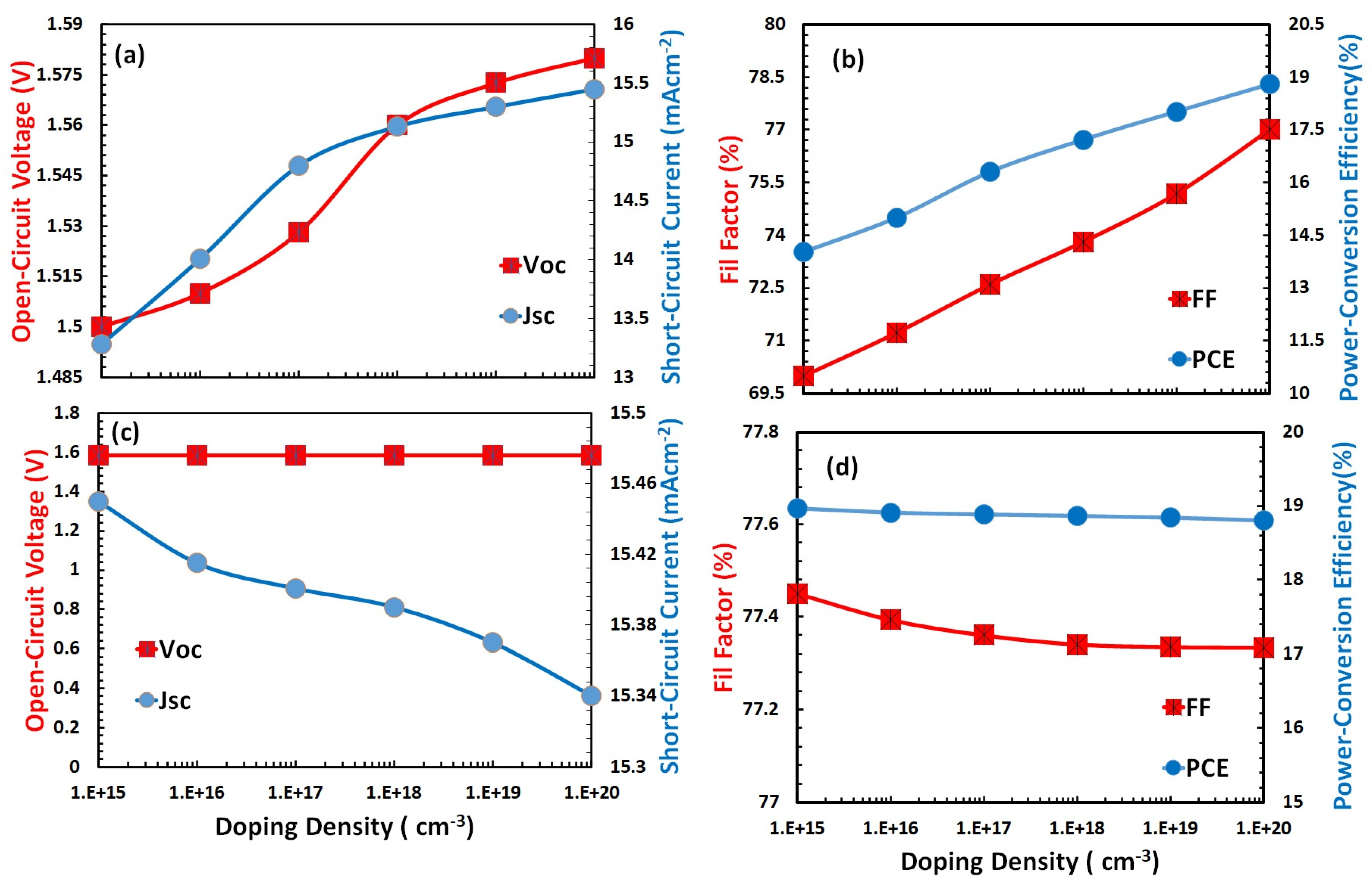
In the third phase of the simulation, the acceptor/donor doping density (Na/Nd) of the hole/electron transport layer was optimized by incorporating the optimized electron affinity and energy bandgap of both transport layers. Generally, the charge transportation and collection process of the hole and electron transport layer improves by doping, and it may be due to the reduction in both layers’ resistance for the formation of ohmic contacts to the respective electrodes [38,39,40]. It not only affects the charge transport and charge collection efficiency but also helps to manage the light-harvesting, and hence, it affects the overall device performance. At the same time, the doped hole and electron transport layers also cause an increase in the leakage current [41]; therefore, the doping optimization of both transport layers is very crucial for perovskite solar cells. Figure 5a,b shows the open-circuit voltage, short-circuit current, fill factor, and power conversion efficiency as a function of doping density of the hole transport layer, while Figure 5c,d show the open-circuit voltage, short-circuit current, fill factor, and power conversion efficiency as a function of doping density of the electron transport layer. The acceptor doping of the hole transport layer shows the increasing trend for all photovoltaic parameters, and especially PCE, and reaches the maximum (18.8%) at 1020 cm−3 for acceptor doping density. Correspondingly, donor doping of the electron transport layer shows a constant trend (approximately) for open-circuit voltage and PCE. Figure 5d shows that the PCE slightly increases and reaches a maximum (18.85%) at 1016 cm−3 and then follows a decreasing trend with a very low rate of PCE concerning donor doping density. Thus, it can be inferred from the above discussion that 1020/1016 cm−3 is the most optimum doping density of the hole and electron transport layer, respectively, for Cs2TiBr6-based perovskite solar cells.

3.4. Optimization of Thickness for Hole and Electron Transport Layer

In the second-to-last phase of the simulation, the thickness of the hole and electron transport layer was optimized for the Cs2TiBr6 solar cell by incorporating the already optimized electron affinity, energy bandgap, and doping density for both transport layers. The thickness of the transport layer is another very important factor required to optimize for efficient Cs2TiBr6-based perovskite solar cells [42,43].
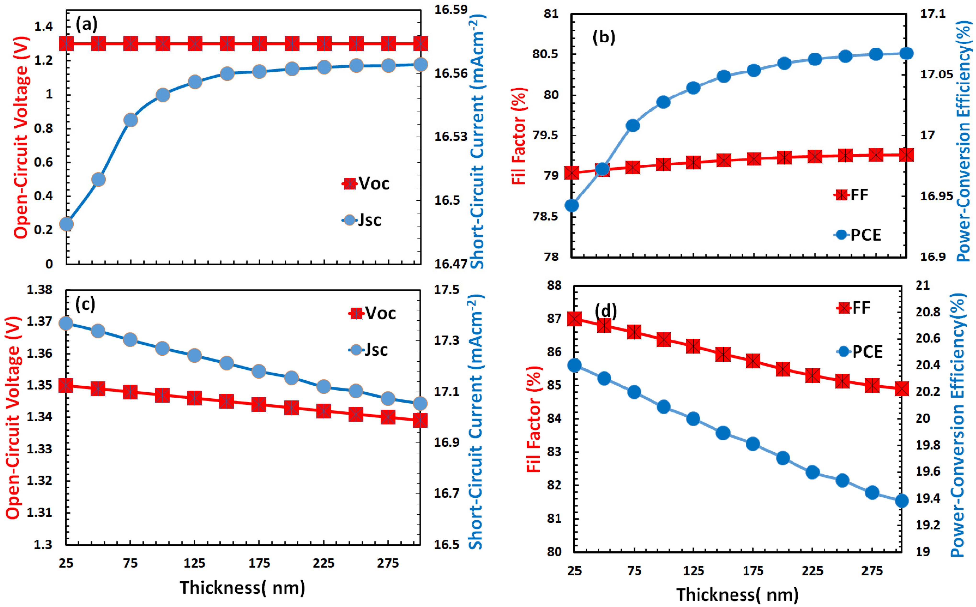
Thus, we first optimized the thickness of the hole (see Figure 6a,b) and then the electron transport layer (see Figure 6c,d) by using the optimized thickness of the hole transport layer. Figure 6a,b demonstrate that the open-circuit voltage, short-circuit current, fill factor, and power conversion efficiency increase as a function of hole transport layer thickness, but with different rates. The most important parameter PCE (see Figure 6b) increases (17.45%) up to a certain thickness (250 nm) and then becomes almost constant concerning HTL thickness. On the other hand, for the electron transport layer, the parameters such as open-circuit voltage, short-circuit current, fill factor, and power conversion efficiency linearly decreases as a function of a thickness (Figure 6c,d) and gives the maximum PCE (20.4%) at 25 nm. This thickness may be the result of the interplay optimization between the higher optical transmittance, efficient electron charge transport, and low leakage current with a small recombination rate for Cs2TiBr6-based perovskite solar cells.

3.5. Device Energy Level and Electric Field Distribution of ETL/Cs2TiBr6/HTL

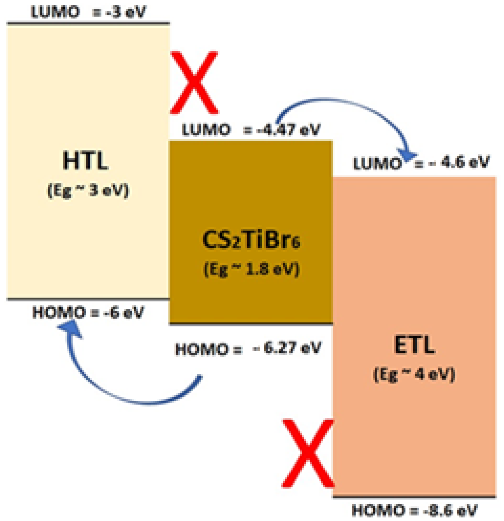
Figure 7 shows the electronic energy level diagram for the optimized ETL/Cs2TiBr6/HTL solar cell. The figure depicts that the HOMO (−6.0 eV) and LUMO (−3.0 eV) level of the hole transport layer support the efficient injection of the hole and blocking of an electron concerning the Cs2TiBr6 absorber layer. Similarly, the HOMO (−8.6 eV) and LUMO (−4.6 eV) level of the electron transport layer helps the efficient injection of electrons and blocking of the hole concerning the Cs2TiBr6 absorber layer. Therefore, the energy level alignment of the hole and electron transport layer with the Cs2TiBr6 perovskite absorber offers the basic electronic structure framework for highly efficient ETL/Cs2TiBr6/HTL-based perovskite solar cells.
The electric field distribution inside an electronic structure of a perovskite solar cell plays a very crucial role to define the overall carrier transport, recombination, and, hence, PCE of the perovskite solar cell. It is a direct function of the electrical nature of materials (HTL, ETL, and perovskite), doping density, band alignment, and interface parameters.
In our case, both HTL (1020 cm−3) and ETL (1016 cm−3) are unequally doped, while the thickness of the HTL (250 nm) is much larger than that of the ETL (25 nm). Therefore, an asymmetric electric field profile at HTL/Cs2TiBr6 and Cs2TiBr6/ETL is observed, as shown in Figure 8, which is responsible for the high open-circuit voltage and, hence, PCE. Thus, when photons fall on the Cs2TiBr6 layer, they are optically absorbed, and many excitons are generated with low binding energy, as well as high diffusion length. When these excitons reach their respective interfaces, they are dissociated into the free carrier due to the high interface electric field and are passed to either the HTL or ETL depending on the nature of the free carrier.

3.6. Selection of Hole and Electron Transport Layer

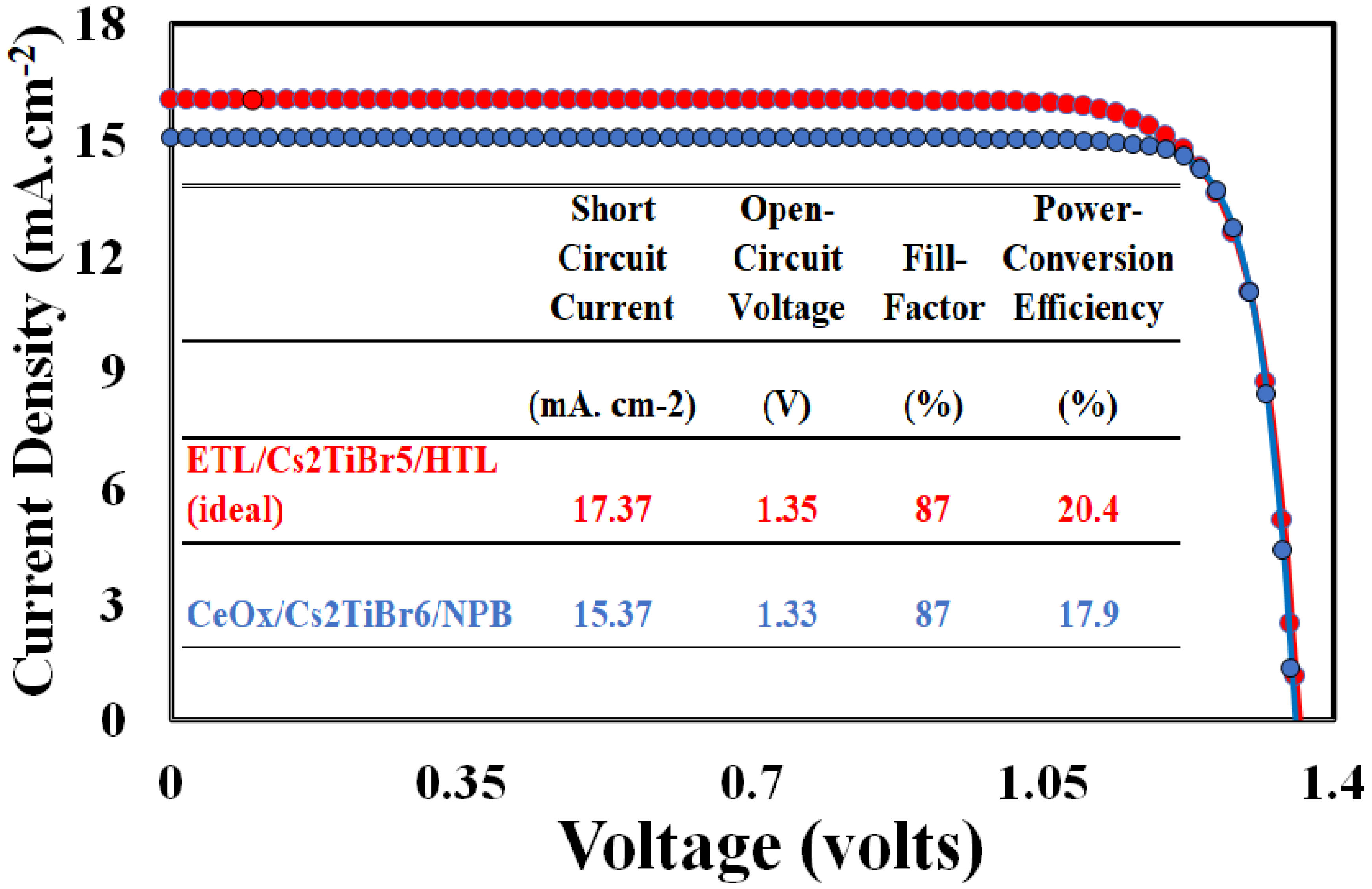
From the above discussion, it can be concluded that the proper selection of the hole transport layer with these physical parameters (electron affinity = −3 eV, energy band gap = 3 eV, Na = 1020 cm−3, and thickness =250 nm), as well as the use of an appropriate electron transport layer with physical parameters (electron affinity = −4.6 eV, energy band gap = 4 eV, Nd =1016 cm−3, and thickness = 25 nm), can give a maximum PCE up to 20.41% for the Cs2TiBr6-based perovskite solar cell. Unfortunately, not a single hole transport layer and electron transport layer material were available, as shown in Table 2 and Table 3, respectively, having a similar energy bandgap and electron affinity to fulfill the requirements for maximum PCE. Just for practical purposes, NPB as a hole transport layer material and CeOx as an electron transport layer materials were selected as their energy bandgap, and the activation energy is very close compared to the other materials listed in Table 2 and Table 3, respectively. Although SnO2 has a good electronic structure and shows more efficient performance as an ETL, the major issue with SnO2 as the ETL is that it offers some limitations for thin-film deposition and deteriorates at high temperatures during fabrication processes [44]. Therefore, we selected cerium oxide (CeOx) as the best ETL from Table 3. CeOx as an ETL has a very similar electronic structure compared to SnO2. It is a wide-bandgap semiconductor that has high conductivity, chemical and thermal stability, transparency in the visible range, and a good dielectric constant [28]. The physical parameters for NPB and CeOx were taken from the published results and are displayed in Table 5 [15,45,46]. The photovoltaic response of the proposed device as CeOx/Cs2TiBr6/NPB was simulated and compared with the photovoltaic response of an ideal ETL/Cs2TiBr6/HTL solar cell, and the output results are shown in Figure 9. The figure shows that the proposed solar cell performs well, and its PCE is ~17.9%, which is less than that of the ideal (PCE is 20.4%) solar cell. The simulated photovoltaic parameters such as open-circuit voltage, short circuit current, fill factor, and PCE of both solar cells are tabulated in the inset of Figure 9. The inset table depicts that the open-circuit voltage and fill factor of the proposed solar cell are nearly the same as those of the ideal one. The short-circuit current is the main parameter that causes a lowering of the PCE of the proposed solar cell compared to the ideal solar cell. The short-circuit current is directly dependent on the electronic structure of both transport layers [47]; therefore, it is highly recommended to tailor the electronic structure of both transport layers according to the simulation results for the highly efficient photovoltaic response. Different strategies are being reported in the literature to fabricate the hole transport and electron transport layers for the required electronic structure for efficient solar cells. Broadly speaking, these strategies can be classified into the following types: (i) chemical tailoring [48], (ii) solvent treatment [49], and (iii) using an interface buffer layer [50,51]. Anyone or a combination of these techniques can be applied successfully for the fabrication of hole and electron transport layers for efficient Cs2TiBr6-based perovskite solar cells.

4. Conclusions

Due to the toxic nature of methylammonium lead halide, many other lead-free perovskite materials have been heavily investigated and reported for photovoltaic applications. Among these, cesium-titanium (IV) bromide (Cs2TiBr6) is considered one of the best alternatives, but it still faces a lack of higher PCE due to the unavailability of the matched hole and electron transport layers. Therefore, for the highly efficient photovoltaic response, the physical parameters such as electron affinity, energy bandgap, doping density, and film thickness of ideal hole and electron transport layers were determined for the Cs2TiBr6-based solar cell through SCAPS-1D simulation. It was observed that the proper hole transport layer (electron affinity = −3 eV, energy band gap = 3 eV, Na =1020 cm−3, and thickness = 250 nm), as well as using the appropriate electron transport layer (electron affinity = −4.6 eV, energy band gap = 4 eV, Nd =1016 cm−3, and thickness = 25 nm), can give a maximum PCE up to 20.41% for Cs2TiBr6-based perovskite solar cells. Unfortunately, not a single hole and electron transport material with the required electronic structure was found. However, NPB and CeOx were selected as hole and electron transport layers, respectively, based on the closed electronic structure compared to the simulation results, and the simulated maximum PCE was found as ~17.9% for the CeOx/Cs2TiBr6/NPB solar cell. We believe that the outcome of this study will help the development and fabrication of highly efficient lead-free perovskite solar cells.

Funding

Deputyship for Research & Innovation, Ministry of education in Saudi Arabia for funding this research work through project number 20-UQ-IF-P2-001.

Acknowledgments

The author extends their appreciation to the Deputyship for Research & innovation, Ministry of education in Saudi Arabia for funding this research work through the project number 20-UQU-IF-P2-001.

Conflicts of Interest

The author declares that there are no conflict of interest to report regarding the pre-sent study.

References

  1. Kabir, E.; Kumar, P.; Kumar, S.; Adelodun, A.A.; Kim, K.-H. Solar energy: Potential and future prospects. Renew. Sustain. Energy Rev. 2018, 82, 894–900. [Google Scholar] [CrossRef]
  2. Nazeeruddin, M.K. Twenty-five years of low-cost solar cells. Nature 2016, 538, 463–464. [Google Scholar] [CrossRef] [PubMed]
  3. Karimov, K.S.; Ahmed, M.; Moiz, S.; Fedorov, M. Temperature-dependent properties of organic-on-inorganic Ag/p-CuPc/n-GaAs/Ag photoelectric cell. Sol. Energy Mater. Sol. Cells 2005, 87, 61–75. [Google Scholar] [CrossRef]
  4. Green, M.A. The path to 25% silicon solar cell efficiency: History of silicon cell evolution. Prog. Photovolt. Res. Appl. 2009, 17, 183–189. [Google Scholar] [CrossRef]
  5. Pizzini, S. Towards solar grade silicon: Challenges and benefits for low cost photovoltaics. Sol. Energy Mater. Sol. Cells 2010, 94, 1528–1533. [Google Scholar] [CrossRef]
  6. Kim, G.-H.; Kim, D.S. Development of perovskite solar cells with >25% conversion efficiency. Joule 2021, 5, 1033–1035. [Google Scholar] [CrossRef]
  7. Babayigit, A.; Ethirajan, A.; Muller, M.; Conings, B. Toxicity of organometal halide perovskite solar cells. Nat. Mater. 2016, 15, 247–251. [Google Scholar] [CrossRef]
  8. Giustino, F.; Snaith, H.J. Toward Lead-Free Perovskite Solar Cells. ACS Energy Lett. 2016, 1, 1233–1240. [Google Scholar] [CrossRef] [Green Version]
  9. Chen, M.; Ju, M.-G.; Carl, A.; Zong, Y.; Grimm, R.L.; Gu, J.; Zeng, X.C.; Zhou, Y.; Padture, N.P. Cesium Titanium(IV) Bromide Thin Films Based Stable Lead-free Perovskite Solar Cells. Joule 2018, 2, 558–570. [Google Scholar] [CrossRef] [Green Version]
  10. Ju, M.-G.; Chen, M.; Zhou, Y.; Garces, H.F.; Dai, J.; Ma, L.; Padture, N.P.; Zeng, X.C. Earth-Abundant Nontoxic Titanium(IV)-based Vacancy-Ordered Double Perovskite Halides with Tunable 1.0 to 1.8 eV Bandgaps for Photovoltaic Applications. ACS Energy Lett. 2018, 3, 297–304. [Google Scholar] [CrossRef]
  11. Pecunia, V.; Occhipinti, L.G.; Chakraborty, A.; Pan, Y.; Peng, Y. Lead-free halide perovskite photovoltaics: Challenges, open questions, and opportunities. APL Mater. 2020, 8, 100901. [Google Scholar] [CrossRef]
  12. Grandhi, G.; Matuhina, A.; Liu, M.; Annurakshita, S.; Ali-Löytty, H.; Bautista, G.; Vivo, P. Lead-Free Cesium Titanium Bromide Double Perovskite Nanocrystals. Nanomaterials 2021, 11, 1458. [Google Scholar] [CrossRef]
  13. Chakraborty, K.; Choudhury, M.G.; Paul, S. Numerical study of Cs2TiX6 (X = Br, I, F and Cl) based perovskite solar cell using SCAPS-1D device simulation. Sol. Energy 2019, 194, 886–892. [Google Scholar] [CrossRef]
  14. Jani, R.; Islam, T.; Al Amin, S.M.; Sami, S.U.; Shorowordi, K.M.; Hossain, M.I.; Chowdhury, S.; Nishat, S.S.; Ahmed, S. Exploring solar cell performance of inorganic Cs2TiBr6 halide double perovskite: A numerical study. Superlattices Microstruct. 2020, 146, 106652. [Google Scholar] [CrossRef]
  15. Moiz, S.; Alahmadi, A. Design of Dopant and Lead-Free Novel Perovskite Solar Cell for 16.85% Efficiency. Polymers 2021, 13, 2110. [Google Scholar] [CrossRef] [PubMed]
  16. Moiz, S.A.; Alahmadi, A.N.M.; Aljohani, A.J. Design of a Novel Lead-Free Perovskite Solar Cell for 17.83% Efficiency. IEEE Access 2021, 9, 54254–54263. [Google Scholar] [CrossRef]
  17. Qiao, L.; Fang, W.-H.; Long, R. Dopant Control of Electron–Hole Recombination in Cesium–Titanium Halide Double Perovskite by Time Domain Ab Initio Simulation: Codoping Supersedes Monodoping. J. Phys. Chem. Lett. 2018, 9, 6907–6914. [Google Scholar] [CrossRef] [PubMed]
  18. Park, S.M.; Mazza, S.M.; Liang, Z.; Abtahi, A.; Boehm, A.M.; Parkin, S.R.; Anthony, J.E.; Graham, K.R. Processing Dependent Influence of the Hole Transport Layer Ionization Energy on Methylammonium Lead Iodide Perovskite Photovoltaics. ACS Appl. Mater. Interfaces 2018, 10, 15548–15557. [Google Scholar] [CrossRef] [PubMed]
  19. Lopez-Varo, P.; Jiménez-Tejada, J.A.; García-Rosell, M.; Ravishankar, S.; Garcia-Belmonte, G.; Bisquert, J.; Almora, O. Device Physics of Hybrid Perovskite Solar cells: Theory and Experiment. Adv. Energy Mater. 2018, 8, 1702772. [Google Scholar] [CrossRef]
  20. Yin, W.-J.; Shi, T.; Yan, Y. Unusual defect physics in CH3NH3PbI3 perovskite solar cell absorber. Appl. Phys. Lett. 2014, 104, 063903. [Google Scholar] [CrossRef]
  21. Moiz, S.A.; Alahmadi, A.N.M.; Aljohani, A.J. Design of Silicon Nanowire Array for PEDOT:PSS-Silicon Nanowire-Based Hybrid Solar Cell. Energies 2020, 13, 3797. [Google Scholar] [CrossRef]
  22. Moiz, S.A.; Nahhas, A.; Um, H.-D.; Jee, S.-W.; Cho, H.K.; Kim, S.-W.; Lee, J.-H. A stamped PEDOT:PSS–silicon nanowire hybrid solar cell. Nanotechnology 2012, 23, 145401. [Google Scholar] [CrossRef]
  23. Verschraegen, J.; Burgelman, M. Numerical modeling of intra-band tunneling for heterojunction solar cells in scaps. Thin Solid Films 2007, 515, 6276–6279. [Google Scholar] [CrossRef]
  24. Burgelman, M.; Verschraegen, J.; Degrave, S.; Nollet, P. Modeling thin-film PV devices. Prog. Photovolt. Res. Appl. 2004, 12, 143–153. [Google Scholar] [CrossRef]
  25. Xiao, Z.; Yuan, Y.; Wang, Q.; Shao, Y.; Bai, Y.; Deng, Y.; Dong, Q.; Hu, M.; Bi, C.; Huang, J. Thin-film semiconductor perspective of organometal trihalide perovskite materials for high-efficiency solar cells. Mater. Sci. Eng. R Rep. 2016, 101, 1–38. [Google Scholar] [CrossRef] [Green Version]
  26. Burgelman, M.; Decock, K.; Khelifi, S.; Abass, A. Advanced electrical simulation of thin film solar cells. Thin Solid Films 2013, 535, 296–301. [Google Scholar] [CrossRef]
  27. Liu, T.; Chen, K.; Hu, Q.; Zhu, R.; Gong, Q. Inverted Perovskite Solar Cells: Progresses and Perspectives. Adv. Energy Mater. 2016, 6, 1600457. [Google Scholar] [CrossRef]
  28. Wang, X.; Deng, L.-L.; Wang, L.-Y.; Dai, S.-M.; Xing, Z.; Zhan, X.-X.; Lu, X.-Z.; Xie, S.-Y.; Huang, R.-B.; Zheng, L.-S. Cerium oxide standing out as an electron transport layer for efficient and stable perovskite solar cells processed at low temperature. J. Mater. Chem. A 2016, 5, 1706–1712. [Google Scholar] [CrossRef]
  29. Azri, F.; Meftah, A.; Sengouga, N.; Meftah, A. Electron and hole transport layers optimization by numerical simulation of a perovskite solar cell. Sol. Energy 2019, 181, 372–378. [Google Scholar] [CrossRef]
  30. Lin, P.; Lin, L.; Yu, J.; Cheng, S.; Lu, P.; Zheng, Q. Numerical Simulation of Cu2ZnSnS4 Based Solar Cells with In2S3 Buffer Layers by SCAPS-1D. J. Appl. Sci. Eng. 2014, 17, 383–390. [Google Scholar] [CrossRef]
  31. Ahmed, S.; Jannat, F.; Khan, A.K.; Alim, M.A. Numerical development of eco-friendly Cs2TiBr6 based perovskite solar cell with all-inorganic charge transport materials via SCAPS-1D. Optik 2020, 225, 165765. [Google Scholar] [CrossRef]
  32. Lam, N.D.; Nguyen, D.L. Modelling and numerical analysis of ZnO/CuO/Cu2O heterojunction solar cell using SCAPS. Eng. Res. Express 2020, 2, 025033. [Google Scholar] [CrossRef]
  33. Hima, A.; Lakhdar, N. Enhancement of efficiency and stability of CH3NH3GeI3 solar cells with CuSbS2. Opt. Mater. 2019, 99, 109607. [Google Scholar] [CrossRef]
  34. Jayan, K.D. Enhancement of efficiency of (FA)2BiCuI6 based perovskite solar cells with inorganic transport layers. Opt. Mater. 2021, 122, 111671. [Google Scholar] [CrossRef]
  35. Karthick, S.; Bouclé, J.; Velumani, S. Effect of bismuth iodide (BiI3) interfacial layer with different HTL’s in FAPI based perovskite solar cell—SCAPS—1D study. Sol. Energy 2021, 218, 157–168. [Google Scholar] [CrossRef]
  36. Pham, D.P.; Lee, S.; Kim, Y.; Yi, J. Band-offset reduction for effective hole carrier collection in bifacial silicon heterojunction solar cells. J. Phys. Chem. Solids 2021, 154, 110059. [Google Scholar] [CrossRef]
  37. Um, H.-D.; Moiz, S.A.; Park, K.-T.; Jung, J.-Y.; Jee, S.-W.; Ahn, C.H.; Kim, D.-W.; Cho, H.K.; Lee, J.-H. Highly selective spectral response with enhanced responsivity of n-ZnO/p-Si radial heterojunction nanowire photodiodes. Appl. Phys. Lett. 2011, 98, 033102. [Google Scholar] [CrossRef]
  38. Subair, R.; Di Girolamo, D.; Bodik, M.; Nadazdy, V.; Li, B.; Nadazdy, P.; Markovic, Z.; Benkovicova, M.; Chlpik, J.; Kotlar, M.; et al. Effect of the doping of PC61BM electron transport layer with carbon nanodots on the performance of inverted planar MAPbI3 perovskite solar cells. Sol. Energy 2019, 189, 426–434. [Google Scholar] [CrossRef]
  39. Gotanda, T.; Kimata, H.; Xue, D.; Asai, H.; Shimazaki, A.; Wakamiya, A.; Marumoto, K. Direct observation of charge transfer at the interface between PEDOT:PSS and perovskite layers. Appl. Phys. Express 2019, 12, 041002. [Google Scholar] [CrossRef]
  40. Moiz, S.A.; Khan, I.A.; Younis, W.A.; Masud, M.I.; Ismail, Y.; Khawaja, Y.M. Solvent induced charge transport mechanism for conducting polymer at higher temperature. Mater. Res. Express 2020, 7, 095304. [Google Scholar] [CrossRef]
  41. Schloemer, T.H.; Christians, J.A.; Luther, J.M.; Sellinger, A. Doping strategies for small molecule organic hole-transport materials: Impacts on perovskite solar cell performance and stability. Chem. Sci. 2019, 10, 1904–1935. [Google Scholar] [CrossRef] [PubMed] [Green Version]
  42. Marinova, N.; Tress, W.; Humphry-Baker, R.; Dar, M.I.; Bojinov, V.; Zakeeruddin, S.M.; Nazeeruddin, M.K.; Grätzel, M. Light Harvesting and Charge Recombination in CH3NH3PbI3 Perovskite Solar Cells Studied by Hole Transport Layer Thickness Variation. ACS Nano 2015, 9, 4200–4209. [Google Scholar] [CrossRef] [PubMed]
  43. Kim, G.-W.; Shinde, D.V.; Park, T. Thickness of the hole transport layer in perovskite solar cells: Performance versus reproducibility. RSC Adv. 2015, 5, 99356–99360. [Google Scholar] [CrossRef]
  44. Xiong, L.; Guo, Y.; Wen, J.; Liu, H.; Yang, G.; Qin, P.; Fang, G. Review on the Application of SnO2 in Perovskite Solar Cells. Adv. Funct. Mater. 2018, 28, 1802757. [Google Scholar] [CrossRef]
  45. Karimi, E.; Ghorashi, S. Investigation of the influence of different hole-transporting materials on the performance of perovskite solar cells. Optik 2017, 130, 650–658. [Google Scholar] [CrossRef]
  46. Ahmmed, S.; Karim, A.; Rahman, H.; Aktar, A.; Islam, R.; Islam, A.; Ismail, A.B.M. Performance analysis of lead-free CsBi3I10-based perovskite solar cell through the numerical calculation. Sol. Energy 2021, 226, 54–63. [Google Scholar] [CrossRef]
  47. Wu, M.-C.; Chan, S.-H.; Jao, M.-H.; Su, W.-F. Enhanced short-circuit current density of perovskite solar cells using Zn-doped TiO2 as electron transport layer. Sol. Energy Mater. Sol. Cells 2016, 157, 447–453. [Google Scholar] [CrossRef]
  48. Schulz, P.; Kelly, L.L.; Winget, P.; Li, H.; Kim, H.; Ndione, P.F.; Sigdel, A.K.; Berry, J.J.; Graham, S.; Brédas, J.-L.; et al. Tailoring Electron-Transfer Barriers for Zinc Oxide/C60Fullerene Interfaces. Adv. Funct. Mater. 2014, 24, 7381–7389. [Google Scholar] [CrossRef]
  49. Park, Y.I.; Kuo, C.-Y.; Martinez, J.S.; Park, Y.-S.; Postupna, O.; Zhugayevych, A.; Kim, S.; Park, J.; Tretiak, S.; Wang, H.-L. Tailored Electronic Structure and Optical Properties of Conjugated Systems through Aggregates and Dipole–Dipole Interactions. ACS Appl. Mater. Interfaces 2013, 5, 4685–4695. [Google Scholar] [CrossRef]
  50. Moiz, S.; Alahmadi, A.; Karimov, K. Improved organic solar cell by incorporating silver nanoparticles embedded polyaniline as buffer layer. Solid-State Electron. 2019, 163, 107658. [Google Scholar] [CrossRef]
  51. Zheng, Z.; Wang, R.; Yao, H.; Xie, S.; Zhang, Y.; Hou, J.; Zhou, H.; Tang, Z. Polyamino acid interlayer facilitates electron extraction in narrow band gap fullerene-free organic solar cells with an outstanding short-circuit current. Nano Energy 2018, 50, 169–175. [Google Scholar] [CrossRef]
Figure 1. Schematic cross-section of perovskite solar cell, where absorber (Cs2TiBr6) is sandwiched between hole transport layer (HTL) and an electron transport layer (ETL).
Photonics 09 00023 g001
Figure 2. Flowchart used in this study to estimate the ideal hole transport layer (HTL) and electron transport layer (ETL) properties for Cs2TiBr6-based perovskite solar cell.
Photonics 09 00023 g002
Figure 3. (a) Open-circuit voltage, short-circuit current, (b) fill factor, and power conversion efficiency of hole transport layer as a function of electron affinity. (c) Open-circuit voltage, short-circuit current, (d) fill factor, and power conversion efficiency of electron transport layer as a function of electron affinity for Cs2TiBr6-based solar cell.
Photonics 09 00023 g003
Figure 4. (a) Open-circuit voltage, short-circuit current, (b) fill factor, and power conversion efficiency of HTL as a function of electron affinity. (c) Open-circuit voltage, short-circuit current, (d) fill factor, and power conversion efficiency of ETL as a function of energy bandgap for Cs2TiBr6-based solar cell.
Photonics 09 00023 g004
Figure 5. (a) Open-circuit voltage, short-circuit current, (b) fill factor, and power conversion efficiency of HTL as a function of electron affinity. (c) Open-circuit voltage, short-circuit current, (d) fill factor, and power conversion efficiency of ETL as a function of doping density for Cs2TiBr6-based solar cell.
Photonics 09 00023 g005
Figure 6. (a) Open-circuit voltage, short-circuit current, (b) fill factor, and power conversion efficiency of HTL as a function of electron affinity. (c) Open-circuit voltage, short-circuit current, (d) fill factor, and power conversion efficiency of ETL as a function of film thickness for Cs2TiBr6-based solar cell.
Photonics 09 00023 g006
Figure 7. Energy level alignment for Cs2TiBr6 cell with highly suitable band structure of hole transport and electron transport layer for an efficient photovoltaic response.
Photonics 09 00023 g007
Figure 8. Electric field distribution inside ETL (25 nm)/Cs2TiBr6 (200 nm)/HTL (250 nm) solar cell.
Photonics 09 00023 g008
Figure 9. Photo current-voltage response of ETL/Cs2TiBr6/HTL and CeOx/Cs2TiBr6/NPB solar cells. The inset lists the photovoltaic parameters such as short-circuit current, open-circuit voltage, fill factor, and PCE for both solar cells.
Photonics 09 00023 g009
Table 1. Summary of the published photovoltaic responses of Cs2TiBr6-based perovskite solar cell.
YearDeviceStudyHTLETLJscVocFFPCERef
2018FTO/TiO2/Cs2TiBr6/P3HT/AuExperimentalP3HTTiO2 /C603.870.8959.52.15[9]
2018FTO/TiO2/C60/Cs2TiBr6/P3HT/AuExperimentalP3HTTiO25.750.9954.93.12[9]
2019CuSCN/ Cs2TiBr6/CdS/SiSimulationCuSCNCdS8.96.68[13]
2020Glass/FTO/TiO2/Cs2TiBr6/Cu2O/ASimulationCu2OTiO225.821.151.714.68[14]
2021Ag/BCP/PCBM/Cs2TiBr6/NPB/ITOSimulationNPBBCP/PCBM16.661.2978.116.85[15]
2021Au/PEDOT:PSS/Cs2TiBr6/TiO2/AZO SimulationPEDOT:PSSTiO218.21.3871%17.83[16]
Table 2. Energy bandgap and electron affinity for commonly reported hole transport layer materials.
Transport Layer MaterialEnergy Band Gap (Eg, eV)Electron Affinity (EA, eV)Reference
Cu2O2.173.2[13]
Spiro-OMeTAD3.22.1[28]
PEDOT:PSS1.63.5[16]
NPB32.4[15]
P3HT1.853.1[29]
CuSCN3.41.9[29]
NiO3.61.46[28]
CZTS1.54.5[30]
CuI2.982.1[29,31]
CuO1.34[32]
MoO332.5[29]
NiO3.81.46[29]
CuSbS21.584.2[33]
Table 3. Energy bandgap and electron affinity for commonly reported electron transport layer materials.
Transport Layer MaterialEnergy Band Gap (Eg, eV)Electron Affinity (EA, eV)Reference
TiO23.264.26[13,16]
ZnO:Al3.34.6[16,30]
IGZO3.054.16[29]
ZnO 3.24.26[34]
SnO23.54[35]
In2S32.84.7[30]
CeOx3.54[28]
PCBM1.93.9[15]
BCP3.53.7[15]
CdS2.41.8[31]
Eg: min: 1.9, max: 3.5, median: 3.23.
Table 4. Physical parameters of Cs2TiBr6 and hole and electron transport layer used in the simulation.
Physical ParametersSymbolUnitHTLCs2TiB6ETL
ThicknessThnm250200250
Energy Band GapEgeV21.82
Electron AffinityχeV4.54.474
Dielectric Permittivity (Relative)ε-101010
Effective Density of States at Valence BandNVcm−31 × 10206 × 10191 × 1019
Effective Density of States at Conduction BandNCcm−31 × 10202 × 10191 × 1019
Hole Thermal VelocityVecm/s1 × 1071 × 1071 × 107
electron Thermal VelocityVhcm/s1 × 1071 × 1071 × 107
Electron Mobilityμecm2/V.s 0.014.41
Hole Mobilityμhcm2/V.s 0.12.50.1
Uniform Shallow Donor DopingNdcm−301 × 10191 × 1018
Uniform Shallow Acceptor DopingNacm−31 × 10181 × 10190
Defect DensityNtcm−31 × 10151 × 10151 × 1015
References Random[9,10,13]Random
Table 5. Physical parameters of Cs2TiBr6 and NPB (HTL) and CeOx (ETL) were used in the simulation. Both NPB and CeOx are selected based on the closeness of the energy bandgap and electron affinity with the simulation results.
Physical ParametersSymbolUnitNPB (HTL)Cs2TiB6CeOx (ETL)
Thickness Thnm25015025
Energy Band GapEgeV2.41.83.5
Electron AffinityχeV34.474.4
Dielectric Permittivity (Relative)ε-3109
Effective Density of States at Valence BandNVcm−31 × 10216 × 10191x 1020
Effective Density of States at Conduction BandNCcm−31 × 10212 × 10192 × 1021
Hole Thermal VelocityVecm/s1 × 1071 × 1071 × 107
electron Thermal VelocityVhcm/s1 × 1071 × 1071 × 107
Electron Mobilityμecm2/V.s 6 × 10−64.4100
Hole Mobilityμhcm2/V.s 6.1 × 10−42.525
Uniform Shallow Donor DopingNdcm−301 × 10171 × 1016
Uniform Shallow Acceptor DopingNacm−31 × 10201 × 10170
Defect DensityNtcm−31 × 10141 × 10151 × 1015
References [15,45][9,10,13,14][46]
Publisher’s Note: MDPI stays neutral with regard to jurisdictional claims in published maps and institutional affiliations.