Review

Transmission and Generation of Orbital ANGULAR Momentum Modes in Optical Fibers

1
Photonics Research Center, Department of Electronic and Information Engineering, The Hong Kong Polytechnic University, Hong Kong 999077, China
2
Shenzhen Research Institute, The Hong Kong Polytechnic University, Shenzhen 518057, China
3
Department of Electronic Engineering, School of Information Science and Technology, Jinan University, Guangzhou 510632, China
4
State Key Laboratory Optoelectronic Materials and Technologies, School of Electronics and Information Technology, Sun Yat-sen University, Guangzhou 510275, China
*
Author to whom correspondence should be addressed.
Photonics 2021, 8(7), 246; https://doi.org/10.3390/photonics8070246
Submission received: 24 May 2021 / Revised: 20 June 2021 / Accepted: 22 June 2021 / Published: 30 June 2021
(This article belongs to the Special Issue Novel Specialty Optical Fibers and Applications)

Abstract

:
The orbital angular momentum (OAM) of light provides a new degree of freedom for carrying information. The stable propagation and generation of OAM modes are necessary for the fields of OAM-based optical communications and microscopies. In this review, we focus on discussing the novel fibers that are suitable for stable OAM mode transmission and conversion. The fundamental theory of fiber modes is introduced first. Then, recent progress on a multitude of fiber designs that can stably guide or generate OAM modes is reviewed. Currently, the mode crosstalk is regarded as the main issue that damages OAM mode stability. Therefore, the coupled-mode theory and coupled-power power theory are introduced to analyze OAM modes crosstalk. Finally, the challenges and prospects of the applications of OAM fibers are discussed.

1. Introduction

A photon can carry spin angular momentum (SAM) and orbital angular momentum (OAM). The SAM of light is associated with the spin of a photon, and it can be characterized as the circular polarization of a light beam [1]. The values of SAM are ± per photon, which correspond to left- and right-handed circularly polarized states, respectively. Different from the SAM, the OAM of light originates from the azimuthal phase distribution at the wave front [2]. In 1992, Allen et al. first recognized that a light beam having a helical phase exp ( i l ϕ ) can carry OAM with the value l per photon [3]. After this groundbreaking work, detailed studies on optical OAM were constantly carried out [4] and have given rise to developments in many application areas including trapping and guiding atoms with optical OAM [5,6,7], OAM states’ entanglement [8], high-dimensional cryptography [9], vortex beam assisted microscopy [10,11]. and optical communications [12,13,14,15].
At present, the high growth rate of the demand for data transmission capacity leads to a huge challenge for the optical communication community. Space-division multiplexing (SDM) is considered as an effective method to solve the problem of capacity crunch in the f long term [16]. It is obvious that, by using multiple space channels, the nominal data transmission capacity can be increased greatly. Fortunately, the optical OAM provides a new degree of physical dimension for SDM [13,14]. OAM modes can be generated by using spatial light modulators (SLMs) [12], spiral phase plates [17], log-polar mapping [18,19], angular gratings [20], fiber couplers [21,22], and fiber gratings [23,24,25,26,27]. These methods provide various choices for loading information onto OAM beams. In addition, Dammann vortex gratings give a feasible way for the wide-range detection of OAM modes [28] and for the multiplexing and demultiplexing of massive OAM channels [29]. In addition, the technique of multi-plane light conversion provides another effective way to multiplex and demultiplex OAM modes [30,31]. However, the stable long-distance transmission of massive OAM modes is still an open issue. In the case of free-space-optics (FSO) data transmission, the atmospheric turbulence can cause the fluctuation of the refractive index of air, which damages the intensity profile and the transverse phase structure of OAM modes [32]. In addition, the diffraction of OAM beams limits the FSO data transmission in long-distance situations. Another way for OAM mode propagation is using optical fiber. The OAM modes form a set of orthogonal bases, which is equivalent to the basis of vector modes in optical fibers. Because of the orthogonality, each OAM mode can carry information independently under ideal conditions. However, the fiber defects introduced in the fabrication and the irregular bending in the application will break the orthogonal condition of fiber modes and cause inter-mode crosstalk [33]. Therefore, the novel designs to reduce the crosstalk of OAM modes in optical fiber and the signal processing algorithm to compensate the overall crosstalk at the receiving end attract extensive attention.
In 2009, Ramachandran et al. first demonstrated a kind of ring-core fiber (RCF) in which the first-order vector modes can be transmitted with outstanding stability [34]. Later, a fiber with ring-core structure was used to transmit OAM modes, achieving terabit-scale SDM [14]. To further increase the stability of OAM modes, a kind of air-hole ring-core fiber (AH-RCF) was proposed and tested [35]. It shows good ability to conserve OAM modes even in the presence of strong bend perturbations. Using this kind of fiber, a 13.4 km OAM state transmission was demonstrated [36]. At the same time, a kind of ring-core photonic crystal fiber (RC-PCF) was designed for OAM mode transmission with ultra-low confinement loss and wide bandwidth [37]. In addition, Wong et al. found that helically twisted PCF can preserve the chirality of OAM modes [38]. These works provide good references for the long-distance transmission of OAM modes.
Our group also attaches great importance to the study of OAM-related optical fibers and fiber devices. A kind of microstructure RCF employing negative curvature cladding structures was proposed and fabricated [39,40]. Under experimental test, it showed low transmission loss of the first-order OAM modes with the value of 0.095 dB / m . In addition, all-fiber OAM generators based on asymmetric long-period fiber gratings (LPFGs) were fabricated. Experiments demonstrated that the generation efficiencies from the fundamental mode to second- and third-order OAM modes were 99.7 % [24] and 99.8 % [25], respectively. Furthermore, we are currently doing the simulation and fabrication of low crosstalk muli-ring-core fibers (MRCFs) for dense SDM.
This paper introduces the fiber-guided OAM modes from the principle of fiber mode theory and highlight the advances in design, fabrication, and application of OAM fibers including conventional solid optical fibers and microstructure optical fibers. The crosstalk of OAM modes under fiber deformations is discussed using coupled-mode theory [33] and coupled-power theory [41]. Additionally, we also review the progress of all-fiber OAM generation techniques. The technical challenges and application prospects of OAM fibers are discussed at the end.

2. OAM Modes in Regular Solid Optical Fibers

Optical fiber is a kind of circularly symmetric waveguide; thus, the electric and magnetic fields of eigenmodes can be expressed in the form of separating variables as
E ( r , ϕ , z ) = [ r ^ e r ( r ) cos ( v ϕ + ϕ 0 ) ϕ ^ e ϕ ( r ) sin ( v ϕ + ϕ 0 ) + z ^ e z ( r ) cos ( v ϕ + ϕ 0 ) ] exp ( i β z ) ,
H ( r , ϕ , z ) = [ r ^ h r ( r ) sin ( v ϕ + ϕ 0 ) + ϕ ^ h ϕ ( r ) cos ( v ϕ + ϕ 0 ) + z ^ h z ( r ) sin ( v ϕ + ϕ 0 ) ] exp ( i β z ) ,
where r ^ , ϕ ^ , and z ^ are unit vectors in the radial, angular, and longitudinal directions of an optical fiber. β is the propagation constant. Shown by the vector mode category in Figure 1, the fiber eigenmodes can be classified into HE l , v , EH l , v , TE 0 , v , and TM 0 , v modes [42], where l and v (= 1,2,3 ) represent azimuthal order and radial order of modes, respectively. Commonly, the constant phase ϕ 0 in Equation (1) is chosen as 0 or π / 2 to represent even or odd polarization state. The superposition of even and odd states of each HE and EH mode with a ± π / 2 phase difference can form OAM modes as [43]
OAM ± ( l 1 ) , v ± = HE l , v e ± i HE l , v o ,
OAM ± ( l + 1 ) , v = EH l , v e ± i EH l , v o ,
where “ e ” and “ o ” represent even and odd polarization states and the superscripts “+” and “−” correspond to left- and right-handed circular polarization, respectively. The elements l 1 and l + 1 are the absolute values of OAM topological charge. When l = 1 , the HE modes can only form a circularly polarized state without carrying OAM. In addition, because TE 0 , v and TM 0 , v modes are intrinsically non-degenerate [43], their relative phase difference will vary periodically with propagation; consequently, they can not form stable OAM modes. Therefore, the synthetic modes constructed by TE 0 , v and TM 0 , v are excluded from the category of OAM modes in Figure 1. When a fiber is in the weakly guiding condition, the effective index difference ( Δ n eff ) between the near-degenerate modes are too small to be distinguished. In this case, mode coupling can easily happen, and the superposition of near-degenerate vector modes can form linearly polarized (LP) states, which is shown by the category in the left side of Figure 1. Mathematically, the LP modes are the solutions of scalar Helmholtz equations under the weakly guiding approximation. Since the polarization effects at the refractive index step are ignored, all the polarization states in the same LP mode group have an identical effective index ( n eff ).

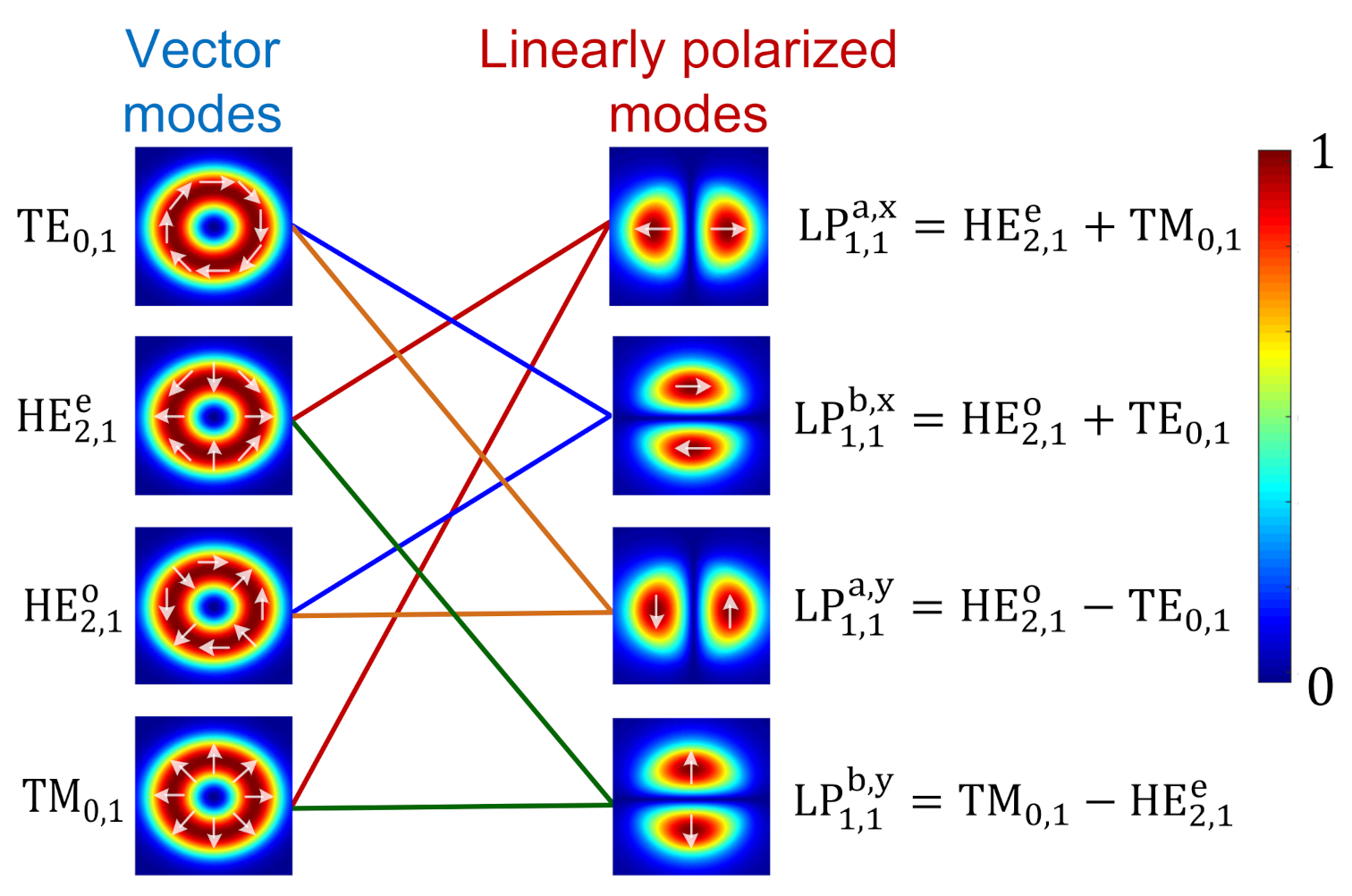
2.1. OAM Modes in Circular-Core Fibers

The refractive index profile of a conventional step-index circular-core fiber (SI-CCF) is shown in Figure 2a. The fiber guiding condition is determined by the values of core refractive index ( n co ) and core radius ( r co ). Vector modes in the SI-CCF can be obtained by solving Helmholtz equations with the tangential continuous boundary conditions. Using Equation (2), the OAM modes having a helical wave-front phase can be formed by the superposition of vector modes. As an example, Figure 1 shows the wave-front phase and circularly polarized chirality of OAM ± 1 , 1 ± , OAM ± 2 , 1 ± and OAM ± 2 , 1 ; these modes are formed by HE 2 , 1 e / o , HE 3 , 1 e / o , and EH 1 , 1 e / o , respectively. The variation of n eff for vector modes versus fiber core radius is shown in Figure 2b. We can see that radial higher-order modes (HOMs) such as HE 1 , 2 , TE 0 , 2 , and TM 0 , 2 will by accompanied by the azimuthal HOMs. These undesired radial HOMs will increase the complexity of mode coupling and decrease the stability of OAM modes in transmission.
In addition, near-degenerate vector modes such as TE 0 , 1 , HE 2 , 1 , and TM 0 , 1 have almost the same n eff . The Δ n eff around 1 × 10 5 is too small to avoid the accidental phase matching between the near-degenerate modes. Referring to the experiment of polarization maintaining fibers, the Δ n eff should be greater than 1 × 10 4 to maintain a polarization state of the HE 1 , 1 mode in length scales exceeding 100 m [43]. Thus, in practice, the fiber index profile deformation and fiber bending can easily cause mode coupling between the near-degenerate vector modes or OAM modes. The superposition of near-degenerate vector modes can form LP modes. As shown in Figure 3, because of strong mode coupling, the intensity patterns of LP modes can be observed at the fiber output end, even though the inputs are true vector modes.
Graded-index circular-core fibers (GI-CCFs) were also studied for OAM mode transmission [44,45,46]. Because the gradient of the graded-index profile is much slower than the step-index profile, the OAM modes have a higher mode purity in GI-CCFs. In [44], the authors presented a specially designed GI-CCF that can support OAM modes having a purity higher than 99.9%. This kind of design can effectively decrease the intrinsic crosstalk between OAM modes. The possibility of OAM mode transmission in commercially available graded-index multimode fiber was discussed by Chen [45]. Recently, all-fiber OAM (de)multiplexing devices based on graded-index multimode fiber were demonstrated with high excitation purity of over 90% [46].
Although GI-CCF shows better potential for OAM mode transmission than SI-CCF, no experiment demonstrates the long-distance transmission of OAM modes in circular-core fibers so far. OAM modes may easily transform into LP modes under the external disturbance in practice. Such instability is the main barrier for long-distance OAM modes propagation in CCFs. Therefore, new types of optical fiber are required to enhance the OAM mode stability.

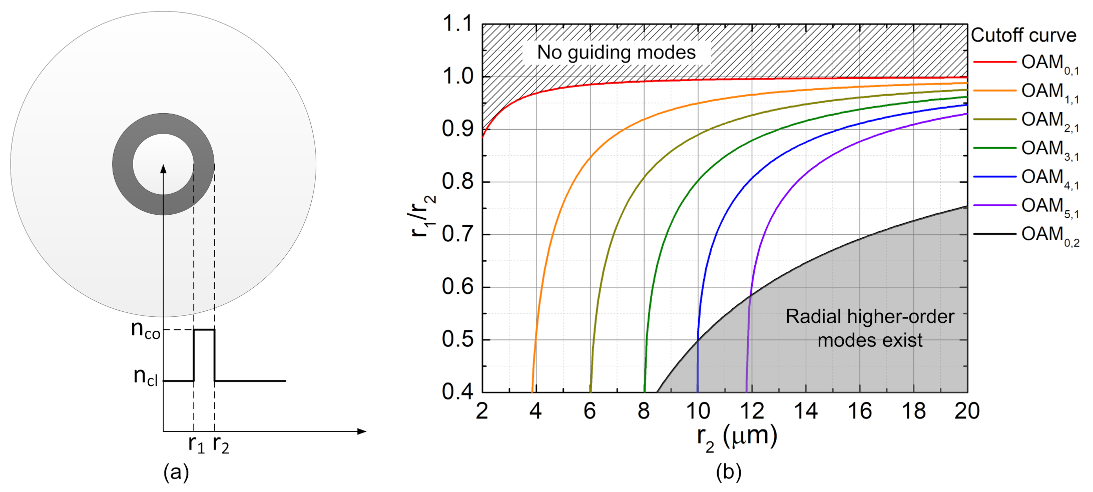
2.2. OAM Modes in Ring-Core Fibers

The azimuthal higher-order vector modes or OAM modes in circularly symmetrical optical fiber have a donut-shaped intensity pattern. One may be inspired to think that the waveguide index profile mimicking the donut shape may provide a more stable environment for the transmission of OAM modes. The pioneering works on the stable transmission of vector modes were done by Ramachandran et al., who adopted a first-order perturbation analysis to provide physical insight into the degeneracy of vector modes. Taking the first-order vector modes as an example, the propagation constant of each mode can be expressed by adding a vector correction to the scalar propagation constant β ˜ , that is [34]
β TE 01 = β ˜ , β TM 01 = β ˜ 2 ( δ 1 + δ 2 ) , β HE 21 = β ˜ + ( δ 2 δ 1 ) ,
where
δ 1 = Δ n max 2 a 2 n co β 0 r E ( r ) E ( r ) r ( Δ n ( r ) / Δ n max ) r d r
δ 2 = Δ n max 2 a 2 n co β 0 E 2 ( r ) ( Δ n ( r ) / Δ n max ) r d r ,
where r is the radial coordinate, E ( r ) is the electric field for the scalar mode, a is the size of the fiber core, Δ n ( r ) is fiber refractive index profile relative to the cladding index, and Δ n max is the highest refractive index difference. The expressions of δ 1 and δ 2 indicate that, when the electric field has a high changing rate and large amplitude in the region of refractive index discontinuities, the polarization orientation of modes will cause a large additional propagation constant. Since a ring core has inner and outer discontinuous boundaries of refractive index, the Δ n eff between the near-degenerate vector modes can be effectively enlarged. Figure 4a shows the index profile of a fabricated novel RCF and the simulated intensity distribution of the first higher-order mode group (HOMG). Although the fiber has a high refractive index core at the center, it does not damage the guidance of the first HOM in the ring core. Most of the mode energy is guided in the ring core, which is the case expected to help with mode stability. The n eff of TE 0 , 1 , HE 2 , 1 , and TM 0 , 1 measured by recording grating resonance wavelength are shown in Figure 4b. We can see that the n eff for each pair of modes is separated well. The minimum Δ n eff between TM 0 , 1 and the other modes is no less than 1.8 × 10 4 ; it is much higher than the value in conventional CCFs, which is of the order of 10 5 . The stability of the first-order vector modes in this RCF was measured. Under the perturbations of multiple twists and bends with bending radius down to 1 cm , the mode purity can remain 99.8 % after transmitting through the 20 m long fiber.
Later, the stable transmission and manipulation of the first-order OAM modes were achieved in RCF [47]. Theoretically, using the same design philosophy, more stable OAM modes can be accommodated into a RCF by increasing the core size and refractive index contrast. However, the radial HOMs may access fiber accompanying the azimuthal HOMs. To eliminate the mode coupling caused by undesired radial HOMs, an optimized design can be applied to RCF to suppress radial HOMs without damaging azimuthal HOMs [48]. Since a radial HOM has a multi-layer ring intensity pattern, narrowing down the ring core thickness can effectively suppress the existence of radial HOMs. Figure 5a shows the refractive index profile of a RCF; the ring core thickness is determined by r 1 and r 2 . The cutoff curves of OAM mode groups are shown in Figure 5b. Actually, the cutoff condition of a mode group OAM l , v consists of cutoff curves of a set of near-degenerate modes OAM ± l , v ± and OAM ± l , v ; however, they are too close to be clearly distinguished when the relative index difference between the core and cladding is small ( ( n co n cl ) / n co < 2 % ). Thus, only one cutoff curve is displayed for each OAM mode group. These cutoff conditions define boundaries of parameter regions where a specific number of modes is supported in the fiber. The curve of OAM 0 , 2 forms a design boundary for eliminating all the radial HOMs. In the region above this cutoff curve (unshaded region), the radial order of all modes is one. In the gray shaded region below the cutoff curve, the modes with v > 1 become guided in the fiber. Therefore, by tuning the values of r 2 and r 1 / r 2 , a fiber can support a targeted number of OAM l , 1 without introducing radial HOMs.
The stable propagation of multiple azimuthal higher-order OAM modes in a RCF was first demonstrated in 2013 [49]. The authors designed and fabricated a RCF with a central air-hole which maximizes the refractive index gradient at the inner boundary of the ring core. This large refractive index gradient coincides with modal field gradient yields large Δ n eff of OAM modes. The best propagation stability was measured on the eighth-order OAM mode, which had ∼20 dB mode purity at the output end of a 1 km long fiber. After that, many research works were done to optimize the design and fabrication of AH-RCFs [35,50,51,52]. An interesting phenomenon found in AH-RCFs was that the OAM longevity increases with mode order [35], which is contrary to the common intuition that fundamental states of systems are the most stable. To test modal stability, circularly polarized OAM modes were generated by a SLM and a quarter-wave plate and then were coupled into a 10 m long AH-RCF. The output OAM modes purities were measured under the condition of arbitrary fiber bending and twisting, as schematically illustrated in Figure 6a. The air-hole radius of the under test AH-RCF is 3 μ m , and the outer radius of the ring core is 8.25 μ m shown in Figure 6b. The central air-hole forces the modes to distribute more intensity at the outer boundary of the ring core, and modes will “feel” more of the large refractive index difference between the ring core and cladding. Hence, the n eff of modes with OAM and SAM aligned (having the same handedness) will be separated from those with OAM and SAM anti-aligned (Figure 6c). Furthermore, the separation level of n eff increases with the OAM order. A Δ n eff around 10 4 is considered reasonable for OAM mode propagation [43]; in this fiber, the OAM modes with | L | = 5 , 6 and 7 can meet the requirement, as indicated in Figure 6d. In addition, the perturbation has weaker effects on modes with the increase of mode order [35]. The perturbation of fiber bends and geometrical deformations can be expanded into Fourier series, where the azimuthal factor of each element can be expressed as f p ( r ) exp ( i p ϕ ) . Since the coupling coefficient is determined by the inner product between the first OAM mode E 1 ( r ) exp ( i L 1 ϕ ) , the perturbation factor and the second OAM mode E 1 ( r ) exp ( i L 2 ϕ ) , mode coupling mainly happens when p = L 1 L 2 . For the near-degenerate OAM modes with | L | , because of the requirement of spin alignment, the perturbation can cause mode coupling when p = 2 | L | . However, the f p ( r ) becomes increasingly negligible for large p. Therefore, the higher-order OMA modes gain better stability.
The inter-mode crosstalks of the AH-RCF were measured on a multitude of fiber lengths [36]. Figure 7a illustrates the crosstalks versus fiber length for the | L | = 5 and | L | = 7 OAM modes. The insets show the modal images at the output end of different fiber lengths. The mode intensities gradually evolve from a donut shape into periodical bright spots in the azimuthal direction with the increase of integrated crosstalk. Longer fiber length leads to heavier crosstalk; the growth rate is 1.5 % per kilometer for the | L | = 7 modes and 15 % per kilometer for the | L | = 5 modes. The | L | = 7 modes maintain better mode purities which have crosstalks lower than 10 dB when the fiber length is up to 5.5 km . The measured results are coincident with the prediction of a tanh ( h z ) (where h is the mode coupling coefficient) dependent crosstalk based on coupled-power theory [53]. Similarly, in Figure 6b, the crosstalks of | L | = 6 modes measured in a 1 km long fiber fit the crosstalk curve with an h value of 4.1 × 10 2 km 1 .
Another novel inverse-parabolic graded-index fiber (IP-GIF) was proposed in 2014 [54]. Similar to the RCFs, the IP-GIF has a refractive index valley at the center of cross section; therefore, the fiber modes can feel large refractive gradient in the fiber. Numerical simulation showed that the specially designed IP-GIF enables a large Δ n eff over 2.1 × 10 4 between the vector modes TE 0 , 1 , HE 1 , 1 and TM 0 , 1 . Then, the authors experimentally demonstrated the stable transmission of OAM ± 1 , 1 ± modes in the 1.1 km long IP-GIF.
The IP-GIFs and RCFs, especially the one assisted by a central air-hole, show good ability to separate the n eff of near-degenerate OAM modes. It greatly enhances the stability of OAM modes which is hardly achieved in conventional CCFs. These designs are beneficial to increase fiber transmission capacity via adding spatial modes without resorting to digital signal processing or adaptive optics.

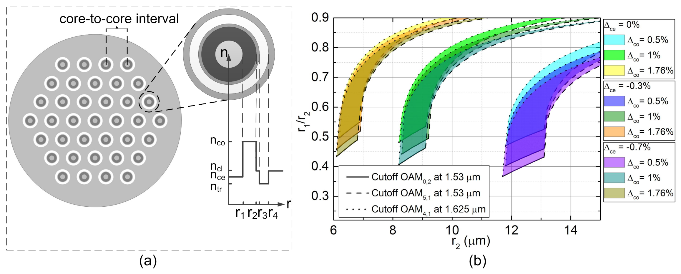
3. Microstructure Optical Fibers Supporting OAM Modes

Photonic crystal fibers (PCFs) which have periodic transverse air-hole arrangements were first proposed and fabricated in 1996 [55]. With the improvement of manufacturing technique, the accuracy of microstructure can reach 10 nm on the scale of 1 μ m [56]. The design of PCFs is more flexible than conventional solid optical fibers, which allows effective control of key modal properties such as dispersion, birefringence, nonlinearity and cutoff conditions. Inspired by the success of PCFs, other kinds of microstructure fibers such as photonic band gap fibers (FBGFs) [57], Kagome fibers [58,59], and negative-curvature fibers [60,61] were proposed to guide optical modes in an air core. These novel guiding mechanisms of microstructure fibers can be adopted to design special OAM fibers.

3.1. Photonic Crystal Fibers Supporting OAM Modes

The common structure of a PCF is to arrange a regular hexagonal lattice of air-holes symmetrically around a central pure silica core. The equivalent refractive index of the cladding is lower than that of the core due to the air-holes. Thus, optical modes can be well confined in the core. When a PCF is periodically twisted in the longitudinal direction, the cladding light will be guided in the helical lattice of air-holes [62]. The spiral path regulated by air-holes (Figure 8a) will transfer a fraction of the axial momentum into angular momentum, causing the formation of cladding orbital angular momentum states. Furthermore, the wavelengths of the cladding OAM modes vary linearly with the twist rate. However, in this fiber, no stable OAM modes can be transmitted in the core region.
Later, a phenomenon of OAM preservation was detected in a helically twisted PCF with a three-bladed Y-shaped core [38]. The schematic pattern and scanning electron micrograph of fiber cross section are shown in Figure 8b,c, respectively. Based on a helicoidal extension of Bloch wave theory, the authors developed a scalar analysis for the modes in the twisted PCF. Figure 8d shows the calculated axial energy flow of a ring mode when the fiber twist rate is 1.26 rad / mm . In the same fiber, the calculated axial Poynting vector of the fundamental mode is shown in Figure 8e. An experiment showed that the chirality of the + 1 order OAM mode was preserved rather than coupled into the 1 order OAM mode, and vice versa in the twisted PCF, which is in agreement with the theoretical prediction.
In addition to the twisted PCFs, a family of RC-PCFs was proposed for OAM mode transmission [37,63,64,65,66]. As shown in Figure 9, the RC-PCFs all adopt circularly symmetric air-hole arrangement, so that the even and odd polarization states of a vector mode will keep well degenerate hence making sure the stability of the combined OAM modes. In [64], three layers of air-holes were used to form the cladding region (Figure 9a). The authors proved that the Δ n eff between the even and odd polarization states are around 10 9 when the number of air elements in each layer is no less than 24. In this case, the fiber structure-caused circular asymmetry is negligible compared with the deformations that arise from external perturbation such as bending and twisting. In the same year, RC-PCFs supporting 14 [37] and 26 [65] OAM modes were designed and analyzed, successively (Figure 9b,c). In these works, identical air-holes were used to construct four circular cladding layers. This design contributes to keeping a similar swelling force in each air-hole, which helps to maintain ideal cross section geometry during the fabrication. The high air-hole filling ratio of the cladding region leads to an equivalent refractive index much lower than that of pure silica; therefore, both inner and outer boundaries of the ring core have very large index gradients. The electric field of modes with a relatively lower-order concentrate and vary rapidly in the vicinity of the inner refractive index step, thus the Δ n eff of near-degenerate modes such as ( HE 2 , 1 , TE 0 , 1 , TM 0 , 1 ) is very large. However, with the increase of mode order, the Δ n eff first reduces, and then rebounds to grow after a certain order. Because the modal fields move to the outer region of the ring core with the increase of mode order, the great index step at the outer core boundary becomes dominant to cause large Δ n eff between near-degenerate modes in the HOMGs.
In 2019, a PCF with cladding consists of a circular layer of air-hole and three hexagonal layers of air-hole were designed and fabricated [66]. Figure 9d shows the designed fiber cross section. The circular arrangement of the first layer air-holes can help to minimize the Δ n eff between the even and odd polarization states of the same vector mode. Furthermore, three outer layers of air-holes contribute to increasing the light confinement in the ring core. The hexagonal arrangement of the outer air-holes makes the fiber easier to be manufactured by the stack-and-draw method. The scanning electron micrograph of the fabricated RC-PCF is shown in Figure 9e. The ring core maintains a good circular symmetry. However, the fabricated fiber has a relatively large transmission loss of 50 dB / km , and only the transmission of the first- and second-order OAM modes was demonstrated in the experiment.

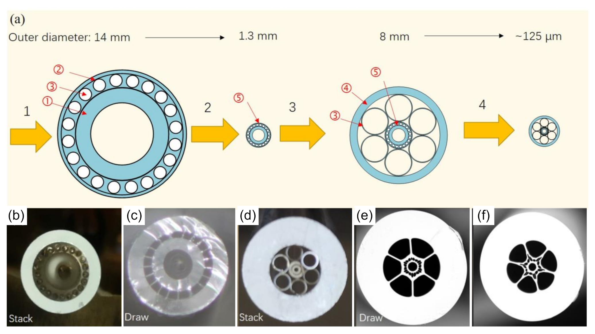
3.2. Negative-Curvature Ring-Core Fibers for OAM Modes Transmission

In 2011, Wang et al. proved that a hypocycloid-shaped core structure can enhance light confinement in Kagome fibers [59]. Furthermore, by simplified the Kagome cladding into a layer of silica tubes, a kind of negative-curvature fiber was proposed to guide light in a quasi-air environment with ultra-wide bandwidth, low scattering loss, and weak nonlinearity [60,61,67,68,69]. These designs provide valuable references to improve the cladding structure of RC-PCFs.
Enlightened by the negative-curvature fibers, our group studied a new kind of negative-curvature ring-core fiber (NC-RCF). The loss comparison between the multi-layered hollow-core fiber and negative-curvature hollow-core fiber is shown in Figure 10a [39]. When the number of air–silica interfaces is the same (four layers), the confinement loss of negative-curvature hollow-core fiber is much lower. Therefore, to increase the number of supported OAM modes with achieving ultra-low loss for the HOMs, an NC-RCF (Figure 10c) was proposed that originate from RC-PCF (Figure 10b). The thickness of the cladding tubes should meet the antiresonant condition for the central wavelength of the transmission band that [69,70,71]
t = λ ( M 0.5 ) 2 n g 2 1 ,
where λ is the free space wavelength, n g is the refractive index of silica glass, and M represents the order of antiresonance ( = 1 , 2 , 3 ) .
Another interesting property of NC-RCF is that the modes formed in the thin membranes of the cladding tubes can couple with certain core modes. Then, the undesired core modes can be effectively filtered out by the coupling caused the large loss. In Figure 10e–h, red regions represent silica and white regions represent air. The simulated confinement losses of the HE 3 , 1 mode in the four designs are shown in Figure 10d. It is easy to understand that the silica cladding and air cladding designs have the highest and lowest confinement loss, respectively. The green and black lines in Figure 10d show the confinement losses of NC-RCF when t = 2.5 μ m and t = 2 μ m , respectively. When t is 2 μ m , the confinement ability of negative curvature tubes is very close to that of air cladding. However, when t increases to 2.5 μ m , antiresonant and inhibited coupling conditions are not satisfied. Hence, a lot of energy was coupled into the tube membrane modes and caused a very high loss, which can be understood by observing the electric field distribution of HE 3 , 1 mode shown on the right side of Figure 10d.
The detailed structure of NC-RCF and the descriptions of the parameters are illustrated by Figure 11a,b. We took r = 7 μ m , ρ = 0.65 , t = 1.2 μ m , and d / Λ = 0.8 as an example to discuss the fiber properties. To prevent the HE- and EH-synthesis OAM modes coupling into LP modes during the propagation, Δ n eff should be larger than 10 4 , which is the minimum modal birefringence of the polarization-maintaining fibers. Figure 11c shows the simulated spectra of Δ n eff between the adjacent vector eigenmodes in an OAM mode group. As the TE 0 , 1 and TM 0 , 1 are filtered out, only HE 2 , 1 mode remains in OAM Mode Group # 1 . Therefore, the case of Group # 1 is excluded in Figure 11c. It can be seen that the requirement of > 1 × 10 4 is met in the wavelength band from 1.4 to 1.8 μ m for OAM Mode Groups # 2 , # 3 , # 4 , # 5 , # 6 , and # 8 . In this fiber, the Δ n eff within a mode group decreases with the order of mode group (except for the Mode Group # 8 ). Such variation trend of Δ n eff is opposite to that in the AH-RCF illustrated in Section 2.2. It is because the equivalent refractive index of cladding of our designed fiber is close to 1, thus the large core/cladding refractive index difference makes the lower-order mode group distribute approaching the inner air–silica boundary, and hence generates a higher Δ n eff between vector eigenmodes in the mode group. This property will be good for the use of lower-order OAM modes. Figure 11d shows the minimum Δ n eff between the adjacent OAM mode groups over the wavelength from 1.2 to 2.0 μ m . The eigenmodes used for calculating the minimum inter-mode-group Δ n eff are described in Figure 11(b2). The values increase with the order of OAM mode group and wavelength. When the wavelength is larger than 1.2 μ m , all the inter-mode-group Δ n eff exceed 1 × 10 3 . Consequently, in theory, the designed NC-RCF can stably support 26 OAM states in the telecommunication wavelength band, including OAM Mode Groups # 1 (two states), # 2 (four states), # 3 (four states), # 4 (four states), # 5 (four states), # 6 (four states), and # 8 (four states).
The fabrication procedure of the NC-RCF is illustrated in Figure 12a. It includes four steps: (1) stack the center preform; (2) draw the center cane; (3) stack the fiber preform; and (4) draw the fiber. In the second and fourth steps, the cane and tubes should be sealed at one end to keep positive air pressure in the hollow holes for maintaining the fiber structure during drawing. Furthermore, in Step 4, a vacuum pump should be used to help reserve the hollow structure during the fiber drawing. Figure 12e,f shows the fibers fabricated under the vacuum level of ∼60 kPa at the temperature around 1880 C and ∼40 kPa at the temperature around 1895 C , respectively. We can see that the intervals between the cladding tubes and the central casing tube are filled in by silica; therefore, the fabricated fibers have much higher confinement loss than that predicted in simulation. The minimum transmission losses of OAM 1 , 1 in Fibers (e) and (f) are 0.3 and 0.095 dB / m , respectively. The higher loss in Fiber (e) is caused by the relatively thicker silica layer surrounding the core, which leads to the leakage of energy from the ring core to the cladding silica through mode coupling.
Finally, we compare the different kinds of fibers supporting OAM mode in Table 1. The recorded number of OAM mode transmissions is 36, achieved by a AH-RCF in 2014. In addition, the maximum transmission length of OAM modes is 13.4 km using a loop of AH-RCF in 2016. Although, theoretically, RC-PCFs and NC-PCFs provide a larger Δ n eff between the near-degenerate modes, which help to enhance the mode stability, no experiment demonstrates the long-distance stable transmission of OAM modes in these two kinds of fibers. The main reason is that RC-PCFs and NC-PCFs may suffer relatively large geometrical deformation during the fabrication. Then, the refractive index fluctuation will cause severe mode coupling. We believe that the performance of RC-PCFs and NC-PCFs will be improved with the progress of the fabrication technique.

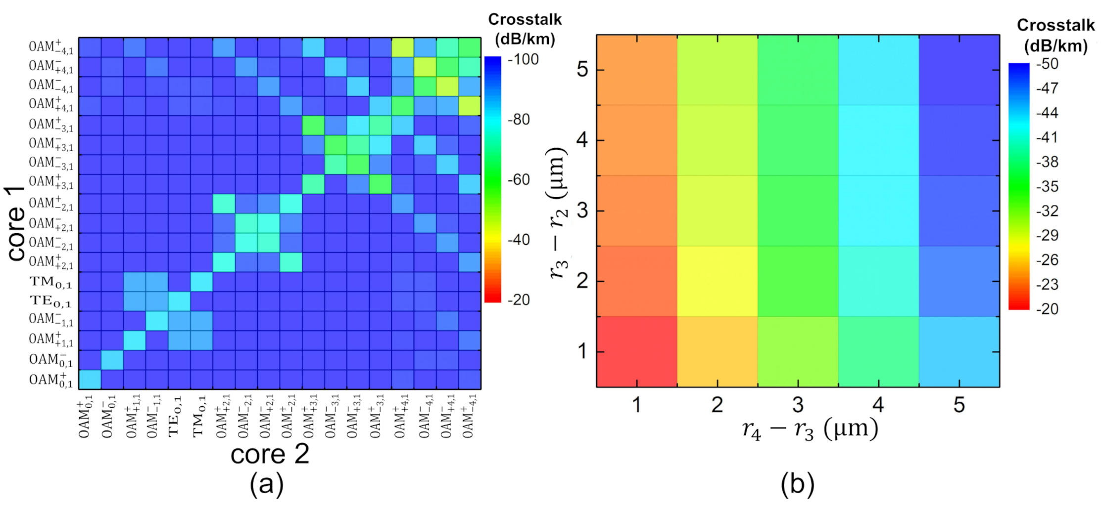
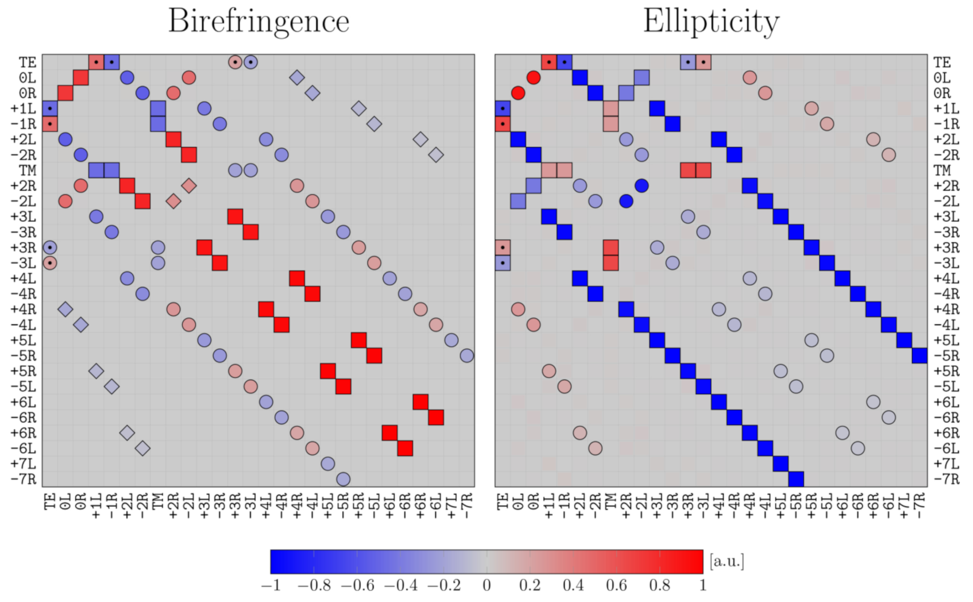
4. Crosstalk Analysis of OAM Modes in Optical Fibers

Multi-core fiber (MCF) is regarded as a good solution for increasing data transmission capacity and saving fiber consumption for the next generation of fiber-optic networks. When the mode coupling between fiber cores is sufficiently small, each core can be regarded as an independent signal channel. Many studies have been done for reducing the inter-core crosstalk, including the studies on heterogeneous and trench-assisted MCFs [72,73,74,75,76]. By optimizing the core structure and arrangement, ultra-low inter-core crosstalk and high core density can be achieved simultaneously [75].
Those experiences in designing MCFs provide good references for the design of MRCFs. Figure 13a shows the refractive index profile of a step-index trench-assisted MRCF. The design region of the size of ring core for supporting a certain number of OAM mode groups can be tuned by changing the central refractive index ( n ce ) and the core refractive index ( n co ). Figure 13b illustrates the design region for supporting mode groups from OAM 0 , 1 to OAM 4 , 1 and cutting off all the radial HOMs in the C+L band (from 1.53 μ m to 1.625 μ m ). The boundaries of each design region are formed by the cutoff curves of OAM 0 , 2 and OAM 5 , 1 at the wavelength of 1.53 μ m and OAM 4 , 1 at the wavelength of 1.625 μ m , respectively. When the relative index difference of the core ( Δ co = ( n co n cl ) / n co ) increases, the available values of the outer radius of ring core ( r 2 ) decreases. The smaller core size is beneficial to the compact design of MRCFs. In addition, the negative relative index difference of the central area ( Δ ce = ( n ce n cl ) / n ce ) can force the n eff of OAM 0 , 2 fall to the cladding refractive index more quickly. As shown in Figure 13b, the cutoff curve of OAM 0 , 2 occurs at a smaller value of r 1 / r 2 when Δ ce decreases, which indicates that the available width of the ring core can be extended. In the experiment, a relatively thicker ring core can help to increase the mode stimulation efficiency at the fiber input end and improve modal stability during transmission.
The inter-core coupling is an essential issue in MRCF. When the core-to-core interval is sufficiently large, the adjacent cores can be regarded as refractive index perturbations of each other. Based on coupled-mode theory, the inter-core mode coupling coefficient of mode m in core i caused by mode n in core j can be calculated by an overlap integral as [33]
c m n ( i ) ( j ) = ω ϵ 0 A ( n ( j ) 2 n cl 2 ) e m ( i ) · e n ( j ) * d A A z ^ · ( e m ( i ) × h m ( i ) * + e m ( i ) * × h m ( i ) ) d A A z ^ · ( e n ( j ) × h n ( j ) * + e n ( j ) * × h n ( j ) ) d A ,
where n ( j ) is the refractive index profile of core j, n cl is the cladding refractive index, and e and h are the electric and magnetic components of modes. However, in the case that the cores are not identical, the conventional mode coupling coefficient are not symmetric. Therefore, when only considering the forward propagation modes, the total power may not be conserved. To satisfy the law of power conservation, redefined mode coupling coefficients C m n ( i ) ( j ) and C n m ( j ) ( i ) were used; their definitions are the average of the usual mode coupling coefficients [77]
C m n ( i ) ( j ) = c m n ( i ) ( j ) + c n m ( j ) ( i ) 2 = C n m ( j ) ( i ) .
Because real optical fiber is not perfect, there is a random phase difference between fiber modes, which is a function of propagation length δ f ( z ) . To consider the effect of the random phase difference, the fiber is divided into finite segments in the longitudinal direction. Furthermore, uniform random phase offsets are applied to all cores in each segment. The overall mode coupling can be obtained by calculating coupled-mode equations in each segment in order.
On the other hand, the inter-core crosstalk can be calculated by coupled-power theory as well [41,77]. Based on the assumption that the random phase fluctuation along the fiber is a stationary random process, it has an autocorrelation function: R ( Δ z ) = δ f ( z + Δ z ) δ f * ( z ) . It has been demonstrated that the calculation based on exponential autocorrelation can obtain crosstalk that agrees well with the experiment results in a single-mode MCF. Furthermore, the power coupling coefficient can be expressed by the Fourier transformation of exponential autocorrelation function as [77]
h m n ( i ) ( j ) ( z ) = ( C m n ( i ) ( j ) ) 2 L c 1 + [ Δ β m n ( i ) ( j ) ( z ) L c ] 2 ,
where Δ β m n ( i ) ( j ) ( z ) represents local propagation constant difference of mode m in core i and mode n in core j and L c is the correlation length of R ( Δ z ) . To take into account the effects of fiber bending and twisting without using numerical solutions, a closed-form average power coupling coefficient was proposed for estimating the inter-core crosstalk in MCFs [78]. It represents the average power coupling coefficient over a twist pitch as
h ¯ m n ( i ) ( j ) = γ 2 π 0 2 π / γ h m n ( i ) ( j ) ( z ) d z ,
where γ is the rate of fiber twisting. By solving power coupling equations, the crosstalk between the two modes can be expressed as
XT m n ( i ) ( j ) = 10 log 10 [ tanh ( h ¯ m n ( i ) ( j ) z ) ] .
The crosstalk values calculated by using the average power coupling coefficient were demonstrated to agree well with experimental results [78]. It provides a fast and accurate method for estimating inter-core crosstalk in bent and twisted MCFs.
Using the average power coupling coefficient, we can analyze the variation trend of inter-core crosstalk in MRCFs. Figure 14a illustrates the inter-core crosstalk between two identical fiber cores. Each fiber core can support up to the fourth-order OAM mode group. We can find that the relatively heavy crosstalk exists between the modes in the same mode group, which is because modes having similar Δ n eff easily meet the phase-matching condition. In addition, the crosstalk increases with the mode order. As the higher-order OAM mode has a larger fraction of energy distribution in the cladding region, it can “feel” more of refractive index perturbation from the adjacent cores. Therefore, the overlapping integration is greater between the higher-order OAM modes. The maximum crosstalk exist between OAM + 4 , 1 + and OAM 4 , 1 + with the value of 47 dB / m . The variation of the maximum inter-core crosstalk versus the size and position of the trench in the 5-mode-group MRCF is shown in Figure 14b. It is shown that increasing the width of the trench can rapidly reduce the crosstalk, and the gap between core and trench also helps to decrease the crosstalk.
In addition, the inter-mode crosstalk between different OAM modes in the same fiber core was analyzed in strongly guiding ring-core fibers recently [79]. The AH-RCF is a representative of strongly guiding fibers. The large air–silica refractive index contrast can effectively separate the n eff of OAM modes in the same mode group, as discussed in Section 2. However, with the increase of refractive index difference between fiber core and neighboring materials, the purity of OAM modes will decrease. Essentially, an OAM mode in optical fiber has two components contributing opposite circularly polarized OAM states of orders l and l + 2 . According to Equation (2), for HE-synthesis OAM modes, the spin-orbital aligned component with the OAM order l is dominant, while the spin-orbital anti-aligned component with the OAM order l + 2 is relatively weaker. However, for EH-synthesis OAM modes, the weight of the compositions is just opposite to that of HE-synthesis OAM modes. With the increase of the mode guiding level in optical fiber, the intensity of the weak modal component will grow, approaching the dominant modal intensity. Therefore, it is necessary to analyze OAM mode crosstalk in a strongly guiding condition.
The inter-mode crosstalk of OAM modes can be calculated by either coupled-mode theory or coupled-power theory. The only difference from the inter-core crosstalk is that the refractive index perturbation does not originate from adjacent cores (represented by n ( j ) in Equation (6)) but is caused by stress birefringence, core ellipticity, diameter fluctuation, core axis deviation, and so on. In [79], the OAM modes crosstalk are calculated under the influence of stress birefringence and core ellipticity. The normalized mode coupling coefficients are shown in Figure 15. Stress birefringence and core ellipticity induce the same coupling pattern among OAM modes, while the intensities are different. In the case of stress birefringence, the dominate-dominate coupling mainly occurs between cross-polarized OAM modes having the same OAM topological charge. When the perturbation is core ellipticity, the dominate-dominate coupling only happens between OAM modes having a OAM topological charge difference of two. Moreover, the two mode coupling coefficients caused by perturbations have opposite signs for higher-order OAM modes in the region close to the main diagonal. However, the ellipticity-caused coupling close to the main diagonal is weaker because it is induced by dominant-weak interaction. The two distributions indicate that the effects of birefringence and ellipticity tend to partially compensate one another.

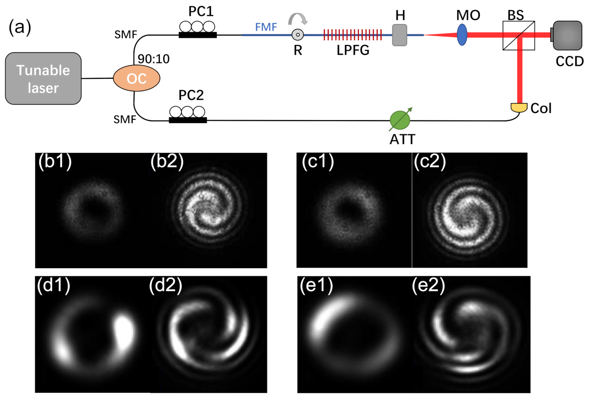
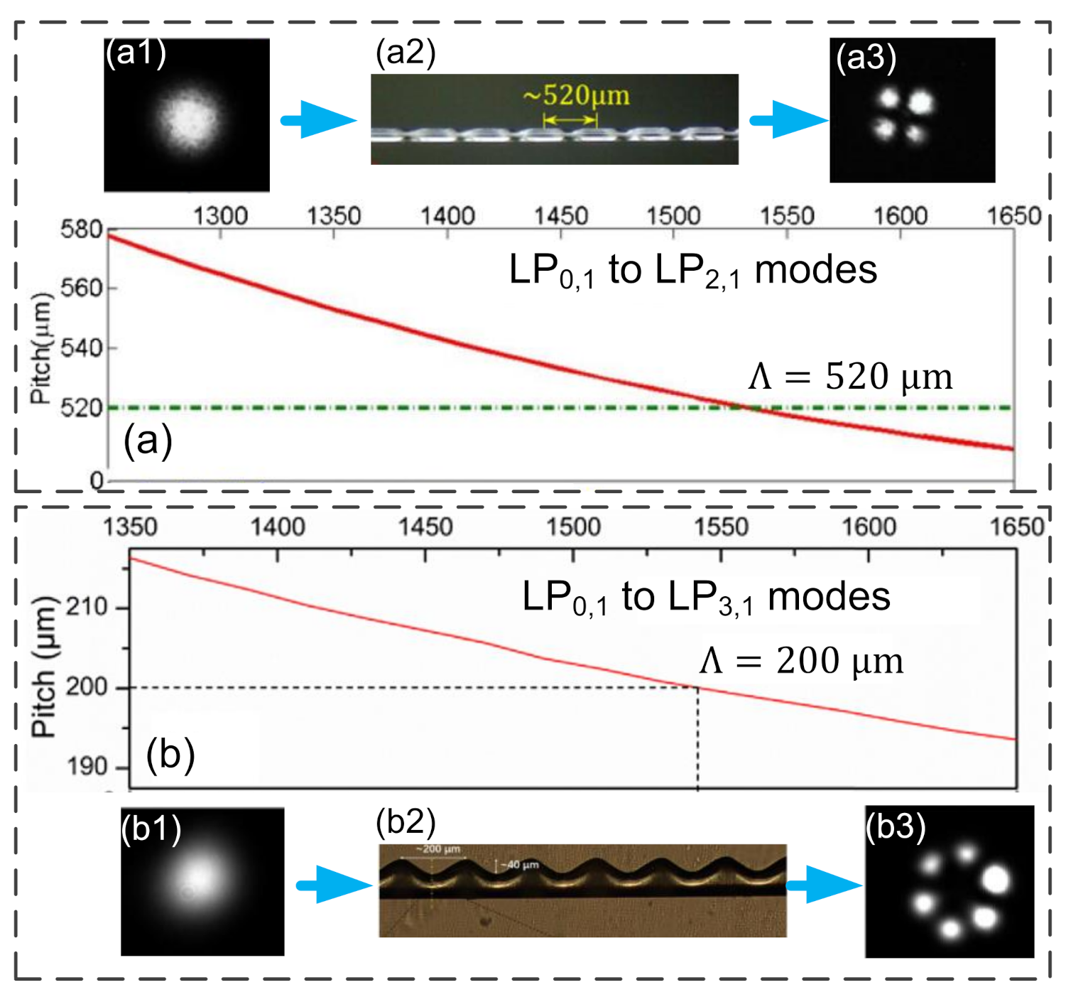
5. All-Fiber OAM Generator

All-fiber OAM mode generators have the advantages of compatibility with fiber systems, low insertion loss, easy integration, and low cost. Therefore, although OAM beams can be efficiently generated by commercial SLMs, all-fiber OAM mode generators still receive increasing attention in recent years.
Using LPFGs is an effective way to convert the fundamental mode to OAM modes in optical fibers. Our group proposed to adopt asymmetric LPFGs to directly generate higher-order OAM modes from the fundamental. We first consider the generation of second-order OAM modes. In a four-mode fiber, the grating pitch ( Λ ) is determined by the phase-matching equation Λ = λ / ( n 0 , 1 n 2 , 1 ) , where n 0 , 1 and n 2 , 1 are the effective refractive index of the LP 0 , 1 and LP 2 , 1 modes, respectively. As shown in Figure 16a, the calculated Λ in the vicinity of λ = 1530 nm is ∼520 μ m . The fabrication of the asymmetric LPFG was using a focused CO 2 laser with high power periodically irradiating a 4-mode fiber from one side [24]. Figure 16(a2) shows the image of asymmetric LPFG; the strong geometrical deformation can cause a large modulation on n eff with the value about 1.1 × 10 2 . In addition, since the deformation is asymmetric, the modulation is not uniform but azimuthal varying. As a result, the power of LP 0 , 1 mode can be effectively coupled into LP 2 , 1 mode. In the same manner, an asymmetric LPFG can be fabricated on a 6-mode fiber to convert LP 0 , 1 to LP 3 , 1 . Since these two modes have a larger Δ n eff , the required Λ becomes smaller. As shown in Figure 16b, the calculated Λ is ∼200 μ m in the vicinity of λ = 1543 nm . To make large geometrical deformations, the six-mode fiber was scanned six times by a CO 2 laser with increasing power step by step [25]. Figure 16(b2) shows the image of asymmetric LPFG with Λ = 200 μ m . The large geometrical deformation breaks the orthogonality between LP 0 , 1 and LP 3 , 1 , which enhances the coupling between these two modes. The fabricated asymmetric LPFGs tested have mode conversion efficiencies of 99.7 % and 99.8 % for LP 2 , 1 and LP 3 , 1 , respectively.
The experimental setups for the generation and detection of OAM modes using the fabricated asymmetric LPFGs are shown in Figure 17a. A tunable laser was used as an optical source. Furthermore, the input light was divided into a generation branch (upper one) and a reference branch (lower one) using a 90:10 optical coupler. The 90 % energy branch was used for the OAM generation. A single-mode fiber (SMF) was coaxially spliced with the under test few-mode fiber (FMF) to stimulate the fundamental mode. Polarization Controller 1 (PC1) was used to adjust the polarization states of the incident fundamental mode to the asymmetric LPFG. It was used to determine the power ratio of the even and odd polarization states of the generated higher-order LP mode. One end of the LPFG was clamped by a fiber holder, while the other end was mounted at the center of a rotator. The relative phase difference between the even and odd polarization states of the target LP mode can be adjusted by twisting the LPFG with the rotator. The generated mode was collimated by a microscope and then transmitted into the charge-coupled device (CCD) camera. The measured mode intensity patterns are shown in Figure 17(b1–e1). To verify the number of the OAM topological charge, a reference Gaussian beam in the lower branch was adjusted into the same power level as the generated OAM beam and was combined with the OAM beam using a beam splitter (BS). Then, we can see the OAM order according to the interference patterns. Figure 17(b2,c2) indicates that the generated modes were OAM + 2 , 1 and OAM 2 , 1 . In the same way, the interference patterns in Figure 17(d2,e2) show that the generated modes were OAM + 3 , 1 and OAM 3 , 1 . These works demonstrated a feasible way to produce low-cost compact all-fiber OAM generators.
In addition, many valuable works on all-fiber OAM generators were reported by other groups. In 2015, Li et al. first proposed a controllable all-fiber OAM mode converter [23]. As shown in Figure 18a, at the input end, a SMF is spliced coaxially with a two-mode fiber to efficiently stimulate the fundamental mode in the two-mode fiber. Then, a mechanical long-period grating is applied on the two-mode fiber to convert the fundamental mode to the LP 1 , 1 mode. Then, a rotator is used to adjust the intensity orientation of the LP 1 , 1 mode to the pressure applying slabs. When the orientation angle is 45 , the energy of the vertical and transverse polarization components are the same. By applying pressure to modify the circular core into an elliptical core, a Δ n eff is generated between the vertical and transverse polarization components.
Then, the first-order OAM mode can be generated when the two components have a ± π / 2 phase difference at the output end. Moreover, the grating pitch applied to the fiber can be tuned by placing the fiber at different angles to the mechanical long-period grating. It achieves a scalable scheme to generate OAM modes at different wavelengths.
However, the mechanical long-period grating is relatively bulky, and a more compact OAM generator by using an all-fiber mode selective coupler was proposed in 2018 [22]. In Figure 18b, the coupler is fabricated by tapering a SMF and a graded-index FMF together with a proper diameter ratio. The FMF used here is in the strong guiding condition, which can well separate the n eff of HE 2 , 1 from those of TE 0 , 1 and TM 0 , 1 . Hence, the coupling efficiency into HE 2 , 1 is increased. In the experiment, a polarization controller was used to adjust the purity of the generated first-order OAM mode. Finally, a purity of ∼95% was obtained.
The above-mentioned all-fiber OAM generators are sensitive to the polarization states of fiber modes, which may have instability in applications. In 2019, a polarization-independent OAM generator based on a helical fiber grating was proposed [26]. As illustrated in Figure 18c, the helical fiber grating was produced by twisting a FMF during hydrogen-oxygen flame heating. Through carefully setting the rotation speed of the rotator and the moving speeds of the two translation stages, the pitch of the helical grating can be well kept. In their works, the resonant wavelengths of the right-handed helical grating and left-handed helical grating are 1550.9 and 1554.5 nm , respectively. The two samples were tested in experiments. The results show that the first-order OAM modes can be generated with a mode purity of around 93 % . Furthermore, the polarization state of the output OAM modes is consistent with the polarization state of the input light. Since no coupling was observed between the + 1 -order and 1 -order OAM modes, it is indicated that the OAM chirality was determined only by the twisting direction of the helical fiber grating.
Recently, a further work on helical fiber grating based all-fiber OAM generator was reported. By taking advantage of the second and third diffraction orders of a helical fiber grating, the second- and third-order OAM modes can be simultaneously generated in a single fiber [27]. Figure 18(d1,d2) shows the n eff of modes and grating resonant conditions in a four-mode fiber. In Figure 18(d1), we can see that the fiber can only support the LP 3 , 1 mode when the wavelength is smaller than 1440 nm , while the other three LP modes can be well guided in the fiber in the wavelength band from 1400 to 1700 nm . The grating resonant pitches and Δ n eff of modes are shown in Figure 18(d2). The resonant coupling from LP 0 , 1 to LP 2 , 1 occurs at the wavelength of 1580 nm , and that from LP 0 , 1 to the cladding mode (noted as LP 3 , 1 to be consistent with the notation in Figure 18(d2) occurs at the wavelength of 1555 nm . Therefore, the fundamental fiber mode can be converted directly into OAM 2 , 1 and OAM 3 , 1 at the two specific wavelengths, respectively. From the experiment, the maximum purities for the OAM 2 , 1 and OAM 3 , 1 were 95 % and 98 % . In addition to OAM modes generators, chiral fiber gratings can also be applied as torsion sensors, band-rejection filters, wave plates and linear- and circular-light polarizers. The mode-coupling theories, fabrication techniques and applications of helical fiber gratings can be found in a detailed and comprehensive review contributed by Zhao Hua and Li Hongpu [80].

6. Conclusions and Prospects

The stability of OAM mode transmission in optical fibers has obtained great improvements in the last decade. Using an AH-RCF, the best record for stable OAM mode transmission reached 13.4 km [36]. In addition, many simulation works have been done on microstructure fibers for OAM mode transmission. Some of these designs were manufactured and tested. Although the produced microstructure fibers have geometrical deformations from the ideal design, they performed the transmission ability for OAM modes in experiments. Therefore, these exploratory works provide flexible designs for OAM fiber and expand the application of OAM modes in the aspects of enhancing data transmission capacity in fiber links, OAM-based fiber imaging, and vortex-mode fiber lasers. In addition, the studies on the all-fiber OAM generator provide alternative choices to commercially available free-space devices. Those all-fiber devices are suitable for applications requiring low insertion loss, good alignment stability, and high integration.
However, the stability of OAM modes in optical fibers needs to be further improved for long-haul, high-capacity data transmission. Although the first-order perturbation theory reveals that increasing the refractive index contrast between core and cladding can split the n eff between the near-degenerate OAM modes, the variation trends of Δ n eff among near-degenerate OAM modes with different OAM orders are not consistent. Therefore, there is no mature design scheme for obtaining the optimized combination of guiding mode number and mode stability level. On the other hand, improving the fiber fabrication technique is necessary for improving mode stability. How to keep the hollow structures of AH-RCF and microstructure RCF during fiber fabrication still need to be studied.
For fiber-optic communications, in recent years, a scheme of SDM assisted by low-complexity modular multi-input multi-output (MIMO) equalization was proposed for recovering the signal from the crosstalk among the near-degenerate OAM modes [81]. According to the maximum degeneracy of a fiber mode group, a 4 × 4 MIMO is sufficient for signal processing. In this scheme, the crosstalk between the near-degenerate OAM modes is no longer the crucial issue; instead, the crosstalk between OAM mode groups becomes the main barrier for increasing the signal quality. Therefore, the fibers suitable for this scheme should achieve low crosstalk between OAM mode groups while having low differential group delay between the near-degenerate OAM modes. The fibers will need no ultra-high refractive index contrast structures such as the air-hole to separate the n eff of near-degenerate OAM modes. Thus, these fibers may have higher fabrication reliability and can be expanded to a multi-core design.
Finally, we should note that active OAM fiber-optic devices such as OAM fiber amplifiers are also important for building long-haul OAM mode fiber links. Although there are many challenges related to mode stability, generation efficiency, multiplexing, de-multiplexing, and amplification in the field of OAM, it provides new frontiers for optical communication systems and microscopy techniques.

Author Contributions

Writing–original draft preparation, Z.W.; writing–review and editing, J.T. and C.Y.; investigation and resources, S.G. and Z.L.; supervision, C.L. All authors have read and agreed to the published version of the manuscript.

Funding

This work was supported by National Key R&D Program of China 2019YFA0706300 from Ministry of Science and Technology, China; National Natural Science Foundation of China (NSFC) (Grant No. U1701661 and U2001601); and Guangzhou basic and applied basic research Foundation (Grant No. 202002030327).

Conflicts of Interest

The authors declare no conflict of interest.

References

  1. Beth, R.A. Mechanical detection and measurement of the angular momentum of light. Phys. Rev. 1936, 50, 115–125. [Google Scholar] [CrossRef]
  2. Yao, A.M.; Padgett, M.J. Orbital angular momentum: Origins, behavior and applications. Adv. Opt. Photonics 2011, 3, 161–204. [Google Scholar] [CrossRef] [Green Version]
  3. Allen, L.; Beijersbergen, M.W.; Spreeuw, R.J.C.; Woerdman, J.P. Orbital angular momentum of light and the transformation of Laguerre-Gaussian laser modes. Phys. Rev. A 1992, 45, 8185–8189. [Google Scholar] [CrossRef] [PubMed]
  4. Franke-Arnold, S.; Allen, L.; Padgett, M. Advances in optical angular momentum. Laser Photonics Rev. 2008, 2, 299–313. [Google Scholar] [CrossRef]
  5. Kuga, T.; Torii, Y.; Shiokawa, N.; Hirano, T.; Shimizu, Y.; Sasada, H. Novel optical trap of atoms with a doughnut beam. Phys. Rev. Lett. 1997, 78, 4713–4716. [Google Scholar] [CrossRef]
  6. Paterson, L.; MacDonald, M.P.; Arlt, J.; Sibbett, W.; Bryant, P.E.; Dholakia, K. Controlled rotation of optically trapped microscopic particles. Science 2001, 292, 912–914. [Google Scholar] [CrossRef]
  7. Garcés-Chávez, V.; McGloin, D.; Padgett, M.J.; Dultz, W.; Schmitzer, H.; Dholakia, K. Observation of the transfer of the local angular momentum density of a multiringed light beam to an optically trapped particle. Phys. Rev. Lett. 2003, 91, 093602. [Google Scholar] [CrossRef]
  8. Mair, A.; Vasiri, A.; Weihs, G.; Zeilinger, A. Entanglement of the orbital angular momentum states of photons. Nature 2001, 412, 313–316. [Google Scholar] [CrossRef] [PubMed] [Green Version]
  9. Mirhosseini, M.; Maga na-Loaiza, O.S.; O’Sullivan, M.N.; Rodenburg, B.; Malik, M.; Lavery, M.P.J.; Padgett, M.J.; Gauthier, D.J.; Boyd, R.W. High-dimensional quantum cryptography with twisted light. New J. Phys. 2015, 17, 033033. [Google Scholar] [CrossRef]
  10. Jesacher, A.; Fürhapter, S.; Bernet, S.; Ritsch-Marte, M. Shadow effects in spiral phase contrast microscopy. Phys. Rev. Lett. 2005, 94, 233902. [Google Scholar] [CrossRef]
  11. Fürhapter, S.; Jesacher, A.; Bernet, S.; Ritsch-Marte, M. Spiral interferometry. Opt. Lett. 2005, 30, 1953–1955. [Google Scholar] [CrossRef]
  12. Gibson, G.; Courtial, M.; Padgett, J.; Vasnetsov, M.; Pas’ko, V.; Barnett, S.M.; Franke-Arnold, S. Free-space information transfer using light beams carrying orbital angular momentum. Opt. Express 2004, 12, 5448–5456. [Google Scholar] [CrossRef] [PubMed] [Green Version]
  13. Wang, J.; Yang, J.Y.; Fazal, I.M.; Ahmed, N.; Yan, Y.; Huang, H.; Ren, Y.; Yue, Y.; Dolinar, S.; Tur, M.; et al. Terabit free-space data transmission employing orbital angular momentum multiplexing. Nat. Photonics 2012, 6, 488–496. [Google Scholar] [CrossRef]
  14. Bozinovic, N.; Yue, Y.; Ren, Y.; Tur, M.; Kristensen, P.; Huang, H.; Willner, A.E.; Ramachandran, S. Terabit-scale orbital angular momentum mode division multiplexing in fibers. Science 2013, 340, 1545–1548. [Google Scholar] [CrossRef] [PubMed] [Green Version]
  15. Willner, A.E.; Huang, H.; Yan, Y.; Ren, Y.; Ahmed, N.; Xie, G.; Bao, C.; Li, L.; Cao, Y.; Wang, J.; et al. Optical communications using orbital angular momentum beams. Adv. Opt. Photonics 2015, 7, 66–106. [Google Scholar] [CrossRef] [Green Version]
  16. Richardson, D.J.; Fini, J.M.; Nelson, L.E. Space-division multiplexing in optical fibers. Nat. Photonics 2013, 7, 354–362. [Google Scholar] [CrossRef] [Green Version]
  17. Sueda, K.; Miyaji, G.; Miyanaga, N.; Nakatsuka, M. Laguerre-Gaussian beam generated with a multilevel spiral phase plate for high intensity laser pulses. Opt. Express 2004, 12, 3548–3553. [Google Scholar] [CrossRef]
  18. Ruffato, G.; Massari, M.; Parisi, G.; Romanato, F. Test of mode-division multiplexing and demultiplexing in free-space with diffractive transformation optics. Opt. Express 2017, 25, 7859–7868. [Google Scholar] [CrossRef] [PubMed] [Green Version]
  19. Li, W.; Morgan, K.S.; Li, Y.; Miller, J.K.; White, G.; Watkins, R.J.; Johnson, E.G. Rapidly tunable orbital angular momentum (OAM) system for higher order Bessel beams integrated in time (HOBBIT). Opt. Express 2019, 27, 3920–3934. [Google Scholar] [CrossRef] [PubMed]
  20. Cai, X.; Wang, J.; Strain, M.J.; Johnson-Morris, B.; Zhu, J.; Sorel, M.; O’Brien, J.L.; Thompson, M.G.; Yu, S. Integrated compact optical vortex beam emitters. Science 2012, 338, 363–365. [Google Scholar] [CrossRef]
  21. Pidishety, S.; Pachava, S.; Gregg, P.; Ramachandran, S.; Brambilla, G.; Srinivasan, B. Orbital angular momentum beam excitation using an all-fiber weakly fused mode selective coupler. Opt. Lett. 2017, 42, 4347–4350. [Google Scholar] [CrossRef]
  22. Heng, X.; Gan, J.; Zhang, Z.; Li, J.; Li, M.; Zhao, H.; Qian, Q.; Xu, S.; Yang, Z. All-fiber stable orbital angular momentum beam generation and propagation. Opt. Express 2018, 26, 17429–17436. [Google Scholar] [CrossRef]
  23. Li, S.; Mo, Q.; Hu, X.; Du, C.; Wang, J. Controllable all-fiber orbital angular momentum mode converter. Opt. Lett. 2015, 40, 4376–4379. [Google Scholar] [CrossRef] [PubMed]
  24. Wu, H.; Gao, S.; Huang, B.; Feng, Y.; Huang, X.; Liu, W.; Li, Z. All-fiber second-order optical vortex generation based on strong modulated long-period grating in a four-mode fiber. Opt. Lett. 2017, 42, 5210–5213. [Google Scholar] [CrossRef] [PubMed]
  25. He, X.; Tu, J.; Wu, X.; Gao, S.; Shen, L.; Hao, C.; Feng, Y.; Liu, W.; Li, Z. All-fiber third-order orbital angular momentum mode generation employing an asymmetric long-period fiber grating. Opt. Lett. 2020, 45, 3621–3624. [Google Scholar] [CrossRef] [PubMed]
  26. Zhang, Y.; Bai, Z.; Fu, G.; Liu, S.; Tang, J.; Yu, J.; Liao, C.; Wang, Y.; He, J.; Wang, Y. Polarization-independent orbital angular momentum generator based on a chiral fiber grating. Opt. Lett. 2019, 44, 61–64. [Google Scholar] [CrossRef] [PubMed]
  27. Detani, T.; Zhao, H.; Wang, P.; Suzuki, T.; Li, H. Simultaneous generation of the second- and third-order OAM modes by using a high-order helical long-period fiber grating. Opt. Lett. 2021, 46, 949–952. [Google Scholar] [CrossRef]
  28. Zhang, N.; Yuan, C.; Burge, R.E. Extending the detection range of optical vortices by Dammann vortex gratings. Opt. Lett. 2010, 35, 3495–3497. [Google Scholar] [CrossRef]
  29. Lei, T.; Zhang, M.; Li, Y.; Jia, P.; Liu, G.N.; Xu, X.; Li, Z.; Min, C.; Lin, J.; Yu, C.; et al. Massive individual orbital angular momentum channels for multiplexing enabled by Dammann gratings. Light Sci. Appl. 2015, 4, e257. [Google Scholar] [CrossRef]
  30. Fontaine, N.K.; Ryf, R.; Chen, H.; Neilson, D.T.; Kim, K.; Carpenter, J. Laguerre-Gaussian mode sorter. Nat. Commun. 2019, 10, 1865. [Google Scholar]
  31. Lin, Z.; Wen, Y.; Chen, Y.; Yu, S. Transmissive Multi-plane Light Conversion for Demultiplexing Orbital Angular Momentum Modes. In Proceedings of the CLEO, SF1J5, Washington, DC, USA, 10–15 May 2020. [Google Scholar]
  32. Ren, Y.; Huang, H.; Xie, G.; Ahmed, N.; Yan, Y.; Erkmen, B.I.; Chandrasekaran, N.; Lavery, M.P.J.; Steinhoff, N.K.; Tur, M.; et al. Atmospheric turbulence effects on the performance of a free space optical link employing orbital angular momentum multiplexing. Opt. Lett. 2013, 38, 4062–4065. [Google Scholar] [CrossRef] [PubMed]
  33. Snyder, A.W. Coupled-mode theory for optical fibers. J. Opt. Soc. Am. A 1972, 62, 1267–1277. [Google Scholar] [CrossRef]
  34. Ramachandran, S.; Kristensen, P.; Yan, M.F. Generation and propagation of radially polarized beams in optical fibers. Opt. Lett. 2009, 34, 2525–2527. [Google Scholar] [CrossRef] [Green Version]
  35. Gregg, P.; Kristensen, P.; Ramachandran, S. Conservation of orbital angular momentum in air-core optical fibers. Optica 2015, 2, 267–270. [Google Scholar] [CrossRef] [Green Version]
  36. Gregg, P.; Kristensen, P.; Ramachandran, S. 13.4 km OAM state propagation by recirculation fiber loop. Opt. Express 2016, 24, 18938–18947. [Google Scholar] [CrossRef]
  37. Zhang, H.; Zhang, W.; Xi, L.; Tang, X.; Zhang, X.; Zhang, X. A new type circular photonic crystal fiber for orbital angular momentum mode transmission. IEEE Photonics Technol. Lett. 2016, 28, 1426–1429. [Google Scholar] [CrossRef]
  38. Xi, X.M.; Wong, G.K.L.; Frosz, M.H.; Babic, F.; Ahmed, G.; Jiang, X.; Euser, T.G.; Russell, P.S.J. Orbital-angular-momentum-preserving helical Bloch modes in twisted photonic crystal fiber. Optica 2014, 1, 165–169. [Google Scholar] [CrossRef]
  39. Tu, J.; Liu, Z.; Gao, S.; Wang, Z.; Zhang, J.; Zhang, B.; Li, J.; Liu, W.; Tam, H.; Li, Z.; et al. Ring-core fiber with negative curvature structure supporting orbital angular momentum modes. Opt. Express 2019, 27, 20358–20372. [Google Scholar] [CrossRef]
  40. Tu, J.; Gao, S.; Wang, Z.; Liu, Z.; Li, W.; Du, C.; Liu, W.; Li, Z.; Yu, C.; Tam, H.; et al. Bend-insensitive grapefruit-type holey ring-core fiber for weakly-coupled OAM mode division multiplexing transmission. IEEE J. Light. Technol. 2020, 38, 4497–4503. [Google Scholar] [CrossRef]
  41. Marcuse, D. Derivation of coupled power equations. Bell Syst. Tech. J. 1972, 51, 229–237. [Google Scholar] [CrossRef]
  42. Snyder, A.W.; Love, J.D. Optical Waveguide Theory, 1st ed.; Chapman and Hall: New York, NY, USA, 1983; pp. 248–254. [Google Scholar]
  43. Ramachandran, S.; Kristensen, P. Optical vortices in fiber. Nanophotonics 2013, 2, 455–474. [Google Scholar] [CrossRef]
  44. Zhang, Z.; Gan, J.; Heng, X.; Wu, Y.; Li, Q.; Qian, L.; Chen, D.; Yang, Z. Optical fiber design with orbital angular momentum light purity higher than 99.9%. Opt. Express 2015, 23, 29331–29341. [Google Scholar] [CrossRef]
  45. Chen, S.; Wang, J. Theoretical analyses on orbital angular momentum modes in conventional graded-index multimode fibre. Sci. Rep. 2017, 7, 3990. [Google Scholar] [CrossRef] [PubMed] [Green Version]
  46. Zhou, W.; Cao, H.; Wang, L.; Wang, J. All-Fiber Orbital Angular Momentum (OAM) Functional Devices for Mode-Division (De)Multiplexing in Conventional Graded-Index Multimode Fiber. In Proceedings of the 2019 Optical Fiber Communications Conference and Exhibition (OFC), Th3D.5, San Diego, CA, USA, 3–7 March 2019. [Google Scholar]
  47. Bozinovic, N.; Golowich, S.; Kristensen, P.; Ramachandran, S. Control of orbital angular momentum of light with optical fibers. Opt. Lett. 2012, 37, 2451–2453. [Google Scholar] [CrossRef] [PubMed]
  48. Brunet, C.; Ung, B.; Bélanger, P.; Messaddeq, Y.; LaRochelle, S.; Rusch, L.A. Vector mode analysis of ring-core fibers: Design tools for spatial division multiplexing. IEEE J. Light. Technol. 2014, 32, 4046–4057. [Google Scholar] [CrossRef] [Green Version]
  49. Gregg, P.; Kristensen, P.; Golowich, S.E.; Olsen, J.Ø.; Steinvurzel, P.; Ramachandran, S. Stable transmission of 12 OAM states in air-core fiber. In Proceedings of the CLEO, CTu2K.2, San Jose, CA, USA, 9–14 June 2013. [Google Scholar]
  50. Brunet, C.; Vaity, P.; Messaddeq, Y.; LaRochelle, S.; Rusch, L.A. Design, fabrication and validation of an OAM fiber supporting 36 states. Opt. Express 2014, 22, 26117–26127. [Google Scholar] [CrossRef]
  51. Ramachandran, S.; Gregg, P.; Kristensen, P.; Golowich, S.E. On the scalability of ring fiber designs for OAM multiplexing. Opt. Express 2015, 23, 3721–3730. [Google Scholar] [CrossRef]
  52. Brunet, C.; Ung, B.; Wang, L.; Messaddeq, Y.; LaRochelle, S.; Rusch, A.L. Design of a family of ring-core fibers for OAM transmission studies. Opt. Express 2015, 23, 10553–10563. [Google Scholar] [CrossRef]
  53. Kawakami, S.; Ikeda, M. Transmission characteristics of a two-mode optical waveguide. IEEE J. Quantum Electron. 1978, QE-14, 608–614. [Google Scholar] [CrossRef]
  54. Ung, B.; Vaity, P.; Wang, L.; Messaddeq, Y.; Rusch, A.L.; LaRochelle, S. Few-mode fiber with inverse-parabolic graded-index profile for transmission of OAM-carrying modes. Opt. Express 2014, 22, 18044–18055. [Google Scholar] [CrossRef]
  55. Knight, J.C.; Birks, T.A.; Russell, P.S.J.; Atkin, D.M. All-silica single-mode optical fiber with photonic crystal cladding. Opt. Lett. 1996, 21, 1547–1549. [Google Scholar] [CrossRef]
  56. Russell, P.S.J. Photonic-Crystal fibers. IEEE J. Light. Technol. 2006, 24, 4729–4749. [Google Scholar] [CrossRef]
  57. Cregan, R.F.; Mangan, B.J.; Knight, J.C.; Birks, T.A.; Russell, P.S.J.; Roberts, P.J.; Allan, D.C. Single-mode photonic band gap guidance of light in air. Science 1999, 285, 1537–1539. [Google Scholar] [CrossRef] [PubMed] [Green Version]
  58. Couny, F.; Benabid, F.; Light, P.S. Large-pitch kagome-structured hollow-core photonic crystal fiber. Opt. Lett. 2006, 31, 3574–3576. [Google Scholar] [CrossRef]
  59. Wang, Y.Y.; Wheeler, N.V.; Couny, F.; Roberts, P.J.; Benabid, F. Low loss broadband transmission in hypocycloid-core Kagome hollow-core photonic crystal fiber. Opt. Lett. 2011, 36, 669–671. [Google Scholar] [CrossRef] [PubMed]
  60. Gao, S.F.; Wang, Y.Y.; Ding, W.; Jiang, D.L.; Gu, S.; Zhang, X.; Wang, P. Hollow-core conjoined-tube negative-curvature fiber with ultralow loss. Nat. Commun. 2018, 9, 1–6. [Google Scholar] [CrossRef] [PubMed] [Green Version]
  61. Jasion, G.T.; Bradley, T.D.; Harrington, K.; Sakr, H.; Chen, Y.; Fokoua, E.N.; Davidson, I.A.; Taranta, A.; Hayes, J.R.; Richardon, D.J.; et al. Hollow core NANF with 0.28 dB/km attenuation in the C and L bands. In Proceedings of the Optical Fiber Communication Conference, Th4B-4, San Diego, CA, USA, 8–12 March 2020. [Google Scholar]
  62. Wong, G.K.L.; Kang, M.S.; Lee, H.W.; Biancalana, F.; Conti, C.; Weiss, T.; Russell, P.S.J. Excitation of orbital angular momentum resonances in helically twisted photonic crystal fiber. Science 2012, 337, 446–449. [Google Scholar] [CrossRef]
  63. Chen, C.; Zhou, G.; Zhou, G.; Xu, M.; Hou, Z.; Xia, C.; Yuan, J. A multi-orbital-angular-momentum multi-ring micro-structured fiber with ultra-high-density and low-level crosstalk. Opt. Commun. 2016, 368, 27–33. [Google Scholar] [CrossRef]
  64. Zhou, G.; Zhou, G.; Chen, C.; Xu, M.; Xia, C.; Hou, Z. Design and analysis of a microstructure ring fiber for orbital angular momentum transmission. IEEE Photonics J. 2016, 8, 7802512. [Google Scholar] [CrossRef]
  65. Tian, W.; Zhang, H.; Zhang, X.; Xi, L.; Zhang, W.; Tang, X. A circular photonic crystal fiber supporting 26 OAM modes. Opt. Fiber Technol. 2016, 30, 184–189. [Google Scholar] [CrossRef]
  66. Tandjè, A.; Yammine, J.; Dossou, M.; Bouwmans, G.; Baudelle, K.; Vianou, A.; Andresen, E.R.; Bigot, L. Ring-core photonic crystal fiber for propagation of OAM modes. Opt. Lett. 2019, 44, 1611–1614. [Google Scholar] [CrossRef]
  67. Pryamikov, A.D.; Biriukov, A.S.; Kosolapov, A.F.; Plotnichenko, V.G.; Semjonov, S.L.; Dianov, E.M. Demonstration of a waveguide regime for a silica hollow-core microstructured optical fiber with a negative curvature of the core boundary in the spectral region >3.5 μm. Opt. Express 2011, 19, 1441–1448. [Google Scholar] [CrossRef] [PubMed]
  68. Kolyadin, A.N.; Kosolapov, A.F.; Pryamikov, A.D.; Biriukov, A.S.; Plotnichenko, V.G.; Dianov, E.M. Light transmission in negative curvature hollow core fiber in extremely high material loss region. Opt. Express 2013, 21, 9514–9519. [Google Scholar] [CrossRef] [PubMed]
  69. Poletti, F. Nested antiresonant nodeless hollow core fiber. Opt. Express 2014, 22, 23807–23828. [Google Scholar] [CrossRef]
  70. Litchinitser, N.M.; Abeeluck, A.K.; Headley, C.; Eggleton, B.J. Antiresonant reflecting photonic crystal optical waveguides. Opt. Lett. 2002, 27, 1592–1594. [Google Scholar] [CrossRef] [PubMed]
  71. Wang, Z.; Tu, J.; Liu, Z.; Yu, C.; Lu, C. Design of weakly coupled two-mode hollow-core antiresonant fiber with low loss. IEEE J. Light. Technol. 2020, 38, 864–874. [Google Scholar] [CrossRef]
  72. Koshiba, M.; Saitoh, K.; Kokubun, Y. Heterogeneous multi-core fibers: Proposal and design principle. IEICE Electron. Express 2009, 6, 98–103. [Google Scholar] [CrossRef] [Green Version]
  73. Takenaga, K.; Arakawa, Y.; Tanigawa, S.; Guan, N.; Matsuo, S.; Saitoh, K.; Koshiba, M. Reduction of crosstalk by trench-assisted multi-core fiber. In Proceedings of the Optical Fiber Communication Conference, OWJ4, Los Angeles, CA, USA, 6–10 March 2011. [Google Scholar]
  74. Tu, J.; Saitoh, K.; Koshiba, M.; Takenaga, K.; Matsuo, S. Design and analysis of large-effective-area heterogeneous trench-assisted multi-core fiber. Opt. Express 2012, 20, 15157–15170. [Google Scholar] [CrossRef]
  75. Tu, J.; Saitoh, K.; Koshiba, M.; Takenaga, K.; Matsuo, S. Optimized design method for bend-insensitive heterogeneous trench-assisted multi-core fiber with ultra-low crosstalk and high core density. IEEE J. Light. Technol. 2013, 31, 2590–2598. [Google Scholar]
  76. Tu, J.; Long, K.; Saitoh, K. An efficient core selection method for heterogeneous trench-assisted multi-core fiber. IEEE Photonics Technol. Lett. 2016, 28, 810–813. [Google Scholar] [CrossRef]
  77. Koshiba, M.; Saitoh, K.; Takenaga, K.; Matsuo, S. Multi-core fiber design and analysis: Coupled-mode theory and coupled-power theory. Opt. Express 2011, 19, B102–B111. [Google Scholar] [CrossRef] [PubMed] [Green Version]
  78. Koshiba, M.; Saitoh, K.; Takenaga, K.; Matsuo, S. Analytical expression of average power-coupling coefficient for estimating intercore crosstalk in multicore fibers. IEEE Photonics J. 2012, 4, 1987–1995. [Google Scholar] [CrossRef] [Green Version]
  79. Guerra, G.; Lonardi, M.; Galtarossa, A.; Rusch, L.A.; Bononi, A.; Palmieri, L. Analysis of modal coupling due to birefringence and ellipticity in strongly guiding ring-core OAM fibers. Opt. Express 2019, 27, 8308–8326. [Google Scholar] [CrossRef] [PubMed] [Green Version]
  80. Zhao, H.; Li, H. Advances on Mode-Coupling Theories, Fabrication Techniques, and Applications of the Helical Long-Period Fiber Gratings: A Review. Photonics 2021, 8, 8040106. [Google Scholar] [CrossRef]
  81. Liu, J.; Zhu, G.; Zhang, J.; Wen, Y.; Wu, X.; Zhang, Y.; Chen, Y.; Cai, X.; Li, Z.; Hu, Z.; et al. Mode division multiplexing based on ring core optical fibers. IEEE J. Quantum Electron. 2018, 54, 0700118. [Google Scholar]
Figure 1. The schematic diagram of mode classification categories in optical fiber.
Photonics 08 00246 g001
Figure 2. (a) The refractive index profile of SI-CCF. (b) The variation of n eff versus r co when ( n co n cl ) / n co = 0.6 % at the wavelength of 1550 nm .
Photonics 08 00246 g002
Figure 3. Intensity patterns of the first higher-order mode group in a SI-CCF. Arrows show the polarization of the modal electric field. The left column shows the input exact vector modes, while the right column shows the resultant modes at the output end. Specific linear combinations of mode pairs in the left column, resulting in the variety of LP 1 , 1 modes, are shown by colored lines.
Photonics 08 00246 g003
Figure 4. (a) Measured index profile of the fabricated fiber and simulated intensity distribution of the LP 11 mode. (b) Measured n eff of TE 0 , 1 , HE 2 , 1 , and TM 0 , 1 of the fiber shown in (a). Reprinted with permission from Ref. [34] © The Optical Society.
Photonics 08 00246 g004
Figure 5. (a) The refractive index profile of RCF and (b) the cutoff conditions of different order OAM mode groups when ( n co n cl ) / n co = 0.6 % at the wavelength of 1550 nm .
Photonics 08 00246 g005
Figure 6. (a) Schematic picture of OAM mode transmission through a randomly bended and twisted AH-RCF conserving their original states. Each state has a total angular momentum J that consists of orbital component L and spin part s. (b) Cross section image (top) and measured refractive index profile (bottom) for the AH-RCF. (c) Example of n eff separation between near-degenerate OAM modes. (d) The splitting of n eff for near-degenerate OAM modes among different OAM mode groups and the modal interference images when | L | = 5 , 6 and 7. Reprinted with permission from Ref. [35] © The Optical Society.
Photonics 08 00246 g006
Figure 7. (a) Measured crosstalks for | L | = 5 and | L | = 7 modes in an AH-RCF (stars), and theoretical crosstalks which have the minimum mean-squared error from the measured data (dashed lines). (b) Measured and theoretical crosstalks for | L | = 6 modes. Insets are modal images at the output of fiber with different length. Reprinted with permission from Ref. [36] © The Optical Society.
Photonics 08 00246 g007
Figure 8. (a) The perspective of a helical PCF in a twisting period (blues rods are the air-holes passing through the silica fiber). Adapted with permission from Ref. [62] © AAAS. (b) Schematic structure of a Y-shaped core PCF. (c) Scanning electron micrograph of the Y-shaped core PCF. (d) Calculated axial Poynting vector of a ring mode at the wavelength of 800 nm in the fiber with a twist rate of 1.26 rad / mm . (e) Calculated axial Poynting vector of the fundamental mode which carries no OAM modes. Adapted with permission from Ref. [38] © The Optical Society.
Photonics 08 00246 g008
Figure 9. The cross sections of PCFs supporting OAM modes. (a) Heterogeneous air-hole cladding design. Adapted with permission from Ref. [64] © IEEE. RC-PCFs with cladding constructed by identical air-holes supporting (b) 14 and (c) 26 OAM modes. Adapted with permission from Ref. [37] © IEEE and Ref. [65] © Elsevier. (d) A design of RC-PCF with cladding that consists of a circular layer of air-holes and three hexagonal layers of air-holes. (e) The fabricated RC-PCF based on the design in (d). Adapted with permission from Ref. [66] © The Optical Society.
Photonics 08 00246 g009
Figure 10. (a) Loss comparison between multi-layered annular fiber and negative-curvature fiber. (b) RC-PCF. (c) Improved NC-RCF. (d) Dependence of the confinement loss on the wavelength for (e) silica cladding design, (f) negative curvature tube cladding with tube thickness of t = 2 μ m , (g) negative curvature tube cladding with tube thickness of t = 2.5 μ m , and (h) air cladding model. Adapted with permission from Ref. [39] © The Optical Society.
Photonics 08 00246 g010
Figure 11. (a) The cross section of the proposed NC-RCF. (b1) The description of each structure parameter. (b2) The modes used to calculate the minimum Δ n eff in (d). (c) The Δ n eff between the adjacent vector eigenmodes in each OAM mode group when r = 7 μ m , ρ = 0.65 , t = 1.2 μ m , and d / Λ = 0.8 . (d) The minimum Δ n eff between OAM mode groups. Adapted with permission from Ref. [39] © The Optical Society.
Photonics 08 00246 g011
Figure 12. Fabrication of the proposed NC-RCF. (a) Schematic figure of the fabrication process using stack-and-draw method. (b) Stacked preform of the central cane. (c) Cross section of the intermedia cane. (d) Stacked preform of the NC-RCF. Scanning electron microscopic photo of the fabricated NC-RCF with (e) the thickness of ring core around 2.45 μ m , Adapted with permission from Ref. [39] © The Optical Society, and (f) the thickness of ring core around 2.65 μ m . Adapted with permission from Ref. [40] © IEEE.
Photonics 08 00246 g012
Figure 13. (a) The schematic refractive index profile of a trench-assisted MRCF. (b) The design regions for supporting 5 OAM mode groups in C+L band.
Photonics 08 00246 g013
Figure 14. Inter-core crosstalk analysis at the wavelength of 1550 nm when the core-to-core interval is 40 μ m . (a) The crosstalk between modes in two ring cores with the parameters r 1 = 4.95 μ m , r 2 = 9 μ m , r 3 = 11 μ m , r 4 = 16 μ m , Δ co = 1 % , Δ ce = 0 % , and Δ tr = 0.7 % . (b) The variation of crosstalk between OAM + 4 , 1 + and OAM 4 , 1 + in two identical adjacent cores versus the core-trench gap ( r 3 r 2 ) and the trench width ( r 4 r 3 ).
Photonics 08 00246 g014
Figure 15. The calculated mode coupling coefficient under the influence of stress birefringence and core ellipticity. “□” represents the coupling between dominant components, “○” is the interaction between dominant and weak components, and “⋄” indicates the coupling between weak components. Reprinted with permission from Ref. [79] © The Optical Society.
Photonics 08 00246 g015
Figure 16. (a) Calculated grating pitch for the mode coupling from LP 0 , 1 to LP 2 , 1 modes in a four-mode fiber. (a1,a3) The patterns of LP 0 , 1 and LP 2 , 1 modes. (a2) The image of the fabricated LPFG with Λ = 520 μ m . Adapted with permission from Ref. [24] © The Optical Society. (b) Calculated grating pitch for the mode coupling from LP 0 , 1 to LP 3 , 1 modes in a six-mode fiber. (b1,b3) The patterns of LP 0 , 1 and LP 3 , 1 modes. (b2) The image of the fabricated LPFG with Λ = 200 μ m . Adapted with permission from Ref. [25] © The Optical Society.
Photonics 08 00246 g016
Figure 17. (a) Schematic diagram of the experimental setups for the generation and detection of OAM modes using asymmetric LPFGs. OC, optical coupler; H, holder; R, rotator; MO, microscope objective; ATT, attenuator; Col, collimator. (b1e1) The intensity profiles of the generated modes. (b2e2) The interference patterns of the generated OAM modes with a reference Gaussian beam. Adapted with permission from Refs. [24,25] © The Optical Society.
Photonics 08 00246 g017
Figure 18. All-fiber OAM mode generators. (a) Principle of the controllable all-fiber OAM beam generator based on mechanical long-period grating. Adapted with permission from Ref. [23] © The Optical Society. (b) Schematic of the all-fiber mode selective coupler. Adapted with permission from Ref. [22] © The Optical Society. (c) Schematic of the helical fiber grating fabrication setup using a hydrogen-oxygen flame, and the periodic helical structures of right-handed chiral and left-handed chiral gratings. Adapted with permission from Ref. [26] © The Optical Society. (d1) n eff of LP modes in a four-mode fiber. (d2) The resonant pitches of a helical fiber grating versus the wavelength. Adapted with permission from Ref. [27] © The Optical Society.
Photonics 08 00246 g018
Table 1. Comparison among the reported fibers supporting OAM modes.
YearFiber TypeSimulationExperimentMin. Δ n eff Wavelength (nm)
Mode NumberOAM ModesMode NumberOAM ModesMax. Transmission Length
2012RCF [47]2 OAM ± 1 , 1 20 m1527
2013AH-RCF [49]12 OAM ± 7 , 1 OAM ± 9 , 1 1 km 1 × 10 4 1530, 1555
2015AH-RCF [35]12 OAM ± 5 , 1 OAM ± 7 , 1 10 m 7 × 10 5 1530–1565
2016AH-RCF [36]12 OAM ± 1 , 1 OAM ± 2 , 1 13.4 km 7 × 10 5 1550
2014AH-RCF [50]36 OAM 0 , 1 OAM ± 9 , 1 36 OAM 0 , 1 OAM ± 9 , 1 0.85 m 1.1 × 10 4 1550
2014IP-GIF [54]6 OAM ± 1 , 1 OAM ± 2 , 1 2 OAM ± 1 , 1 1.1 km 2.1 × 10 4 1530–1565
2015GI-CCF [44]10 OAM ± 1 , 1 OAM ± 3 , 1 1.16 × 10 4 1520–1580
2016RC-PCF [65]26 OAM ± 1 , 1 OAM ± 7 , 1 > 1 × 10 4 1250–1900
2016RC-PCF [37]14 OAM ± 1 , 1 OAM ± 4 , 1 > 1 × 10 4 1250–1810
2019RC-PCF [66]14 OAM ± 1 , 1 OAM ± 4 , 1 6 OAM ± 1 , 1 OAM ± 2 , 1 1.2 m 2.13 × 10 3 1550
2019NC-RCF [39]26 OAM ± 1 , 1 OAM ± 7 , 1 14 OAM ± 1 , 1 OAM ± 4 , 1 40 m 2 × 10 3 1550
Publisher’s Note: MDPI stays neutral with regard to jurisdictional claims in published maps and institutional affiliations.

