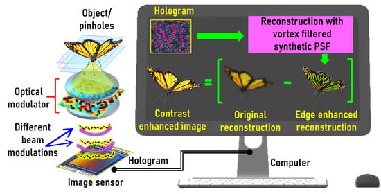
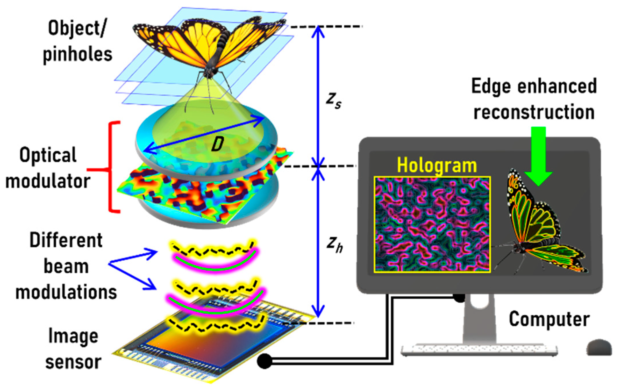
Edge and Contrast Enhancement Using Spatially Incoherent Correlation Holography Techniques

 ,
,  ,
,  , ,
, ,  and
and 
Abstract
1. Introduction
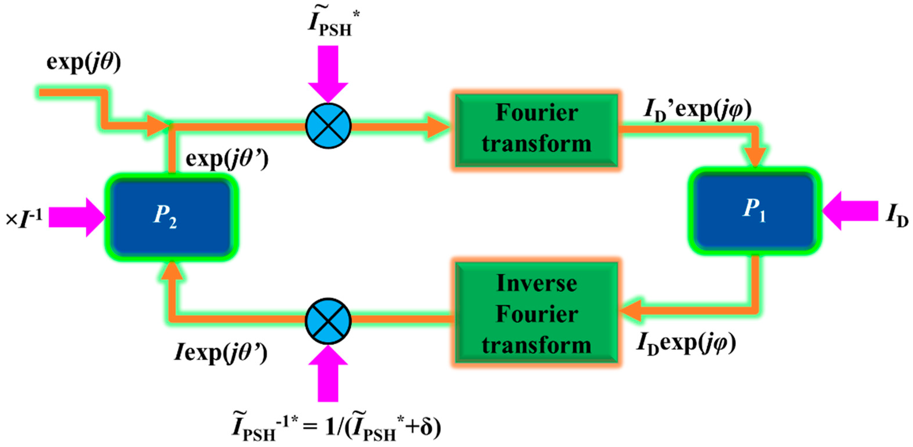
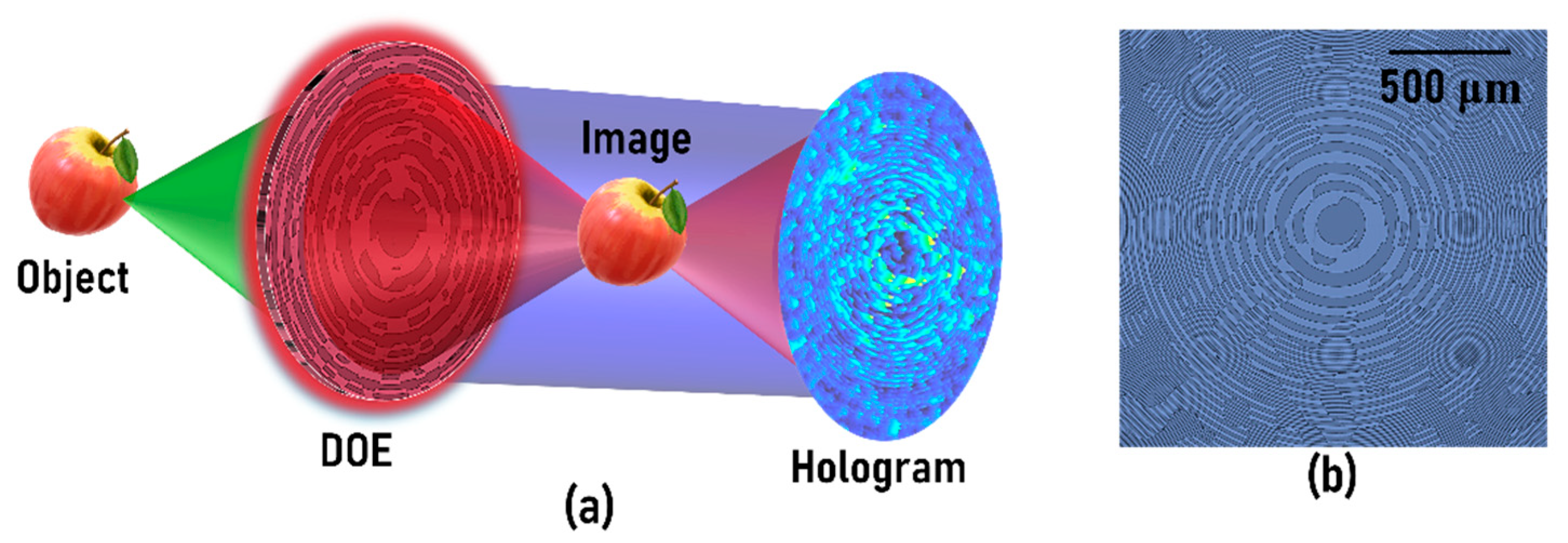
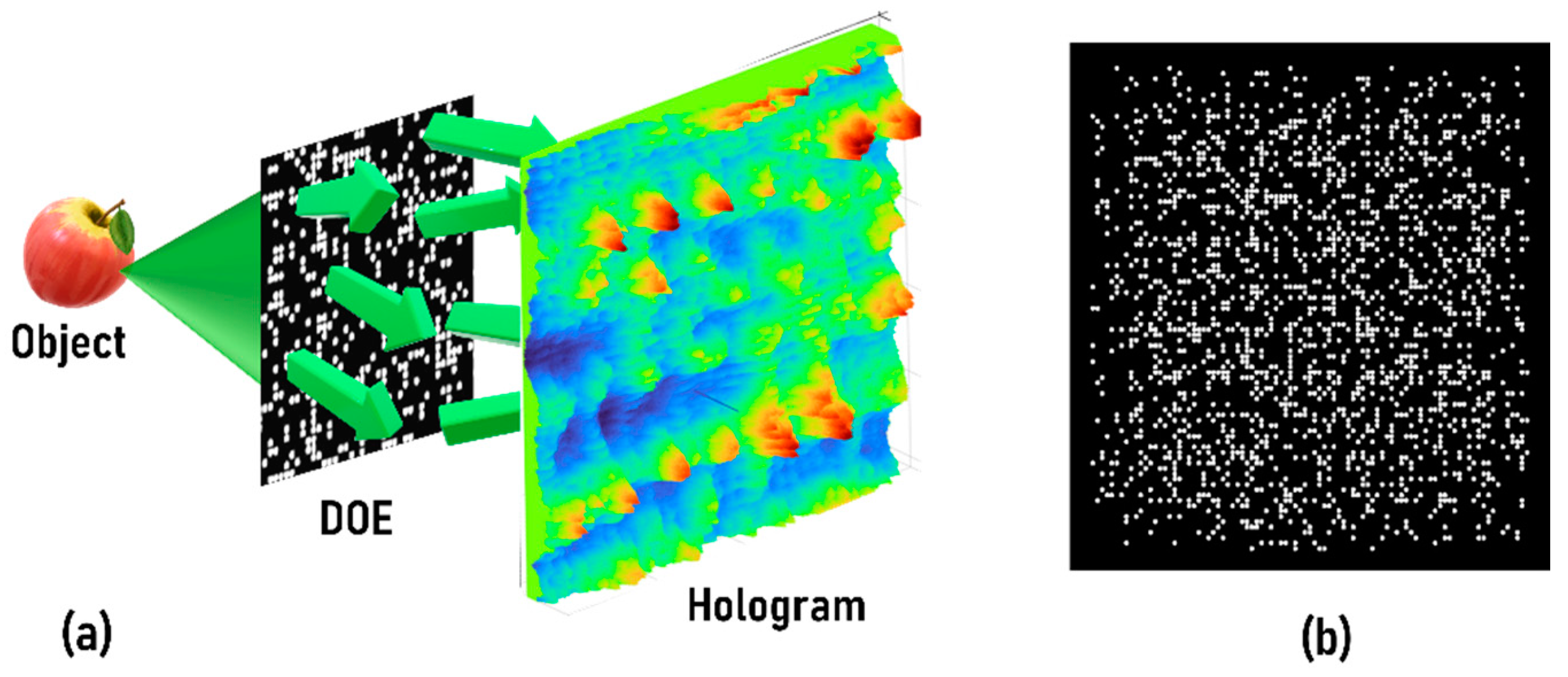
2. Methods
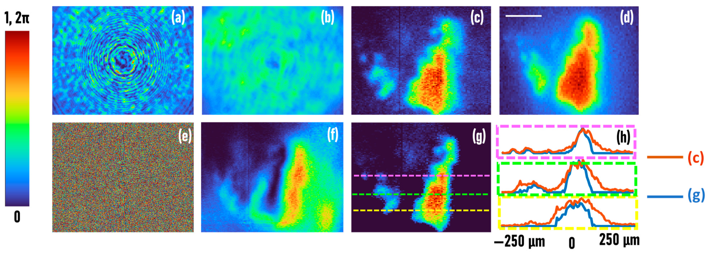
3. Results
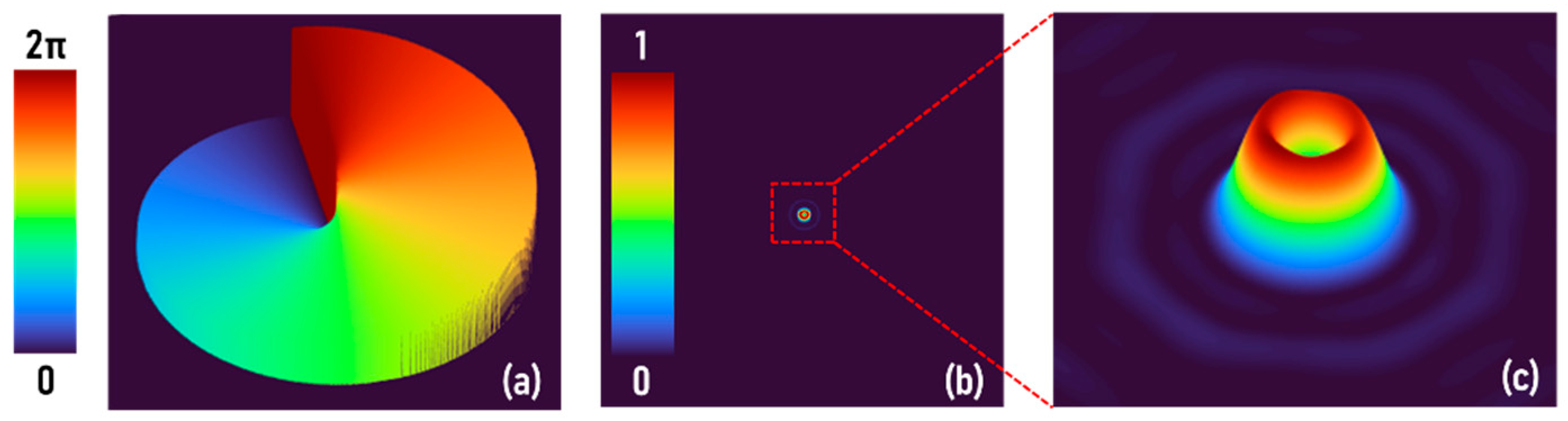
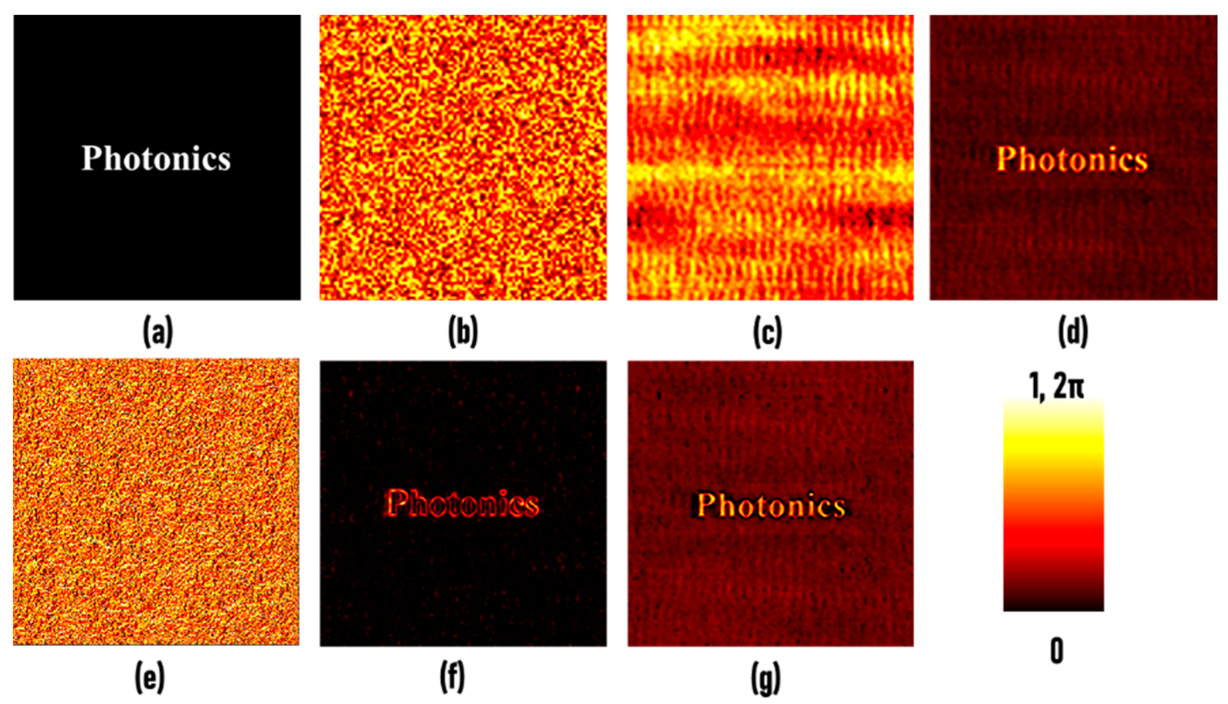
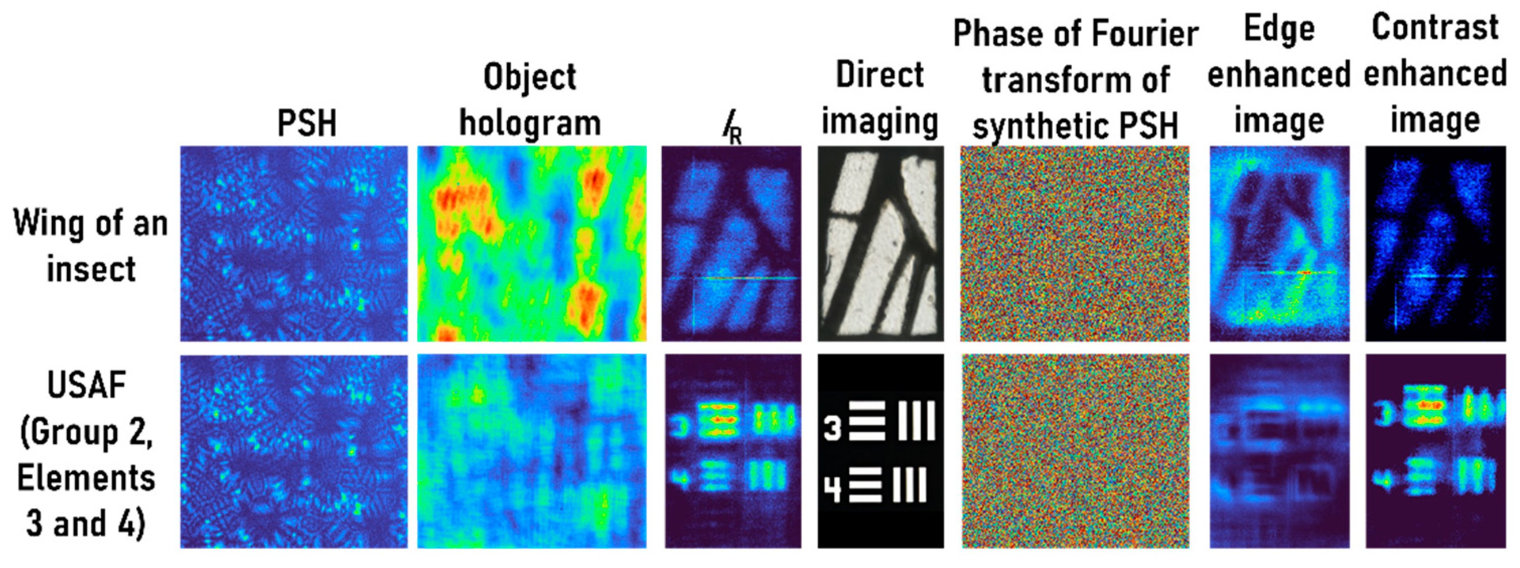
3.1. FINCH
3.2. CAI–Temporally Coherent
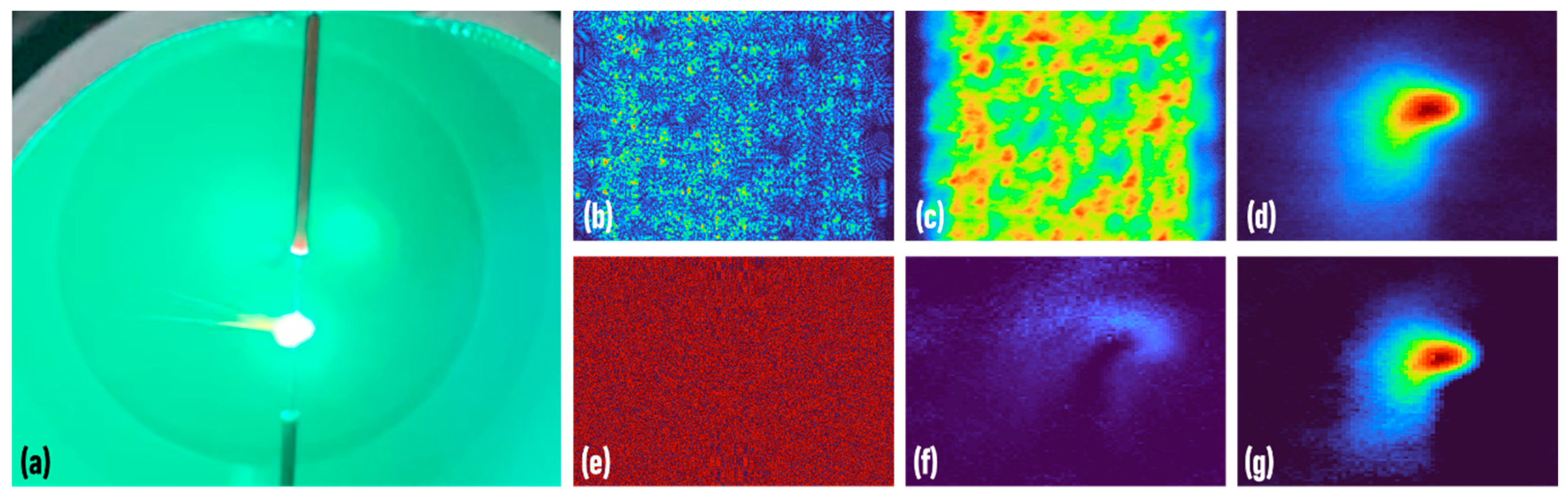
3.3. CAI–Temporally Low-Coherent
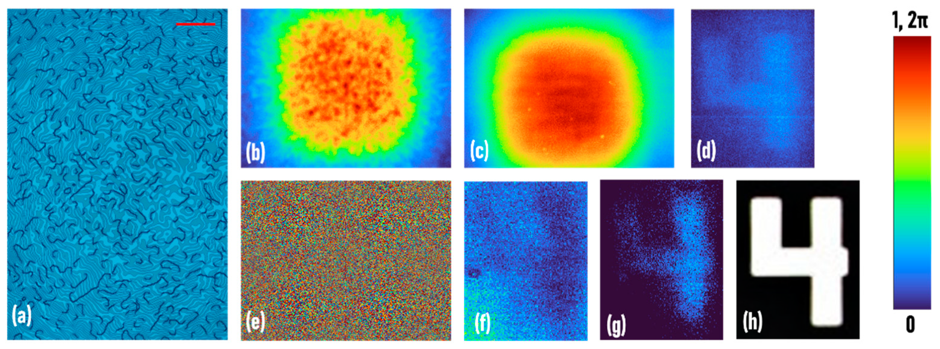
3.4. CAI–Temporally Incoherent
4. Discussion
5. Conclusions
Author Contributions
Funding
Data Availability Statement
Acknowledgments
Conflicts of Interest
References
- Monnin, P.; Bulling, S.; Hoszowska, J.; Valley, J.F.; Meuli, R.; Verdun, F.R. Quantitative characterization of edge enhancement in phase contrast x-ray imaging. Med. Phys. 2004, 31, 1372–1383. [Google Scholar] [CrossRef]
- Yue, Y.; Croitoru, M.M.; Bidani, A.; Zwischenberger, J.B.; Clark, J.W. Nonlinear multiscale wavelet diffusion for speckle suppression and edge enhancement in ultrasound images. IEEE Trans. Med. Imaging 2006, 25, 297–311. [Google Scholar]
- Alonso, M.T.; López-Martínez, C.; Mallorquí, J.J.; Salembier, P. Edge enhancement algorithm based on the wavelet transform for automatic edge detection in SAR images. IEEE Trans. Geosci. Remote. Sens. 2010, 49, 222–235. [Google Scholar] [CrossRef]
- Goodman, J.W. Introduction to Fourier Optics; Roberts and Company Publishers: Greenwood Village, CO, USA, 2005. [Google Scholar]
- Saleh, B.E.A.; Teich, M.C. Fundamentals of Photonics; John Wiley & Sons, Inc.: Hoboken, NJ, USA, 2019. [Google Scholar]
- Sharma, M.K.; Joseph, J.; Senthilkumaran, P. Selective edge enhancement using anisotropic vortex filter. Appl. Opt. 2011, 50, 5279–5286. [Google Scholar] [CrossRef] [PubMed]
- Khonina, S.N.; Kotlyar, V.V.; Shinkaryev, M.V.; Soifer, V.A.; Uspleniev, G.V. The phase rotor filter. J. Mod. Opt. 1992, 39, 1147–1154. [Google Scholar] [CrossRef]
- Wang, J.; Zhang, W.; Qi, Q.; Zheng, S.; Chen, L. Gradual edge enhancement in spiral phase contrast imaging with fractional vortex filters. Sci. Rep. 2015, 5, 1–6. [Google Scholar] [CrossRef] [PubMed]
- Rosen, J.; Brooker, G. Digital spatially incoherent Fresnel holography. Opt. Lett. 2007, 32, 912–914. [Google Scholar] [CrossRef]
- Rosen, J.; Brooker, G. Non-Scanning Motionless Fluorescence Three-Dimensional Holographic Microscopy. Nat. Photonics 2008, 2, 190–195. [Google Scholar] [CrossRef]
- Rosen, J.; Siegel, N.; Brooker, G. Theoretical and experimental demonstration of resolution beyond the Rayleigh limit by FINCH fluorescence microscopic imaging. Opt. Express 2011, 19, 26249–26268. [Google Scholar] [CrossRef] [PubMed]
- Rosen, J.; Brooker, G. Fresnel incoherent correlation holography (FINCH)—A review of research. Adv. Opt. Technol. 2012, 1, 151–169. [Google Scholar] [CrossRef]
- Bouchal, P.; Bouchal, Z. Selective edge enhancement in three-dimensional vortex imaging with incoherent light. Opt. Lett. 2012, 37, 2949–2951. [Google Scholar] [CrossRef]
- Harris, M.; Hill, C.A.; Vaughan, J.M. Optical helices and spiral interference fringes. Opt. Commun. 1994, 106, 161–166. [Google Scholar] [CrossRef]
- Xu, T.; He, J.; Ren, H.; Zhao, Z.; Ma, G.; Gong, Q.; Yang, S.; Dong, L.; Ma, F. Edge contrast enhancement of Fresnel incoherent correlation holography (FINCH) microscopy by spatial light modulator aided spiral phase modulation. Opt. Express 2017, 25, 29207–29215. [Google Scholar] [CrossRef]
- Bu, Y.; Wang, X.; Li, Y.; Du, Y.; Gong, Q.; Zheng, G.; Ma, F. Tunable edge enhancement by higher-order spiral Fresnel incoherent correlation holography system. J. Phys. D Appl. Phys. 2021, 54, 125103. [Google Scholar] [CrossRef]
- Vijayakumar, A.; Rosen, J. Interferenceless coded aperture correlation holography—A new technique for recording incoherent digital holograms without two-wave interference. Opt. Express 2017, 25, 13883–13896. [Google Scholar] [CrossRef] [PubMed]
- Kumar, M.; Vijayakumar, A.; Rosen, J. Incoherent digital holograms acquired by interferenceless coded aperture correlation holography system without refractive lenses. Sci. Rep. 2017, 7, 11555. [Google Scholar] [CrossRef] [PubMed]
- Anand, V.; Ng, S.H.; Maksimovic, J.; Linklater, D.; Katkus, T.; Ivanova, E.P.; Juodkazis, S. Single shot multispectral multidimensional imaging using chaotic waves. Sci. Rep. 2020, 10, 1–13. [Google Scholar] [CrossRef]
- Rai, M.R.; Rosen, J. Noise suppression by controlling the sparsity of the point spread function in interferenceless coded aperture correlation holography (I-COACH). Opt. Express 2019, 27, 24311–24323. [Google Scholar] [CrossRef]
- Antipa, N.; Kuo, G.; Heckel, R.; Mildenhall, B.; Bostan, E.; Ng, R.; Waller, L. DiffuserCam: Lensless single-exposure 3D imaging. Optica 2018, 5, 1–9. [Google Scholar] [CrossRef]
- Wu, Y.; Sharma, M.K.; Veeraraghavan, A. WISH: Wavefront imaging sensor with high resolution. Light Sci. Appl. 2019, 8, 1–10. [Google Scholar] [CrossRef]
- Sekko, E.; Thomas, G.; Boukrouche, A. A deconvolution technique using optimal Wiener filtering and regularization. Signal Process. 1999, 72, 23–32. [Google Scholar] [CrossRef]
- Hojjatoleslami, S.A.; Avanaki, M.R.N.; Podoleanu, A.G. Image quality improvement in optical coherence tomography using Lucy–Richardson deconvolution algorithm. Appl. Opt. 2013, 52, 5663–5670. [Google Scholar] [CrossRef] [PubMed]
- Anand, V.; Katkus, T.; Juodkazis, S. Randomly Multiplexed Diffractive Lens and Axicon for Spatial and Spectral Imaging. Micromachines 2020, 11, 437. [Google Scholar] [CrossRef] [PubMed]
- Anand, V.; Katkus, T.; Lundgaard, S.; Linklater, D.P.; Ivanova, E.P.; Ng, S.H.; Juodkazis, S. Fresnel incoherent correlation holography with single camera shot. Opto-Electron. Adv. 2020, 3, 200004. [Google Scholar]
- Anand, V.; Katkus, T.; Ng, S.H.; Juodkazis, S. Review of Fresnel incoherent correlation holography with linear and non-linear correlations. Chin. Opt. Lett. 2021, 19, 020501. [Google Scholar] [CrossRef]
- Vijayakumar, A.; Kashter, Y.; Kelner, R.; Rosen, J. Coded aperture correlation holography system with improved performance. Appl. Opt. 2017, 56, F67–F77. [Google Scholar] [CrossRef]
- Rai, M.R.; Vijayakumar, A.; Rosen, J. Non-linear adaptive three-dimensional imaging with interferenceless coded aperture correlation holography (I-COACH). Opt. Express 2018, 26, 18143–18154. [Google Scholar] [CrossRef]
- Horner, J.L.; Gianino, P.D. Phase-only matched filtering. Appl. Opt. 1984, 23, 812–816. [Google Scholar] [CrossRef]
- Vijayakumar, A.; Bhattacharya, S. Design and Fabrication of Diffractive Optical Elements with MATLAB; SPIE Press Book: Bellingham, WA, USA, 2017. [Google Scholar]
- Tian, N.; Fu, L.; Gu, M. Resolution and contrast enhancement of subtractive second harmonic generation microscopy with a circularly polarized vortex beam. Sci. Rep. 2015, 5, 13580. [Google Scholar] [CrossRef]
- Korobchevskaya, K.; Peres, C.; Li, Z.; Antipov, A.; Sheppard, C.J.; Diaspro, A.; Bianchini, P. Intensity weighted subtraction microscopy approach for image contrast and resolution enhancement. Sci. Rep. 2016, 6, 25816. [Google Scholar] [CrossRef]
- Rai, M.R.; Vijayakumar, A.; Ogura, Y.; Rosen, J. Resolution enhancement in nonlinear interferenceless COACH with point response of subdiffraction limit patterns. Opt. Express 2019, 27, 391–403. [Google Scholar] [CrossRef] [PubMed]
- Anand, V.; Ng, S.H.; Katkus, T.; Juodkazis, S. Spatio-spectral-temporal imaging of fast transient phenomena using a random array of pinholes. Adv. Photonics Res. 2021, 2, 2000032. [Google Scholar] [CrossRef]
- Anand, V.; Ng, S.H.; Katkus, T.; Juodkazis, S. White light three-dimensional imaging using a quasi-random lens. Opt. Express 2021, 29, 15551–15563. [Google Scholar] [CrossRef] [PubMed]


Publisher’s Note: MDPI stays neutral with regard to jurisdictional claims in published maps and institutional affiliations. |
© 2021 by the authors. Licensee MDPI, Basel, Switzerland. This article is an open access article distributed under the terms and conditions of the Creative Commons Attribution (CC BY) license (https://creativecommons.org/licenses/by/4.0/).
Share and Cite
Anand, V.; Rosen, J.; Ng, S.H.; Katkus, T.; Linklater, D.P.; Ivanova, E.P.; Juodkazis, S. Edge and Contrast Enhancement Using Spatially Incoherent Correlation Holography Techniques. Photonics 2021, 8, 224. https://doi.org/10.3390/photonics8060224
Anand V, Rosen J, Ng SH, Katkus T, Linklater DP, Ivanova EP, Juodkazis S. Edge and Contrast Enhancement Using Spatially Incoherent Correlation Holography Techniques. Photonics. 2021; 8(6):224. https://doi.org/10.3390/photonics8060224
Chicago/Turabian StyleAnand, Vijayakumar, Joseph Rosen, Soon Hock Ng, Tomas Katkus, Denver P Linklater, Elena P Ivanova, and Saulius Juodkazis. 2021. "Edge and Contrast Enhancement Using Spatially Incoherent Correlation Holography Techniques" Photonics 8, no. 6: 224. https://doi.org/10.3390/photonics8060224
APA StyleAnand, V., Rosen, J., Ng, S. H., Katkus, T., Linklater, D. P., Ivanova, E. P., & Juodkazis, S. (2021). Edge and Contrast Enhancement Using Spatially Incoherent Correlation Holography Techniques. Photonics, 8(6), 224. https://doi.org/10.3390/photonics8060224