1. Introduction
Recently, mobile communication has progressed rapidly for high-speed and broadband wireless data access. However, the usable wireless spectra were continuously limited and busy. Furthermore, the visible wavelength spectrum is more than 10,000 times the existing wireless spectrum for future signal access applications [
1]. Hence, the light-emitting diode (LED) based visible light communication (VLC) system has been presented and demonstrated to provide an alternative choice for wide capacity wireless access [
2,
3]. The LED-based VLC transmission could also provide beneficial benefits, such as cost-effectiveness, a large unlicensed spectrum, energy efficiency, a long lifetime, no electromagnetic interference (EMI), high modulation bandwidth, and signal security [
4,
5,
6]. Essentially, the commercial component of phosphor-LED could only provide the achievable bandwidth of 1 to 10 MHz for VLC link, which would limit the data capacity [
7,
8]. To enhance the obtainable VLC capacity, the analog equalization design [
8,
9,
10], parallel VLC architecture [
11], optical color filter [
12], optical multi-input multi-output (MIMO) method [
13,
14], wavelength-division-multiplexing (WDM) [
15,
16] and polarization-division-multiplexing (PDM) technologies [
17,
18,
19,
20] were studied and discussed.
Utilizing 2 × 2 PDM LED-based VLC methods was proposed for doubling data rates in recent years. In 2014, Wang et al. presented 1 Gbit/s orthogonal-frequency-division-multiplexing (OFDM) modulation rate based on a 2 × 2 red-green-blue (RGB) LED-based PDM system [
18]. However, they needed the avalanche photodiode (APD) to detect VLC signals through a free space transmission length of 80 cm. In 2018, Hsu et al. demonstrated a 2 × 2 phosphor LED-based 1.4 Gbit/s OFDM VLC system with a Volterra nonlinear equalization (VNE) method by using PIN PD for detection at the illuminance of 1000 Lux [
19]. Here, the larger illuminance and complex VNE algorithm were required to decode PDM and WDM VLC signal, and the wireless VLC length was not indicated. As mentioned above, they required OFDM modulation format for a shorter VLC connection length (or at the greater illuminance) to achieve >1 Gbit/s data rate. In 2017, Lu et al. presented a hybrid PDM and RGB-WDM VLC system to achieve a 2.16 Gbit/s OFDM rate through 3 m link length within 100 MHz available bandwidth [
20]. However, the related locations of the VLC transmitter (Tx) and receiver (Rx) were both fixed to deliver and decode the VLC signal for indoor application.
In this demonstration, we propose and investigate a PDM-based G- and B-LED VLC transmission system with an orthogonal-polarization state to double the data traffic. Here, to obtain the dual-polarized VLC signals, the two orthogonal polarizers (POLs) at the receiver (Rx) side can be controlled for rotation automatically to match the dual VLC signals from the transmitter (Tx) site. The presented dual-polarized VLC system can achieve the total modulation rate of 1200 and 1120 Mbps (VLC(Green+Blue)) passing through 3 and 4 m free-space transmission lengths, respectively when the detected corresponding illuminances of G- and B-LEDs are 2.4 and 0.5 lux and 5.4 and 2.3 lux. To make the presented LED VLC system more flexible, we also employed paired G-LEDs and B-LEDs acting as the optical transmitter (Tx) to produce dual-polarized VLC(Green) and VLC(Blue) signals for alternative indoor applications, respectively. Hence, the proposed 2 × 2 PDM G- and B-LED VLC system does not need any color filter for decoding signals. When the VLC client is moving randomly, the two polarizers (POLs) of the Rx side are controlled to match the dual-polarized VLC signals and avoid missing received signals. In addition, we also perform and discuss the influence of different polarization offset at a fixed VLC rate through a wireless link length of 3 and 4 m, respectively. Based on the observed results, the largest offset angle of two POLs should be less than 50° to maintain the optimal VLC modulation rate below the forward error correction (FEC) level. The presented LED VLC system is for fully static scenarios in the investigation.
The optical wireless signal indoors might also bring a possibility of occupying by unauthorized stealer. To reach the signal security in the VLC connection, applying the encryption algorithm in the upper layer is one of the methods [
21,
22]. Due to the two mixed VLCs with various modulation formats, it would also generate signal mutual interference to cause a security procedure in the physics layer [
23]. To decode the dual-polarized signals, two orthogonal POLs with precise direction are required at the Rx side. Moreover, if there are many clients with only one Rx detector in the same room for receiving the dual-polarized VLC signal, the polarization of POL at each client can be controlled properly to share the total capacity. As a result, compared with the previous work [
17,
18,
19], the presented 2 × 2 PDM G-B LED VLC system can not only achieve >1120 Mbit/s through 4 m wireless link at very low illuminance status but can also provide signal security in the physical layer when the same color LEDs are used.
2. Proposed VLC Architecture and Experiment
Generally, to obtain a higher VLC data rate via the LED-based device, wavelength-division-multiplexing (WDM) LEDs were proposed and studied [
15,
16]. Hence, the red (R), green (G) and blue (B) LEDs could be used to serve as the optical transmitter (Tx) for WDM VLC transmission at the VLC-Tx side, respectively. Here, the three various modulation signals could be applied to each LED to deliver optical wireless traffic. After a VLC transmission length, the blended WDM RGB signals could be received and decoded by the corresponding optical receiver (Rx), when the RGB filters were in front of each Rx to avoid channel interference at the VLC-Rx side, respectively. However, the optical color filters were needed to choose and match the output spectrum of RGB-LED. Moreover, the achievable VLC rate of R-, G- and B-LEDs depended on their useful modulation bandwidth.
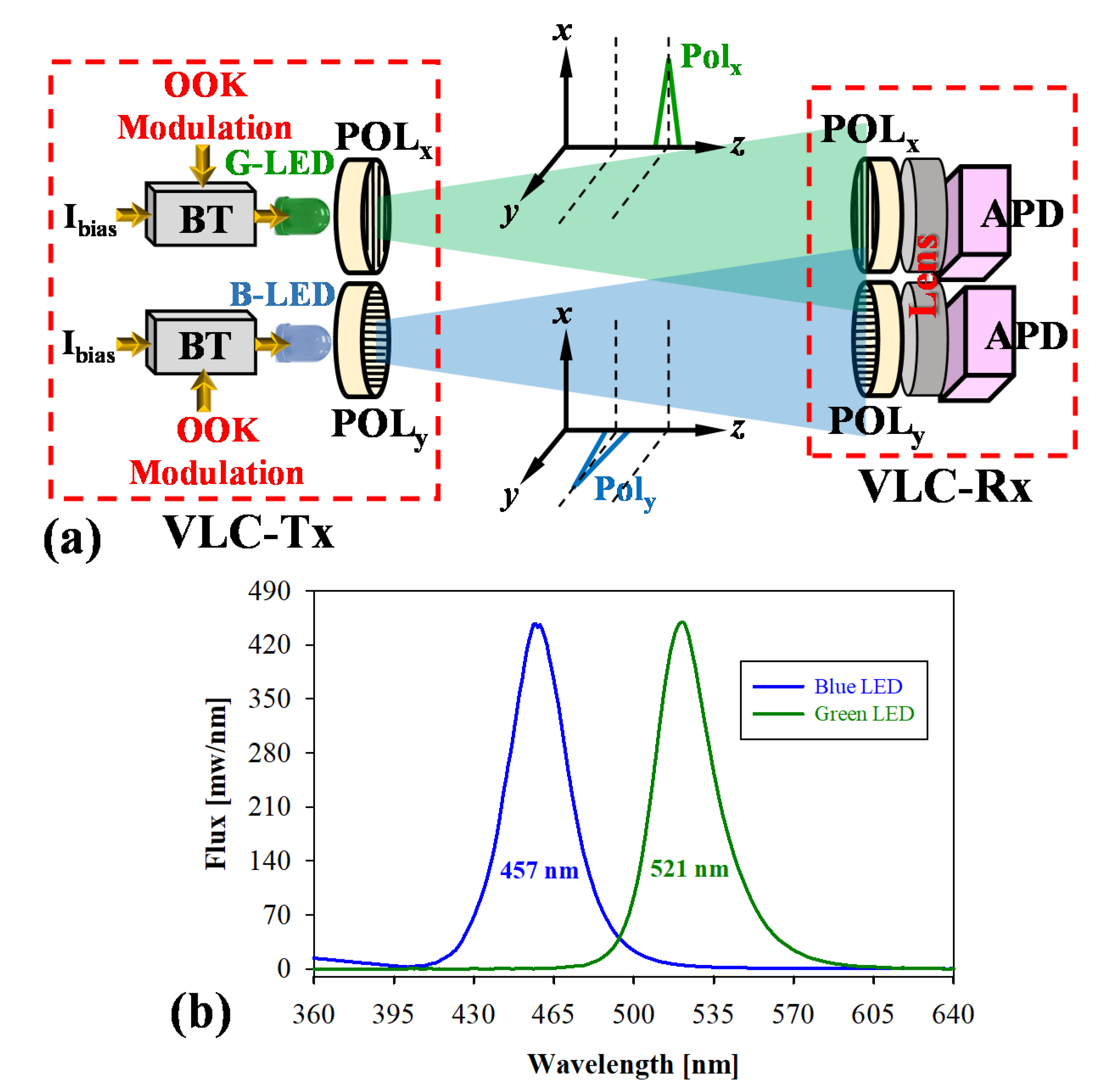
In our demonstration, to achieve a higher modulation capacity of LED-based VLC traffic systems, the G- and B-LEDs with orthogonal polarization are applied at the VLC-Tx, as illustrated in
Figure 1a. Here, the G- and B-LEDs are utilized simultaneously serving as the wireless VLC signal. To deliver two various VLC modulations on the G- and B-LEDs, respectively, two bias-tees (BTs) are used to connect the individual LED and VLC modulation format, when the proper bias currents (I
bias) are applied simultaneously. In addition, two optical polarizers (POLs, 400−700 nm) are placed in front of the G- and B-LEDs to produce orthogonal x- and y-polarization status and avoid the interference of two VLC signals, respectively, as shown in
Figure 1a. Through a length of optical wireless transmission, two wireless green and blue VLC signals (VLC
(Green) and VLC
(Blue)) with orthogonal polarization can be received by the two 400 MHz avalanche photodiodes (APDs) at the VLC-Rx side, respectively. To enhance two detected VLC power and corresponding VLC signals, the two focusing lenses and POLs are also exploited for VLC demodulation, respectively. To improve the detected power sensitivity of the VLC signal, the APD is applied for signal demodulation. Commonly, the indoor illuminance is between 300 and 750 lux, sometimes the illuminance will be lower. So, to detect and decode the VLC signal effectively under a longer wireless length at a lower or extra-low illuminance indoors, the APD-PD can be applied in an LED VLC system as an alternative. Although APD is expensive, it is another option in the VLC system. As a result, the proposed G and B-LED VLC transmission system could double the traffic rate by utilizing dual-polarized VLC channels. However, the two POLs at the VLC-Rx must match the x- and y-polarization directions of the VLC
(Green) and VLC
(Blue) signals. Commonly, the offset of x- and y-polarizations of POL
x and POL
y would result in different insertion losses when the VLC-Rx module moves arbitrarily. In previous studies [
17,
18,
19,
20], there was no mention of VLC problems caused by different offset angles. Therefore, in the proposed VLC-Rx module, to detect the two orthogonal VLC signals from the VLC-Tx completely, two rotatable dual-polarized POLs can be controlled automatically based on the maximum received illuminance for decoding VLC data. Moreover, to examine the bit error rate (BER) performance of the proposed LED VLC system, a BER tester is applied for signal measurement.
3. Result and Discussion
In the experiment, the bias currents of the G- and B-LEDs are both operated at 10 mA. The measured output spectra of the G- and B-LEDs are also shown in
Figure 1b. We observed that the central wavelengths of G- and B-LEDs are 457 and 521 nm, respectively. To reach a broader modulation bandwidth of LED, an analog front end (AFE) circuit with pre-equalization was also designed to carry various on-off keying (OOK) modulation signals for delivering VLC traffic at the VLC-Tx [
6,
8]. In addition, to enhance the detected VLC illuminance, two focusing lenses with 5 cm diameter were also in front of the two APDs, as exhibited in
Figure 1a. Due to the smaller I
bias on each LED, the demonstrated LED VLC system also can achieve better energy efficiency.
In the demonstration,
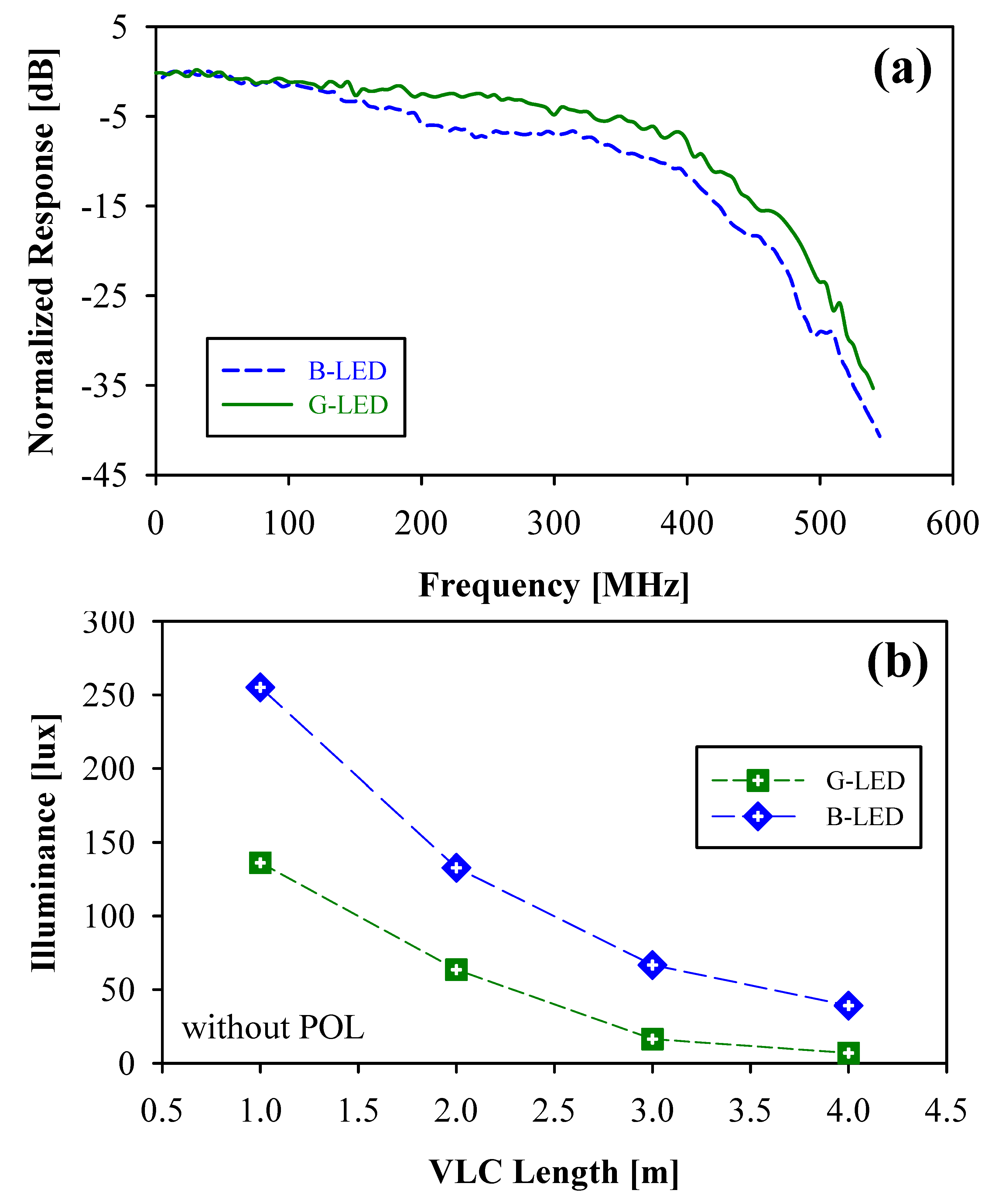
Figure 2a is the effective bandwidth measured by G-LED and B-LED itself by using the 400 MHz bandwidth APD, respectively. Here, the corresponding detected bandwidths of G- and B-LEDs are nearly 415 and 380 MHz within a 10 dB bandwidth range, respectively. This is due to the limitation of the original 400 MHz APD. According to the achieved results of
Figure 2a, the modulation rate of the G- and B-LEDs should be able to reach 400 Mbit/s initially. The valuable bandwidth of the G-LED is better than that of the B-LED in the observation. Furthermore, the original illuminances of the G- and B-LEDs are also detected under various VLC transmission lengths before entering the POL or color filter, respectively, as schemed in
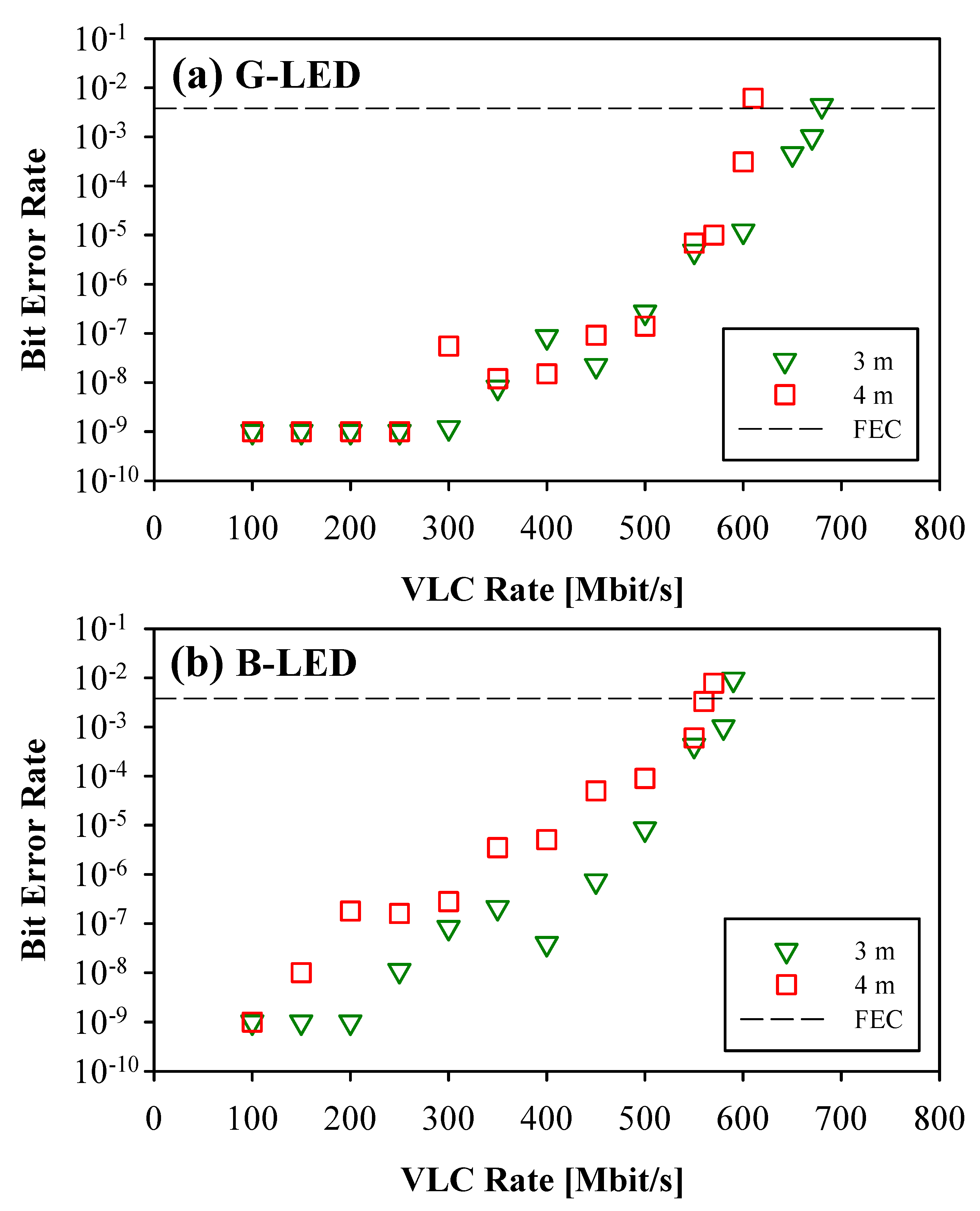
Figure 2b. The detected illuminances of the G- and B-LEDs are between 7 and 136.1 lux and 39.1 and 255.1 lux, respectively, under the free space connection lengths of 1 to 4 m. First, we executed the bit error rate (BER) performances of WDM G- and B-LEDs through 3 and 4 m VLC connections, respectively, when the POLs are not used and the corresponding color filters are applied in the measurement. Here, the greatest OOK modulation rates of G- and B-LEDs was 670 and 580 Mbit/s and 600 and 560 Mbit/s at the forward error correction (FEC) limit (BER ≤ 3.8 × 10
−3) through 3 and 4 m VLC link lengths, respectively, when the pre- and post-equalizations are applied on the Tx- and Rx-VLC sides, as shown in
Figure 3a,b. We only used 400 MHz APD with an equalization circuit in the presented VLC system to decode 670 Mbit/s OOK signal. These have two benefits, the first one can reduce costs, and the other one can increase the decoding bandwidth in the demonstration.
Second, we performed the proposed dual-polarized VLC system through different free-space transmission lengths. Hence, the corresponding illuminances of the G- and B-LEDs after passing through two POLs with parallel polarization before launching into the focusing lens were measured first.
Figure 4 displays the detected illuminance of the G- and B-LEDs after a free-space link length of 1 to 4 m, respectively. The achievable illuminances of the G- and B-LEDs are obtained between 0.5 and 22.7 lux and 2.3 and 31.9 lux, respectively, as seen in
Figure 4. Here, to establish the long indoor VLC transmission length, we selected 3 and 4 m links for the VLC
(Green) and VLC
(Blue) connections, respectively.
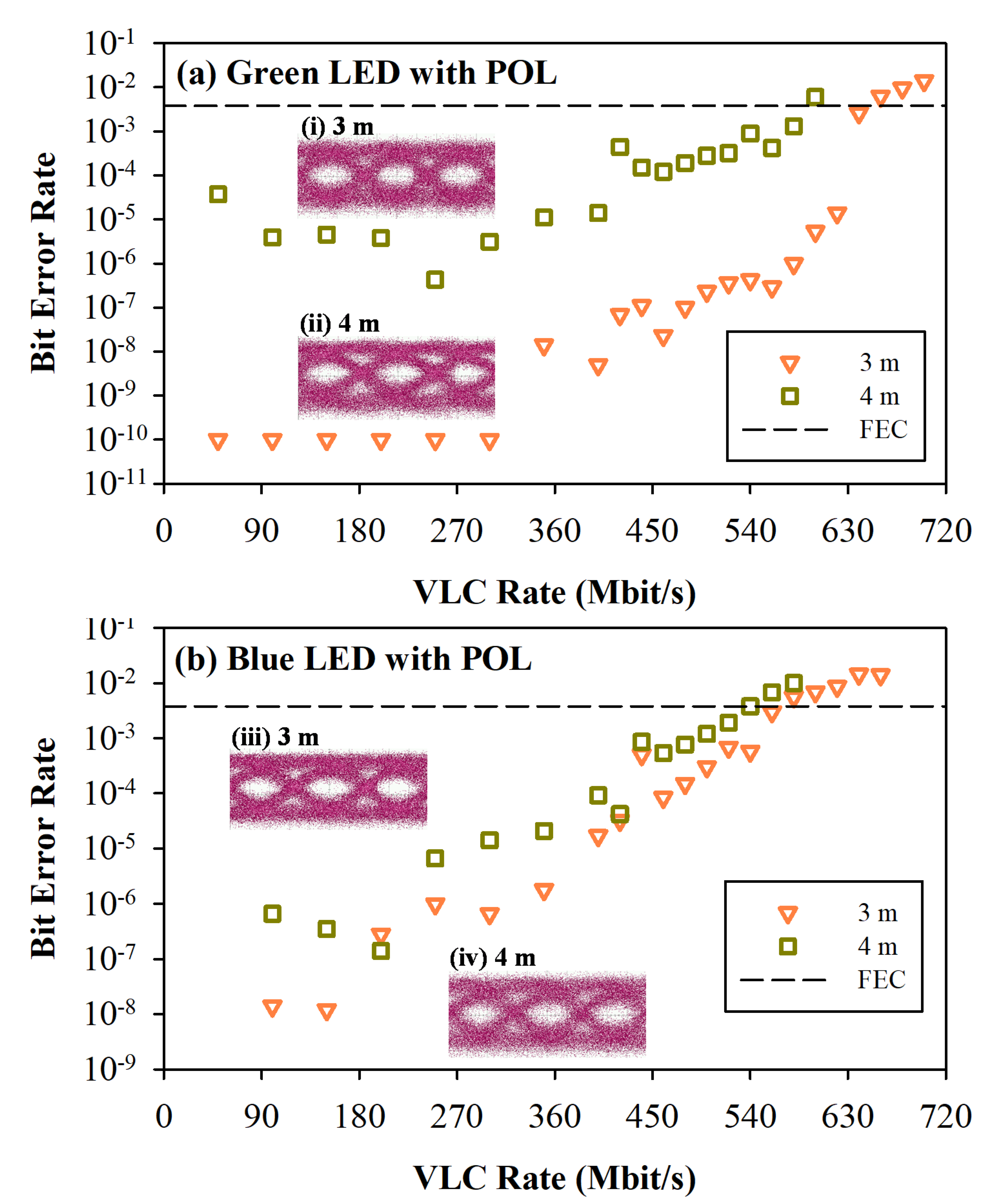
Figure 5a,b exhibit the obtained bit error rate (BER) performances of the VLC
(Green) and VLC
(Blue) traffics versus various OOK modulation rates after an optical wireless transmission length of 3 and 4 m, respectively. In the measurement, the largest VLC
(Green) data rates of 640 and 580 Mbps were achieved below the forward error correction (FEC) threshold (BER of 3.8 × 10
−3), respectively, through a wireless link of 3 and 4 m, when the corresponding illuminances were 2.4 and 0.5 lux (before entering the lens), as shown in
Figure 5a. The insets of (i) and (ii) of
Figure 5a are the corresponding eye diagrams at the 640 and 580 Mbps, respectively. Identically, the OOK VLC
(Blue) traffics could also reach 560 and 540 Mbps after 3 and 4 m free-space transmissions to satisfy the FEC target under the corresponding illuminances of 5.4 and 2.3 lux, respectively, as illustrated
Figure 5b. The insets of (iii) and (iv) of
Figure 5b are the measured eye diagrams at the 560 and 540 Mbps VLC
(Blue) rates, respectively. As displayed in
Figure 5a,b, the modulation rate of the G-LED seems better than that of B-LED due to the characteristics of the component itself. According to the presented dual-polarized G- and B-LED VLC system, the largest VLC traffics of 1200 Gbps (640
(Green) + 560
(Blue) Mbps) and 1120 Mbps (580
(Green) + 540
(Blue) Mbps) were obtained under 3 and 4 m free-space link lengths, respectively, when the equalization method was applied on the AFE side under the very low illuminance for decoding data.
In the demonstration, we could not only apply two various color LEDs in the presented dual-polarized VLC system but also we could utilize two same color LEDs. We could also utilize a pair of polarization-multiplexing G-LEDs (or B-LEDs) at the VLC-Tx for delivering wireless VLC traffics. Therefore, the maximum dual-polarized G-LED VLC
(Green) and B-LED VLC
(Blue) rates of 2 × 640 and 2 × 580 Mbps; and 2 × 560 and 2 × 540 Mbps were achieved after 3 and 4 m optical wireless connections, respectively. This means that we can arbitrarily use the combination of two LEDs for dual-polarized VLC transmission. Moreover, the observed BER measurements of dual-polarized VLC
(Green) and VLC
(Blue) under different modulated rates were similar to
Figure 5a,b, therefore we do not exhibit the BER measurements here. As mentioned above, this means that we can arbitrarily use the combination of two LEDs for dual-polarized VLC transmission.
According to the results of
Figure 4 and
Figure 5, the achieved largest VLC rate depends on the detected illuminance. The obtained VLC power would affect the signal performance. As the VLC transmission length increases, the available signal capacity will be relatively smaller, due to the weaker corresponding detected power. Therefore, a >1 Gbit/s OOK rate through a 4 m wireless connection can be achieved in the proposed dual-polarized LED VLC system.
However, while the polarization of two orthogonal POLs is offset at the VLC-Rx, the obtained VLC signal would be influenced and interfered with due to two mixed VLC traffics. To avoid this problem, the two POLs can be controlled for rotation automatically based on the maximum detected illuminance. In the investigation, we demonstrate and discuss the VLC performance of the G- and B-LEDs under the different offset angles. For example, according to the measured results of
Figure 5a, we select the 620 and 440 Mbps OOK modulations under the free-space link of 3 and 4 m for VLC
(Green) BER demonstration when the various rotation angle of POL is changed gradually.
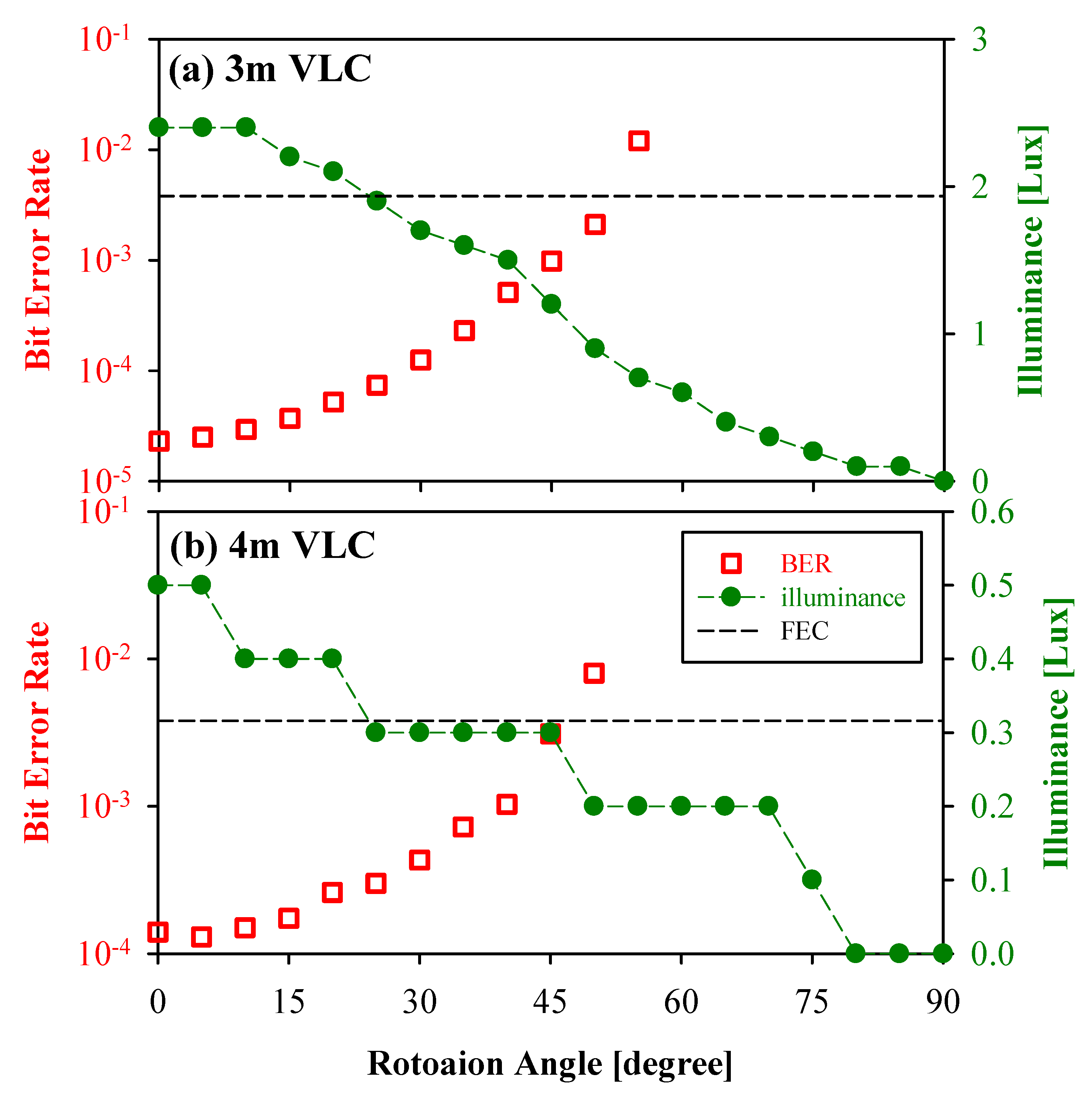
Figure 6a,b present the observed BER performances of G-LED versus the various rotation angles of 0° to 90° with the corresponding illuminances of 0 to 2.4 lux and 0 to 0.5 lux, respectively. To meet with the VLC
(Green) traffic below the FEC threshold, the offset angles must be small than 50° and 45°, respectively, after 3 (illuminance = 0.9 lux) and 4 m (illuminance = 0.3 lux) optical wireless transmissions, as illustrated in
Figure 6a,b.
Next, to understand the effect of offset angle for the B-LED-based VLC traffic, we applied 520 and 500 Mbps OOK VLC signals for the BER measurements under various offset angles according to the obtained results of
Figure 5b. Therefore,
Figure 7a,b exhibit the observed BER presentations of B-LED versus the various rotation angles of 0° to 90° under the corresponding illuminances of 0 to 5.4 lux and 0 to 2.4 lux, respectively. To fit the VLC
(Blue) signal below the FEC threshold, the offset angles must be small than 45° and 35° after 3 (illuminance = 1.6 lux) and 4 m (illuminance = 2.9 lux) free-space connections, as demonstrated in
Figure 7a,b.
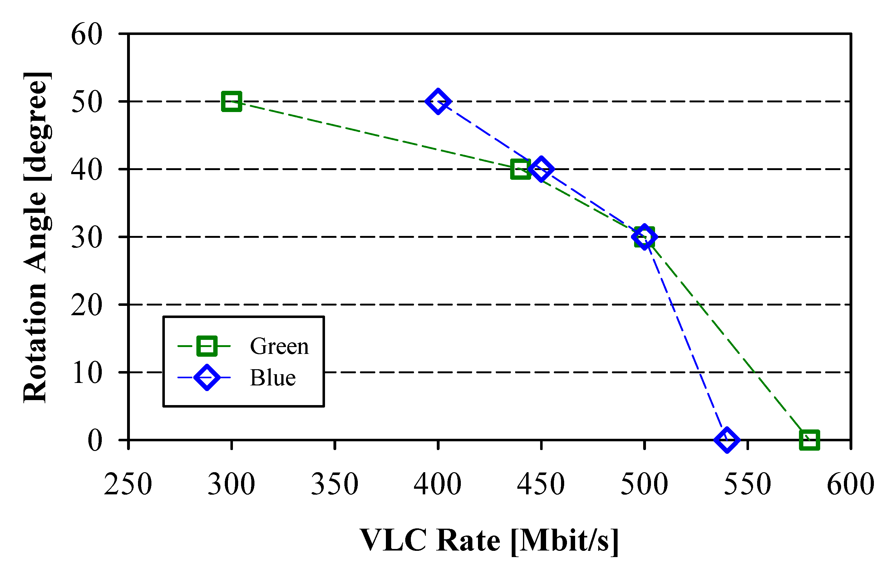
The influence of the offset angle on the maximum VLC modulation rate is also a critical issue. As mentioned above, the maximum VLC modulation rates are 580 and 540 Mbps for the G- and B-LED VLC transmissions under a 4 m free-space link, respectively. In the measurement, when the offset angle of POL is increased gradually from 0° to 50°, the corresponding largest modulation rates of G- and B-LED VLC traffics can be obtained within the FEC target, as shown in
Figure 8. In this measurement, the maximum G-LED VLC of 500, 440 and 300 Mbps are achieved under the offset angle of 30°, 40° and 50°, respectively. The 500, 450 and 400 Mbps traffics of B-LED VLC link are also observed under the offset angle of 30°, 40° and 50°, respectively. This is because the illuminance of the G-LED itself is smaller than that of the B-LED. Once the angle is over 50°, the VLC
(Green) and VLC
(Blue) traffics would be not obtained due to the larger insertion loss. Therefore, the results show that the corresponding illuminances of the G- and B-LEDs must be greater than 0.2 and 1 lux to obtain optimal VLC performance through a 4 m free-space connection. As exhibited in
Figure 8, we can obtain the same data rate of 500 Mbps for the VLC
(Green) and VLC
(Blue) connections, when the offset angle is rotated at 30°. In addition, with a gradual increase in the offset angle, the measured modulation signal of the B-LED would also be larger than that of the G-LED.
In the demonstration, owing to two blended orthogonal VLC signals, the VLC traffic also can provide security operation in the physical layer based on channel interference if the polarization of the POLs are not matching. In our previous study [
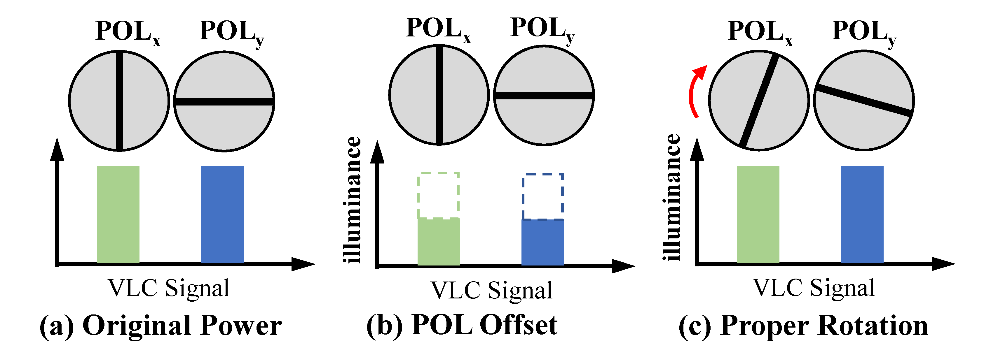
23], the two mixed VLC signals with similar power would cause very serious data interference. To decode the dual-polarized VLC signals, two orthogonal POLs with precise direction controls are required at the VLC-Rx side, when the client is in a state of arbitrary movement. The control of the POL is dependent on the maximum detected illuminance for proper rotation. The schematic diagram of the control design is illustrated in
Figure 9 for proof of concept. Hence, the corresponding VLC signal can be detected through proper rotation. Additionally, if there are many clients with only one Rx detector in the same room for receiving a dual-polarized VLC signal, the polarization of the POL for each client can be adjusted properly to share and adapt the total capacity. Therefore, the proposed dual-polarized LED VLC system can not only double the data rate but can also provide a security function according to the polarization-based filter.
