Abstract
The powersphere is a device used for maximizing the conversion of light in wireless energy transmission via laser. It is a spherical structure made up of thousands of photovoltaic cells. Due to the large dimensions and existence of many holes in the spherical surface, there are some drawbacks in machining, such as limited movement space of the machines, long cycle, low precision, and high cost. In this context, with a powersphere irradiated by the laser as the model, the principle of powersphere is deduced theoretically. It is proven that the illuminance value at any position on the inner wall of the powersphere is equal, and the calculation formula of this value is derived. Based on this theory and the comparative analysis of processing methods and the results of processing experiments, the structure of the powersphere is designed. The experimental processing of the powersphere is carried out by selecting the welding method. Finally, two hemispherical powersphere frames are processed, which are connected by screws to form a ball frame for the installation of photovoltaic cells. The results show that the improved design and fabricating method can process the powersphere quickly, accurately, and economically. A comparative experiment of powersphere and photovoltaic panel was carried out. The experimental results show that the powersphere has the function of light uniformity and repeated use of laser. So, the designed and processed powersphere is consistent with the theoretical analysis.
1. Introduction
With the development of laser technology, the long-distance energy transmission of lasers has gradually shown its technical advantages, with some applications in certain special fields. References [1,2,3,4] pointed out that the wireless energy transmission via laser has the advantages of long transmission distance, small transceiver device, better operational flexibility, user friendliness, and so on. References [5,6,7,8,9] have reported that it can be used in spacecraft, unmanned aerial vehicle, unmanned boats, robot, electric vehicle, and other specific fields. However, the laser intensity distribution is non-uniform, resulting in serious energy loss of the photovoltaic receiving device. The experimental results show that the energy loss can be as high as 78%. The low efficiency of photovoltaic receivers greatly limits the practical applications of laser wireless energy transmission technology [10,11,12].
In order to improve the receiving efficiency, researchers proposed to change the structure of the photovoltaic receiver. References [13,14] proposed to change the conventional flat structure to a spherical one that is called a powersphere. The powersphere is actually a hollow sphere. The closed sphere structure seals the incident laser light in the cavity to prevent it from escaping. The laser is reflected multiple times on the surface of the photovoltaic cell so that the illuminance at any point on the powersphere is equal, which is beneficial to improving the energy output efficiency of the wireless energy transmission via laser.
Most photovoltaic cells use glass as the protective layer, which prevents photovoltaic cells from directly bending into a spherical structure. This requires the use of a number of small-size photovoltaic cells spliced into a sphere. At the same time, for maximum light conversion efficiency, the size of the powersphere also needs to be very large, such as 1 m or even more. This large-sized, irregular-shaped part does not have enough processing scope for conventional metal cutting equipment and three-dimensional (3D) metal printing equipment. Although large-scale gantry processing equipment can be used to make it, the manufacturing cost is high, manufacturing cycle is long, and the precision is low. In order to carry out the next step of related research, it is necessary to carry out the theoretical derivation of the powersphere, and design and manufacture a prototype. The prototype can be used to carry out comparative experiments between the powersphere and the traditional photovoltaic panel to verify the function and effect of the powersphere in wireless energy transmission via laser.
2. Basic Principle of Powersphere
As shown in Figure 1, the radius of the powersphere is R. The laser with a luminous flux of Φ is incident into the powersphere from the entrance hole and irradiates on the inner wall of the powersphere, with a direct irradiation area of S. The directly irradiated light is reflected by the inner wall and transmitted to the other inner walls of the powersphere. The laser finally forms a uniform distribution after multiple reflections on the inner wall [15,16,17,18].
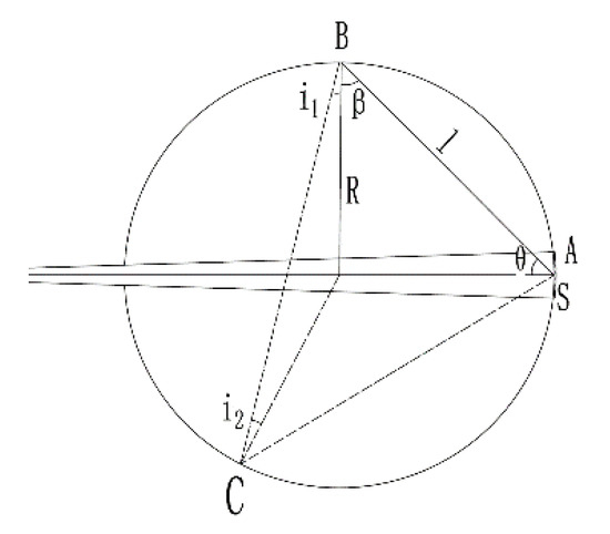
Figure 1.
Principle of powersphere.
Assuming the small surface element of any point in the direct irradiation area S is dA, and the luminous flux irradiated on the surface element is dΦ, then the illumination EA at point A is:
The laser irradiated on the surface element dA is partially absorbed by the inner wall, and the rest is reflected by the inner wall. The reflection coefficient of the inner wall is ρ. At this time, the surface element dA is considered as a light source that can emit light. The beam emitted by the light source is the reflected waves on the surface element dA. The laser emitted by this light source will be transmitted anywhere on the inner wall besides itself. Then, the illuminance of its outward radiation is ρEA. According to the definition of luminance, the luminance LA at point A should be:
where θ is the angle between the normal of the surface element dA and the line connecting AB.
Then, for the surface element dB on any point B on the inner wall, the luminous flux directly irradiated by the surface element dA at point A is:
where dΩ is the solid angle corresponding to the surface element dB,, β is the angle between the normal of the surface element dB and the line connecting AB, then:
According to the geometric properties of the sphere (Figure 1), θ = β, l = 2Rcosθ, and taking the above formula, we get:
Then, the illumination EB at point B is:
Taking (1) and (2) into Equation (6), then we have:
Integrate the above formula, then the sum of the illuminance of the laser directly transmitted waves from point S to point B is:
In addition to these lasers that directly irradiate to B point, there are also many lasers that reflect from point A to other points on the inner wall of the powersphere, and then reflect to point B after multiple reflections. Suppose the laser transmitted from point A directly irradiates point C on the inner wall of the powersphere. The laser transmitted to point C is reflected again and reaches B point. Then, the small surface element dC at point C produces a first illuminance at point B, as follows:
where L0 is the luminance of point C, and the expression is as follows:
where E0 is the direct illumination of point C, equaling to the direct illumination of point B, then Formula (9) becomes:
According to Formula (11), the total first illuminance E1 of all reflected lasers through the inner wall of the powersphere and illuminated to point B is:
Because the divergence angle of the laser is small, the light spot size changes very little during the transmission process, so the required incident hole is very small. Then, S1 in the formula can be approximately expressed as the total area of the inner wall, i.e., E1 = ρEB. When the laser reflected n times by the inner wall of the powersphere irradiates point B, the illuminance of point B is En = ρnEB. So, the total illumination at point B is:
where ρ is less than 1. When n approaches infinity, ρn ≈ 0. Therefore, the total illumination at point B is:
Substituting Formula (8), the total illumination is:
It can be seen from the illuminance formula that the illuminance at any position on the inner wall of the powersphere is equal, and the value E is proportional to the total luminous flux of the incident laser [19,20,21,22].
3. Design and Processing
During the actual process of using the powersphere, other devices must be installed, destroying the ideal conditions of the powersphere. In addition, a part of the energy irradiated by the laser on the photovoltaic cell will be converted into heat, which will cause the photovoltaic cell temperature to increase and the photoelectric conversion efficiency to decrease. To ensure that the error caused by the internally installed device is not too serious, and to slow the rise in temperature inside the powersphere, the powersphere size must be sufficiently large. Of course, to avoid having a luminous flux on the photovoltaic cell that is too weak, the size of the powersphere cannot be too large. Furthermore, the size of the powersphere is also related to the size of the laser incident hole. The diameter of the normal powersphere should be 10–20 times the hole size. Based on the spot size of the laser after long-distance transmission, the design requirements of a powersphere will have an entrance hole diameter of 100 mm and a powersphere diameter of 1000 mm, and the inner wall of the powersphere will be spliced with 20 × 20 mm photovoltaic cells.
According to these requirements, the powersphere structure is designed as shown in Figure 2. The spherical powersphere is composed of two hemispheres. The top of the sphere has a hole with a diameter of 100 mm for laser input. The rest of the sphere is made up of square step holes with a thickness of 3 mm. The large square in the step hole is 20 × 20 mm and the thickness is 2 mm. The small square in the step hole is 18 × 18 mm and the thickness is 1 mm. Therefore, the working surface of the photovoltaic cell faces the inside of the ball, and the installation surface is located on the small square. The distance between the step holes is determined by the number of step holes of the corresponding diameter, but no less than 3 mm. The 20 × 20 mm photovoltaic cells were inserted into the stepped holes to form the inner surface of the powersphere.
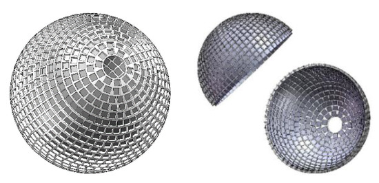
Figure 2.
The structure of the powersphere.
According to the designs, there are three manufacturing methods available: The first is 3D printing. When considering heat dissipation, one must use metal 3D printing. However, the commonly used 3D metal printing size is less than one meter. Moreover, the manufacturing cost is very high, and the manufacturing cycle would be too long.
The second method is by using laser cutting for producing holes and stamping to form spherical surfaces, followed by welding pieces into a sphere, as shown in Figure 3. Figure 3a shows the square step holes cut by the laser on a flat plate. Figure 3b shows a partial sphere with a diameter of 1 m formed by stamping. Finally, multiple pieces are welded and spliced into an entire sphere. It is difficult to cut the step holes using this method, and the stamped holes on the edge of the spherical surface will be deformed. As shown in Figure 4, the square holes on the edge of the sphere have become parallelograms after stamping, and even the size of the holes has changed, so the manufacturing quality cannot be guaranteed.
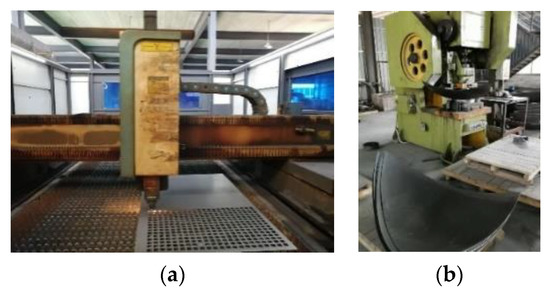
Figure 3.
Method of laser cutting, stamping and welding. (a) Laser cutting, (b) stamping.
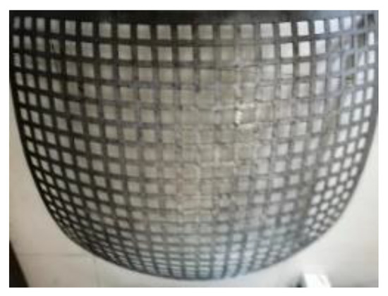
Figure 4.
The deformed holes after stamping.
The third method is to produce hemispheres by spinning or casting, and then to manufacture step holes on the hemispheres. Figure 5 shows typical cased hemispheres. The difficulty associated with this fabrication method is that the datum needs to be re-positioned whenever a hole is machined. The positioning of the spherical surface involves the movement of the three coordinate axes. Because the powersphere has nearly 10,000 holes, it takes too long to process. Second, there are particular requirements for the equipment. Five-axis manufacturing equipment is usually required. The manufacturing range of commonly used five-axis machining centers or laser cutting equipment is very small, so it is quite hard or even impossible to process work pieces with a diameter of approximately 1 m. Therefore, the manufacturing of large-sized work pieces requires large-scale five-axis gantry fabrication equipment, which has high costs and long cycles.
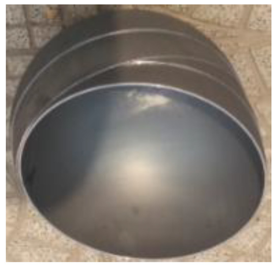
Figure 5.
The cased hemispheres.
Considering the above difficulties involved in manufacturing powerspheres, the original design was modified, as shown in Figure 6. The powersphere is composed of two hemispheres. With this new design, iron bars are welded to form a hemispherical frame with a diameter of 1003 mm. Iron rings of different diameters are then welded in the direction of the vertical sphere frame. The iron ring is bent from a rectangular iron plate with a width of 10 mm and a thickness of 3 mm. The small iron bars with a width of 1 mm and a thickness of 3 mm are welded in the middle of the iron rings. The distance between adjacent small iron bars is 20 mm. In this way, circular grooves with a width of 20 mm and a depth of 3 mm are formed between adjacent small iron bars. Multiple 20 × 20 mm photovoltaic cells can be inserted into circular grooves to form circular photovoltaic belts. Circular photovoltaic belts with different diameters are ultimately combined to form a powersphere.
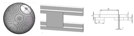
Figure 6.
Modified powersphere design.
4. Manufacturing Experiment
The manufacturing experiment was carried out according to the new design, as shown in Figure 7. In the experiments, an iron plate with a thickness of 3 mm and a width of 30 mm was bent into a 1/4-round workpiece with a diameter of 1003 mm. The cut grooves are made at positions where the welding iron rings are needed on the workpiece. The grooves facilitate the positioning and fixing of the iron rings. Thus, it is beneficial to the operation of welding. Then, the 1/4-round workpieces were welded together to form a hemispherical frame.
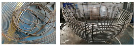
Figure 7.
The manufactured hemispherical frame.
According to the calculated size, the iron plate with a width of 10 mm and the thickness of 3 mm is bent into a corresponding iron ring. Next, the iron rings are welded. During the welding process, one end of the iron ring is welded to the groove of the ball frame. With this method, the iron ring is successively welded to the ball frame in the direction of circular rotation, and finally the other end of the iron ring is welded with the starting end of the iron ring. This processing sequence in the welding process is conducive to the continuous correction of machining errors. After the installation of the iron ring, the small iron bar with a width of 1 mm and a thickness of 3 mm is welded to the middle of the ring, which is used as the mounting frame of photovoltaic cells. In order to ensure that the photovoltaic cell can be installed well, the surface of the mounting frame must be smooth, so the impurities around the welding position of the iron rings and the small iron bars need to be polished. At this point, the hemisphere frame shown in Figure 8a is finally manufactured. On the iron ring of the largest diameter of the hemisphere frame, another iron ring for the connection of two hemispheres was welded in the direction of the vertical hemisphere frame surface. This iron ring (also called link ring) is used to connect the hemispheres. The holes are evenly distributed along the circumferential direction of the link ring. Screws were installed in the screw holes to tightly fix the two hemispheres together. In this way, the two hemispheres form a ball frame as shown in Figure 8b, which can be used to mount photovoltaic cells.
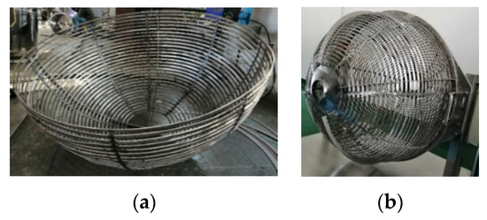
Figure 8.
The finished powersphere frame: (a) the hemisphere frame, (b) the ball frame.
During the manufacturing experiment, because the thickness of the iron ring is too large, the number of 1/4-round workpieces is not enough, and the arc of the iron ring between two 1/4-round workpieces is not round enough, as shown in Figure 9. This requires manual adjustment of the roundness of the iron ring, which causes processing errors and affects the light uniformity of the powersphere. In the future manufacturing, some measures can be taken to reduce the error, such as reducing the thickness of the material, increasing the number of 1/4-round workpieces, and dividing the iron ring into multiple short arc-shaped workpieces followed by welding. In the manufacturing experiment, another problem is that the welding positions of the small iron bars are not accurate, which will affect the installation accuracy of the photovoltaic cells. It is found that such processing errors can be reduced by adjusting the processing sequence. Before the iron plate is bent into an iron ring, a small iron bar is welded to the iron plate and then bent together to form a ring. In this way, it is easy to weld small iron bars on the flat plate, which reduces the technical requirements.
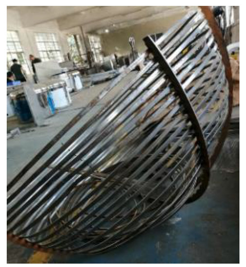
Figure 9.
Error in processing.
After the spherical frame is manufactured, in order to install the photovoltaic cells between the adjacent small iron bars, a two-component acrylic fast curing structural adhesive is used to bond the photovoltaic cells and the spherical frame. This adhesive can be used to bond the metal iron spherical frame with the glass material photovoltaic cells, and quickly cure to achieve a high bonding strength. The high-temperature resistance of the adhesive is also very important for the application of the powersphere. During the bonding process, the thickness of the adhesive was also adjusted to fine-tune the installation of the photovoltaic cells. The manufacturing results are shown in Figure 10.
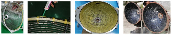
Figure 10.
The installation of the photovoltaic cell.
5. Comparison Experiment
After the powersphere is manufactured, a comparison experiment between the powersphere and the traditional photovoltaic panel is carried out, as shown in Figure 11. In the experiment, an 808 nm semiconductor laser was used as the light source, the spot diameter was 2 mm, and the divergence angle was 0.1263 rad. In the experiment, a 5 W laser was used to irradiate the powersphere and the traditional photovoltaic panel.
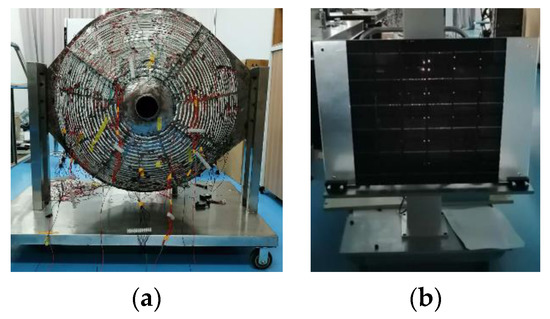
Figure 11.
Comparison experiment: (a) powersphere, (b) photovoltaic panel.
Since the powersphere has more than 7000 photovoltaic cells, the power ball is divided into 8 areas in the experiment, as shown in Figure 12. Ten photovoltaic cells in each area are connected in series to form a group. The maximum output voltage of each group is 5 V. Ten groups are connected in parallel to form a branch, and ten branches are connected in parallel to form an output terminal. That is, there are about 1000 photovoltaic cells in each area. In the experiment, the output current, voltage, and power of the powersphere under 5 W laser irradiation are 20.4 mA, 1.77 V, and 36.11 mW respectively, so its conversion efficiency is 0.72%.
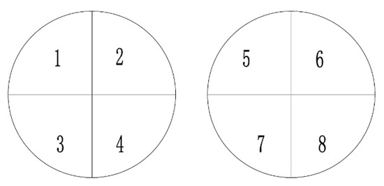
Figure 12.
The area distribution map of the powersphere.
In order to better understand the relationship between the conversion efficiency of a single photovoltaic cell and the conversion efficiency of the powersphere, the voltage and current values of the 20 × 20 mm photovoltaic cell under different powers are measured, as shown in Table 1.

Table 1.
The conversion efficiency of a single photovoltaic cell.
Since the area of the photovoltaic cell is 0.004 m2, when the laser power is 0.4 W, its illuminance is 1000 W/m2. This value is the standard illumination value for measuring the conversion efficiency of photovoltaic cells. Therefore, it can be seen from Table 1 that the conversion efficiency of a single photovoltaic cell is 35.85%, and with the increase of laser power, the conversion efficiency decreases slowly. When the laser power is 5 W, the conversion efficiency is only 2.25%. The main reason is that when the high-power laser irradiates the photovoltaic cell, the temperature of the photovoltaic cell will increase, thereby reducing the conversion efficiency. When the high-power laser irradiates the photovoltaic cell, it reaches light saturation, and a large number of lasers are reflected out. Therefore, for a single photovoltaic cell, it is not that the larger the irradiated laser power, the better.
The data in Table 1 show that a single photovoltaic cell usually has an output voltage of about 0.5 V and an output current of about 200 mA, which is far from enough for equipment. This requires multiple photovoltaic cells in series or parallel to improve the output power, such as the powersphere. However, it can be seen from the experimental results that under laser irradiation, the conversion efficiency of multi-photovoltaic cells is much lower than that of single photovoltaic cells. The main reason is that the output voltage or current of each photovoltaic cell is different under non-uniform Gaussian laser irradiation. For the series circuit, the output current of the multi-photovoltaic cells is usually the smallest output current of all photovoltaic cells, and the rest of the current is converted into heat and consumed. Similarly, the output voltage of the parallel circuit is the minimum output voltage of all photovoltaic cells. It is necessary to further improve the uniformity of light through optical methods or increase the output power of the circuit through electrical methods in subsequent research.
In order to understand the laser distribution on the inner surface of the powersphere, the output voltage and current of 8 areas were measured respectively, and the experimental data are shown in Table 2.
Table 2.
Current and voltage of the powersphere.
In Table 2, the maximum voltage of the 8 areas is 2.42 V, 5 voltages are 1.49–1.78 V, 2 voltages are below 1.49 V, and the minimum voltage is 1.27 V. The ratio of the minimum voltage to the maximum voltage is 52.48%. Compared with the voltage, the current is more affected by the non-uniformity of light. The maximum current in Table 2 is 8.38 mA, the minimum current is 1.00 mA, and the ratio of the minimum current to the maximum current is 11.93%. There are 5 currents that are 1–2 mA, the ratio of the minimum to maximum value in this range is 57.14%, and 2 currents are 2–2.5 mA and the ratio of the minimum to maximum value in this range is 88.56%. Except for the maximum current, the difference of other currents is only about 1 mA.
As can be seen from Table 2, the voltage and current of Area 2 are significantly greater than those of other areas. The main reason is that this area is directly irradiated by the laser, and this area can get the strongest laser irradiation. After the incident laser light is absorbed by the photovoltaic cell in Area 2, the laser energy is reduced by a considerable amount, which is close to 30%. As the number of absorption increases, the energy will decrease to zero eventually, so the number of reflections in the powersphere is limited. As a result, the illuminance of the inner surface of the powersphere cannot be equal through integration in the theoretical derivation, which affects the light uniformity effect of the powersphere. This needs to be further solved in following research from the absorption rate of the photovoltaic cell and increasing the optical system.
In addition, the data in Table 2 show that the circuits from Area 1 to Area 8 can output power. This shows that the photovoltaic cell in the opposite direction of laser transmission can obtain laser by reflection. That is, the powersphere can trap and reuse the laser reflected by the photovoltaic panel.
In the experiment, 36 pieces of 70 × 70 mm photovoltaic cells are used to form a 6 × 6 square flat photovoltaic, as shown in Figure 11b, and the maximum output voltage of each photovoltaic cell is 4 V. Like the powersphere, a 5 W 808 nm laser is used as the light source to illuminate the photovoltaic panel. In the experiment, a 2–5 times variable beam expander is also used to collimate the output laser, as shown in Figure 13. The beam expander achieves the purpose of collimation by reducing the divergence angle of the laser and increasing the size of the laser spot. When the beam expansion ratio changes, the size of the spot on the photovoltaic panel also changes, and the position of the photovoltaic plate can be moved to achieve the purpose of aiming. In the experiment, the center of the photovoltaic panel is adjusted to the center of the light spot, and then based on their coincidence point, the three XYZ positions of the photovoltaic panel are adjusted to fill the photovoltaic plate with light.
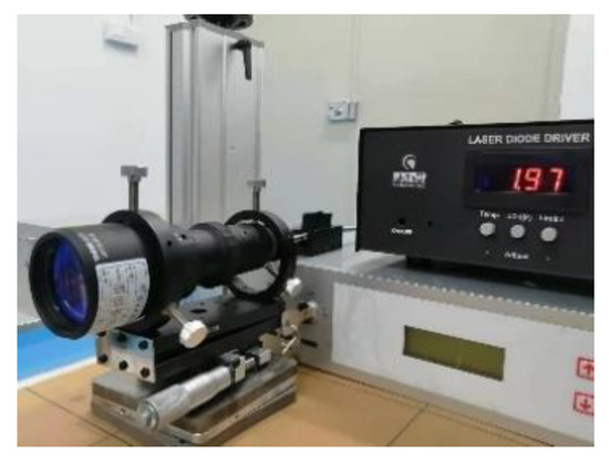
Figure 13.
Laser collimation mode.
The output voltage and current of 36 photovoltaic cells were measured when the beam expansion ratio was 2. The voltage value is shown in Table 3, and the current value is shown in Table 4.
Table 3.
Voltage of the photovoltaic panels.
Table 4.
Current of the photovoltaic panels.
There are two maximum values in Table 3, both are 4.37 V, and one minimum which is 2.21 V. The ratio of the minimum value to the maximum value is 50.57%. Fourteen voltages are 2–3 V, all located at the edge of the photovoltaic panel, which is the edge of the light spot, 10 voltages are 3–4 V, located in the middle or edge of the photovoltaic panel, and 11 voltages are 4–4.37 V, basically in the center of the light spot and the center of the photovoltaic panel position.
In Table 4, the maximum current is 31.05 mA, the minimum current is 0.10 mA, and the ratio of the minimum current to the maximum current is 0.32%. Nineteen currents are less than 1 mA, and the ratio of the minimum to maximum current in this range is 13.15%. Eight currents are 1–10 mA, the ratio of the minimum to maximum current in this range is 25.75%, five currents are 10–20 mA, and four currents are more than 20 mA.
When the beam expansion ratio increased to 4, the output voltage and current of 36 photovoltaic cells were also measured. The voltage value is shown in Table 5, and the current value is shown in Table 6.
Table 5.
Voltage of the photovoltaic panels under 4 times beam expansion.
Table 6.
Current of the photovoltaic panels under 4 times beam expansion.
There are also two maximum values of 4.27 V in Table 5, which is slightly lower than the maximum value of 4.37 V in Table 3, but the position of the maximum value remains unchanged. The minimum voltage in Table 5 is 2.5 V, which is higher than the minimum voltage of 2.21 V in Table 3, and its position has changed from the first row of the first column to the sixth row of the first column. The ratio of the minimum value to the maximum value is 58.54%, which is higher than that in Table 3. Two voltages are 2–3 V, less than Table 3, all located in the first column of the photovoltaic panel, which is the edge of the light spot. Sixteen voltages are 3–4 V, more than Table 3, located on the edge of the photovoltaic panel, and eighteen voltages are 4–4.27 V, in the center of the photovoltaic panel position.
By comparing with Table 3, it can be seen that the voltage at the center position in Table 5 decreases, the voltages at other positions increase, the number of maximum and minimum voltages decreases, and the number of intermediate voltages increases, indicating that the light obtained by each photovoltaic cell is more uniform. The main reason is that the beam expansion ratio increases, and the spot size becomes larger, so that the central light intensity of the spot becomes smaller, and the light intensity at other positions becomes smaller and expands outward. In short, the Gaussian distribution of the laser is not so obvious.
In Table 6, the maximum current is 18.2 mA, which is slightly lower than the maximum value of 31.05 mA in Table 4. The minimum current is 0.14 mA, which is higher than the minimum voltage of 0.10 mA in Table 4, and their position has changed from the first row of the first column to the sixth row of the first column. The ratio of the minimum current to the maximum current is 0.76%, which is higher than that in Table 4, 2 currents are less than 1 mA, less than Table 4, 26 currents are 1–10 mA, more than Table 4, and 8 currents are 10–20 mA.
Similar to the voltage, the beam expansion ratio increases, the maximum current becomes smaller, and the minimum current becomes larger. The number of extremely small currents is significantly reduced, and the number of intermediate values increases. The reason is that the beam expansion ratio becomes larger, the light spot becomes larger, the middle light intensity becomes smaller, and the edge light intensity becomes larger, so that the light intensity distribution is smoother.
Like Table 2, some areas in Table 3, Table 4, Table 5 and Table 6 also have significantly higher voltages and currents than other areas. But the reason for its generation is different from the powersphere, which mainly lies in Gaussian distribution of the laser irradiating it. The intensity of the laser is strong in the middle and weak at the edge, so that the voltage and current in the center of the spot are strong and the voltage and current in the edge region are weak.
According to the above current data of Table 4 and Table 6, we drew the shape of the light spot in matlab, as shown in Figure 14. Figure 14a is the original data graph under 2 times beam expansion, and Figure 14b is the interpolation graph under 2 times beam expansion, Figure 14c is the original data graph under 4 times beam expansion, and Figure 14d is the interpolation graph under 4 times beam expansion. It can be seen from Figure 14 that the light intensity distribution on the photovoltaic panel is high in the middle and low at the edge, which is a standard laser Gaussian distribution. However, the light intensity at the center of Figure 14a, b is stronger and the light intensity at the edge is weaker, that is, the light is more uneven. The light intensity distribution of Figure 14c, d is smoother, that is, the light is more uniform. Therefore, by comparing the data of the powersphere and the photovoltaic panel, the light uniformity effect of the powersphere can be evaluated. The comparative data is shown in Table 7. The first column in the table is the comparison of the minimum and maximum voltages ratios of the two receivers, where the photovoltaic panel contains two beam expansion ratios. The ratio of photovoltaic panels under 2 times beam expansion is the smallest, the ratio of powersphere is the second, and the ratio of photovoltaic panels under 4 times beam expansion is the largest. But the three ratios of voltage are all around 50%. Taking into account the error of the measured data, the difference of the ratio is not too big, indicating that the uniformity of light has less influence on the output voltage. The second column in Table 7 is the comparison of the minimum and maximum currents’ ratios of the two receivers. The ratio is only 0.32% in the photovoltaic panel under 2 times beam expansion, and even if the beam expansion ratio increases to 4, the ratio is only 0.76. The ratio of powersphere is 11.93%, which is 2 orders of magnitude higher than that of the photovoltaic panel. The ratio of the powersphere is obviously greater than the ratio of the photovoltaic panel, that is, the use of the powersphere can improve the uniformity of light and reduce the gap between the output currents of different branches. The experimental results show that the processed powersphere is consistent with the theoretical derivation and the design and has the effect of uniformizing the incident light.
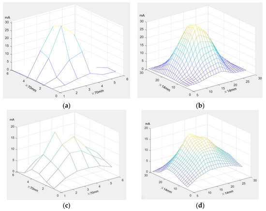
Figure 14.
The energy distribution diagram of light spot on photovoltaic panel. (a) The original graph under 2 times beam expansion, (b) the interpolation graph under 2 times beam expansion, (c) the original graph under 4 times beam expansion, and (d) the interpolation graph under 4 times beam expansion.
Table 7.
Voltage and current ration.
6. Conclusions
The powersphere is made up of many photovoltaic cells to form a spherical structure, which has a large external size and is difficult to process. To provide theoretical guidance for the design, manufacture, and application of the powersphere, the illuminance value of any position on the inner wall of the powersphere was theoretically deduced to be equal, and the calculation formula of this value was obtained. Using this theory, the structure of the powersphere was designed. The primary results are as follows: the diameter of the incident hole of the powersphere is 100 mm, the diameter of the powersphere is 1000 mm, and the inner wall of the powersphere is spliced by more than 7000 photovoltaic cells with a dimension of 20 × 20 mm.
By analyzing the feasibility of different processing methods and the results of processing experiments, the structure of the powersphere was designed, and the welding processing method was selected. The ball frame of the powersphere was machined by welding. The ball frame of the powersphere was processed by this method, and the adjacent rings in the ball frame were used for the installation of photovoltaic cells, forming a closed cavity sphere with a diameter of 1000 mm, and the inner surface of the sphere is the photovoltaic cell-receiving surface. A comparative experiment of powersphere and photovoltaic panel was carried out with the powersphere. The experimental results show that the powersphere has the function of light uniformity and repeated use of laser. The output current gap of each branch of the powersphere has been significantly reduced. It shows that the designed and processed powersphere is consistent with the theoretical analysis.
Author Contributions
T.H. and G.P. proposed the idea and conceptualization and performed the experiment; L.Z. and F.X. performed scientific discussions and supervised the work; C.Y., C.C.C., M.W. and G.Z. helped with revision and organization of the paper; G.P. and M.W. also supported funding acquisition. All authors have read and agreed to the published version of the manuscript.
Funding
This research was funded by NSFC, grant number 61805156, the Zhejiang Province key R&D project, grant number 2021C01112.
Conflicts of Interest
The authors declare no conflict of interest.
References
- Jin, K.; Zhou, W. Wireless Laser Power Transmission: A Review of Recent Progress. IEEE Trans. Power Electron. 2018, 34, 3842–3859. [Google Scholar] [CrossRef]
- Zhang, M.C.; Wang, J.H.; Shi, Y.W. Review of the wireless power transmission technology. J. Chongqing Technol. Bus. Univ. 2009, 26, 485–488. [Google Scholar]
- Howell, J.T.; Oneill, M.; Fork, R. Advanced Receiver/Converter Experiments for Laser Wireless Power Transmission. In Proceedings of the Solar Power from Space (SPS04) and 5th Wireless Power Transmission (WPT5) Conference, SPS’04.567, Granada, Spain, 30 June–2 July 2004; p. 187. [Google Scholar]
- Dickinson, R.M. Wireless power transmission technology state of the art the first Bill Brown lecture. Acta Astronaut. 2003, 53, 561–570. [Google Scholar] [CrossRef]
- Dickey, J.O.; Bender, P.L.; Faller, J.E. Lunar laser ranging: A continuing legacy of the Apollo program. Science 1994, 265, 482–490. [Google Scholar] [CrossRef] [PubMed]
- Kawashima, N.; Takeda, K.; Matsuoka, H.; Yamamoto, M. Laser Energy Transmission for a Wireless Energy Supply to Robots. In Proceedings of the 22nd International Symposium on Automation and Robotics in Construction, Ferrara, Italy, 11–14 September 2005; pp. 373–380. [Google Scholar]
- Li, S.; Mi, C.C. Wireless Power Transfer for Electric Vehicle Applications. IEEE J. Emerg. Sel. Top. Power Electron. 2015, 3, 4–17. [Google Scholar]
- Xiaoguang, L.; Wenshen, H.; Xun, L.; Tong, G. Methods to improve efficiency of photovoltaic receiver for laser powered unmanned aerial vehicle. Laser Infrared 2016, 45, 306002. [Google Scholar] [CrossRef]
- Shen, J.; Cheng, K.; Bo, M.A.; Jia, Y. Application Method of Laser Power Transmission in Orbit. Spacecr. Eng. 2015, 24, 25–30. [Google Scholar]
- Jomen, R.; Tanaka, F.; Akiba, T.; Ikeda, M.; Kiryu, K.; Matsushita, M.; Maenaka, H.; Dai, P.; Lu, S.; Uchida, S. Conversion efficiencies of single-junction III-V solar cells based on InGaP, GaAs, InGaAsP, and InGaAs for laser wireless power transmission. Jpn. J. Appl. Phys. 2018, 57, 578S3. [Google Scholar] [CrossRef]
- Hyde, R.; Dixt, S.; Weisberg, A.; Rushford, M. Eyeglass: A Very Large Aperture Diffractive Space Telescope. Astron. Telesc. Instrum. 2002, 4849, 28–39. [Google Scholar]
- Qiao, L.; Yang, Y. Experimental research of laser wireless power transmission efficiency. Laser Technol. 2014, 38, 590–594. [Google Scholar]
- Ugur, O.; Herbert, W.F. Power Sphere: A novel photovoltaic cavity converter using low bandgap TPV cells for efficient conversion of high power laser beams to electricity. AIP Conf. Proc. 2011, 738, 142–152. [Google Scholar]
- Ugur, O. A Review of Photovoltaic Cavity Converter Optics and It’s Impact on Multi-Junction and Multi-Bandgap Systems; OSA: Washington, DC, USA, 2011; SRThB1. [Google Scholar]
- Carr, K.F. Integrating sphere theory and applications Part I: Integrating sphere theory and design. Surf. Coat. Int. 1997, 80, 380–385. [Google Scholar] [CrossRef]
- Prokhorov, A.V.; Sapritsky, V.I.; Mekhontsev, S.N. Modeling of Integrating Spheres for Photometric and Radiometric Applications; SPIE: Bellingham, WA, USA, 1996; pp. 118–125. [Google Scholar]
- Crowther, B.G. Computer modeling of integrating spheres. Appl. Opt. 1996, 35, 5880–5886. [Google Scholar] [CrossRef] [PubMed]
- Ying-Wei, H.E.; Ping, L.I.; Hou-Ping, W.U.; Cheng, L.I.; Xiong, L.M. Output irradiance uniformity of integrating sphere source. J. Appl. Opt. 2012, 33, 548–553. [Google Scholar]
- Carr, K.F. Integrating sphere theory and applications Part II: Integrating sphere applications. Surf. Coat. Int. 1997, 80, 485–490. [Google Scholar] [CrossRef]
- Su, C.Z.; Cao, G.H.; Xu, H.J. Relationship analysis of output illuminance of integrating sphere and incident beam geometry. Laser Infrared 2010, 40, 195–199. [Google Scholar]
- Tranchart, S.B.; Bachir, I.H.; Destombes, J. Sensitive trace gas detection with near-infrared laser diodes and an integrating sphere. Appl. Opt. 1996, 35, 7070–7074. [Google Scholar] [CrossRef]
- Wu, F.R.; Fang, S.Y.; Gao, P.; Ma, S.; Xiong, B.; Yan, D.P. Integral Spherical Laser Power Meter and Its Application, China. CN202010393809.0, 11 May 2020. [Google Scholar]


Publisher’s Note: MDPI stays neutral with regard to jurisdictional claims in published maps and institutional affiliations. |
© 2021 by the authors. Licensee MDPI, Basel, Switzerland. This article is an open access article distributed under the terms and conditions of the Creative Commons Attribution (CC BY) license (http://creativecommons.org/licenses/by/4.0/).