Article

Single Headlamp with Low- and High-Beam Light

1
Department of Electro-Optical Engineering, Minghsin University of Science & Technology, Hsinchu 30401, Taiwan
2
Electronic and Optoelectronic System Research Laboratories, Industrial Technology Research Institute, Hsinchu 31040, Taiwan
*
Author to whom correspondence should be addressed.
Photonics 2021, 8(2), 32; https://doi.org/10.3390/photonics8020032
Submission received: 23 December 2020 / Revised: 18 January 2021 / Accepted: 25 January 2021 / Published: 27 January 2021
(This article belongs to the Special Issue Photonics, Optics and Laser Technology)

Abstract

:
Generally, automobiles are typically equipped with separate headlamp lanterns for generating low- and high-beam light. Compared with separate headlamp lanterns, a single headlamp producing both low- and high-beam light can be more compact and have less mechanical complexity. The single headlamp structure has become a main emphasis of research that manufacturers will continue to focus great efforts on in the future. A novel design of a single headlamp generating both low- and high-beam light is proposed in this study. The proposed headlamp consists of a compound ellipsoidal reflector, a baffle plate, a condenser lens, and LED array devices generating low- and high-beam light. The compound ellipsoidal reflector comprises a primary ellipsoidal reflector for generating low-beam light and a secondary ellipsoidal reflector for generating high-beam light. Monte Carlo ray tracing simulations were performed to confirm the optical characteristics of the proposed design. A prototype of the proposed headlamp was also fabricated and assembled to verify the design’s effectiveness. The simulated and measured illuminance distributions of the low-beam and high-beam light had the desired light patterns. Moreover, all the simulated and measured illuminances of each point and line met the ECE R112 regulation for low-beam and high-beam light. The proposed headlamp in this study is feasible for the application of single headlamp generating both low- and high-beam light.

Graphical Abstract

1. Introduction

In the initial stage of development of the automobile industry, headlamps were primarily used to illuminate roads, and no requirement existed pertaining to long-range illumination or light beam shape. However, with the rapid development of light sources, automotive lighting technology and high-efficiency light sources have become highly integrated. Currently, the major objective of vehicle lighting is to improve the driver’s visual performance at night or in dark places. In the last two decades, incandescent and tungsten halogen bulbs have been used in vehicle lighting, and presently, high-intensity discharge (HID) bulbs are implanted into some products. Light-emitting diode (LED) lighting exhibits some favorable characteristics, such as long life, high reliability, resistance to vibrations and shocks, high environment friendliness, low power consumption, small size, and high feasibility for the optical design of light beam shape. Their continued improvement makes it realistic to project LEDs as a promising technology for vehicle lighting [1,2,3]. For vehicle lighting, a well-designed headlamp can enable drivers to guide the vehicle safely at night along roads of varying geometries and to identify pedestrians and obstacles. For designing the light beam shape, various beam-shaping strategies for LED lighting [4] and LED-based automotive headlamps [3] have been proposed.
Automobiles are generally equipped with separate headlamps for generating high- and low-beam light. High-beam light offers superior visibility when driving at night on a deserted stretch of road. However, this light is too bright and can cause night blindness in oncoming drivers. In this case, a low-beam light directed toward the road without blinding the drivers in the front should be used. The Economic Commission for Europe (ECE) R112 regulation has declared clear low- and high-beam lighting requirements as well as measurement methods for lighting areas and spill zone intensity [5]. According to the regulation, high-beam light should only be used to illuminate far-off distances where visibility is mostly low in the absence of streetlights, thereby enabling long-range illumination of the road surface. The shape requirements for low-beam light can prevent the glare impact caused on a driver by a car moving in the opposite direction; thus, accidents can be prevented. According to brightness of the illuminating area affecting the traffic information when driving, it must meet the regulations of spill zone intensity to illuminate the billboard road information. Therefore, the optical design of low-beam light is the most difficult aspect in automotive lighting. To achieve regulation requirements, three basic structures have been proposed for traditional low-beam headlamps that use tungsten halogen or HID sources: reflector optics, projector module, and lens optics. To meet the ECE R112 regulation, all headlamps should provide a low-beam cutoff line. However, the optical characteristics of white LEDs are highly different from those of tungsten halogen or HID sources. Moreover, the output power generated from a single LED is less than that generated by exiting light sources. Thus, multiple LEDs are required for designing an LED headlamp. The expected optical design of an LED headlamp that can obtain a regulated light pattern with high efficiency depends on the optical characteristics of the LEDs forming the headlamp. Several complicated LED headlamp lenses have been developed [6], such as a lens that can transform the emergent ray into a rectangular beam region [7]; a low-beam LED headlamp based on microlenses [8]; an automotive headlight system incorporating digital micromirror devices [9]; an optical system with an ellipsoidal reflector, a baffle, and a faceted reflector [10]; an LED design with four main components: a focal LED, asymmetric metallic plate, freeform surface, and condenser lens [11]; a low-beam headlamp designed with Oliker’s ellipses technology [12]. Projector-type headlamps are substantially brighter in a focal spot than reflector headlamps are and, thus, can provide maximum vision when driving at night. Moreover, projector-type headlamps are less likely to cause night blindness in oncoming drivers because they are directed toward the road rather than the eyes of the drivers. Depending on their design and commercial use, projector-type LED headlamps can offer considerable benefits in vehicle lighting.
Automobiles are typically equipped with separate headlamp lanterns for generating low- and high-beam light. These lanterns are mounted adjacent to each other in the front of the car. Compared with conventional separate headlamp lanterns, a single headlamp producing both low- and high-beam light can be more compact and have less mechanical complexity. Moreover, the reduction in the number of parts and degrees of freedom during a single headlamp’s assembly simplifies the alignment of different light functions relative to each other. To produce both low- and high-beam light by using a single headlamp with halogen or HID bulbs, a movable shield or light baffle has been integrated into a projector-type headlamp [13,14]. For low-beam light, the shield blocks a portion of the lamp output to achieve the desired cutoff line. For high-beam light, the shield is moved out of the way and the light is allowed to pass through to enable long-range illumination of the road surface. However, because the moving parts in the structure are controlled by an electromagnetic actuator or a piezotranslator, which gradually deteriorates with time and changes in the environment and temperature, they can cause device failure. The aforementioned problem is a serious issue in vehicle lighting. To address this issue, white LEDs can be used to develop a single headlamp generating both low- and high-beam light. Zhu used an LED array to develop a single headlamp generating both low- and high-beam light [7], where a second optical lens was used to concentrate the light generated from the LED array to form a beam region on the screen. Then, different blocks were illuminated by lighting up different LEDs in the LED array to realize low- and high-beam lighting simultaneously. However, the uniformity of multiple LEDs in a single lifespan and the complicated circuit configuration were the challenges faced in this design. A compact LED composed of two rows of LED chips was also used as an automotive headlamp light source combining low- and high-beam light [2]. The primary optics in the structure collected the emission of the two closely spaced chip rows and simultaneously separated the respective contributions. Then, the secondary optics, which were based on a faceted reflector, were used to shape and realize the low- and high-beam patterns. The structure of a projector-type LED headlamp can be used to obtain both low- and high-beam light from a single headlamp. The light emitted from the low-beam LED array is reflected by the ellipsoidal reflector and cut off by the vertically oriented light baffle. Then, a low-beam output with a bright or dark edge is transmitted through the lens to form the desired cutoff line. Moreover, the lower surface of the vertically oriented light baffle is designed to redirect the light emitted from the high-beam LED array through the lens. The additive light reflected from the lower surface of the vertically oriented light baffle is transmitted through the lens and forms a bright or dark edge lacking high-beam light [15]. In a previous study, a single headlamp producing both low- and high-beam light was achieved with the reflected light baffle in a projector-type headlamp by adopting a condenser lens with a specific second surface to spread the light and obtain a predetermined beam pattern [16]. However, the structure of this condenser lens is complex, and difficulties exist in its manufacturing process.
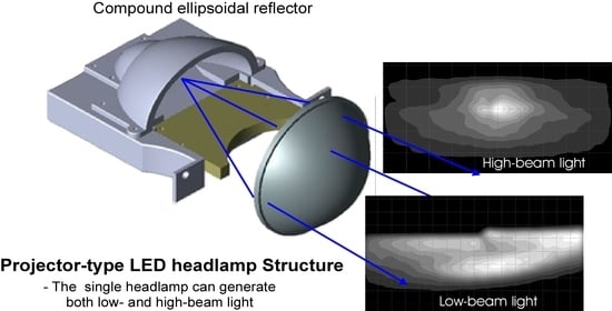
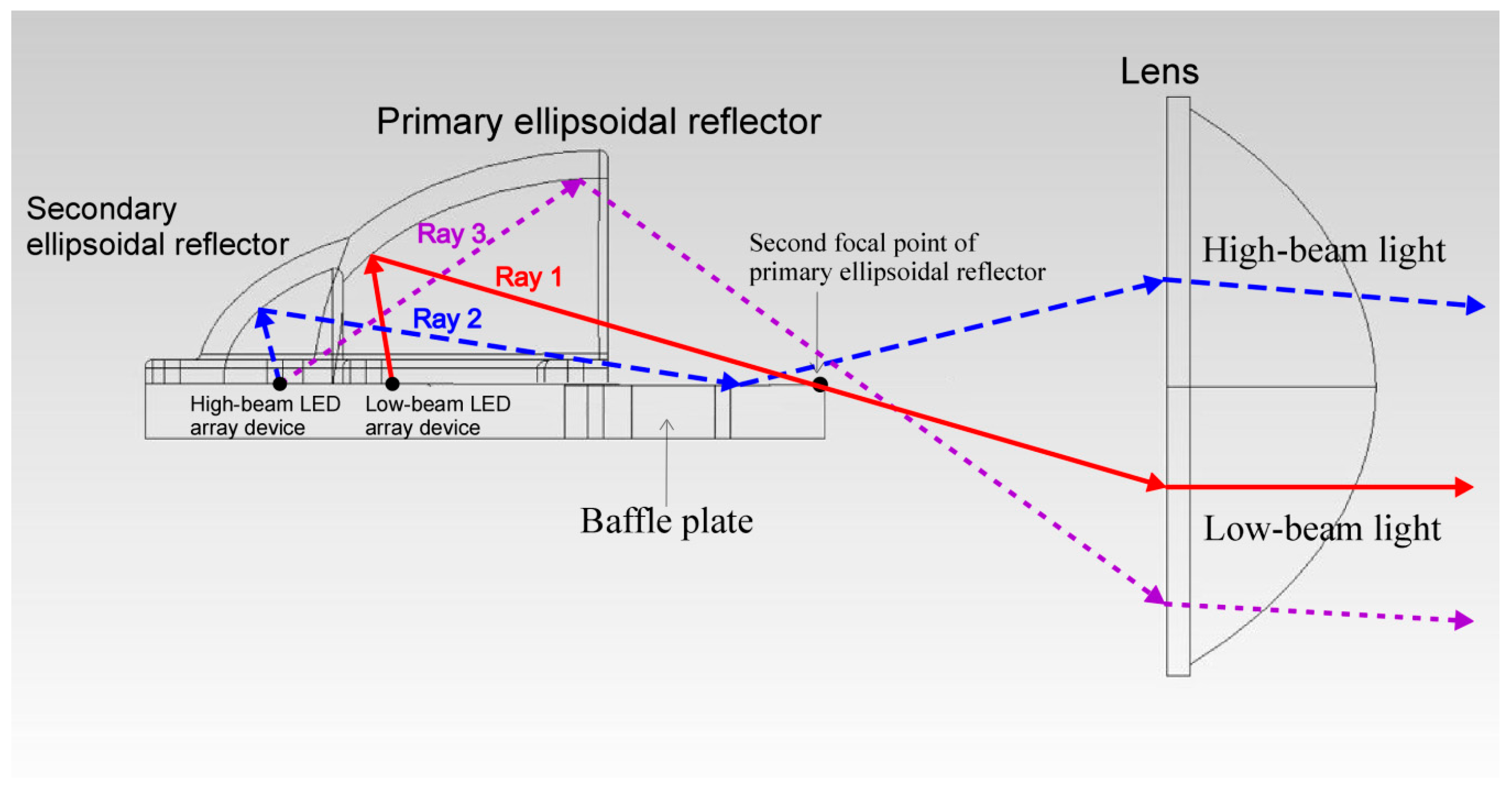
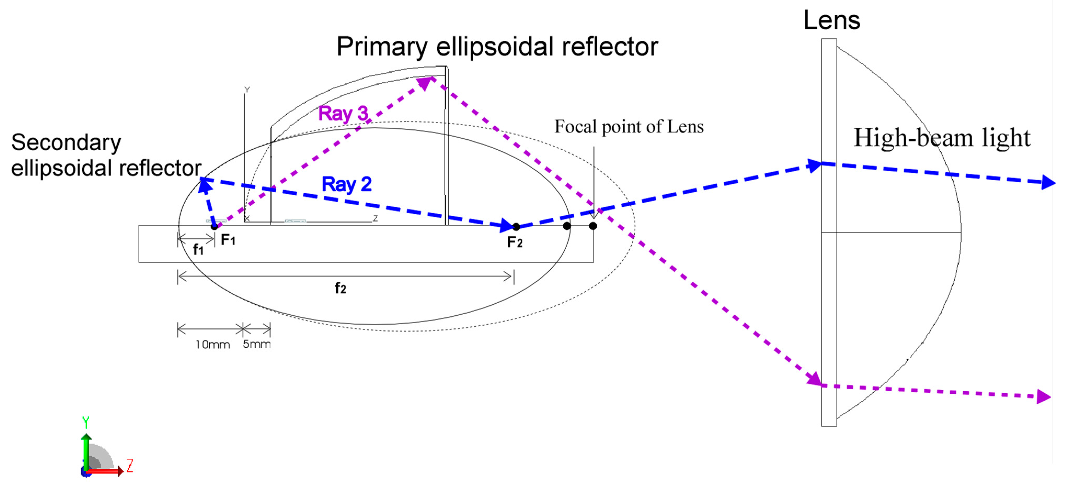
To address the aforementioned issues, the present paper proposes a novel LED headlamp design with a projector-type structure, in which both low- and high-beam light are generated using a single headlamp. As shown in Figure 1, the compound ellipsoidal reflector comprises a primary ellipsoidal reflector with a low-beam LED array device for generating low-beam light and a secondary ellipsoidal reflector with a high-beam LED array for generating high-beam light. The light emitted from the low-beam LED array device (ray 1) is reflected by the primary ellipsoidal reflector and cut off by the baffle. The low-beam output with a bright or dark edge is then transmitted through the lens to form a cutoff line for the low-beam light. Some of the light emitted from the high-beam LED array device (ray 2) is reflected by the secondary ellipsoidal reflector and the top surface of the baffle. This reflected light is then transmitted through the lens to illuminate the upper half region for generating high-beam light. In addition, some of the light emitted from the high-beam LED array device (ray 3) is reflected by the primary ellipsoidal reflector and then transmitted through the lens to illuminate the lower-half region for generating high-beam light. Thus, the illumination requirements of high-beam light can be achieved with the high-beam LED array device alone. The proposed compound ellipsoidal reflector design can be achieved using two simple ellipsoidal reflectors and a conventional condenser lens instead of a condenser lens with a complex surface. By using a projector-type structure with a specific condenser lens and baffle plate, the design of a single headlamp producing low- and high-beam light can meet the ECE R112 requirements.

2. Proposed Design Process and Simulation Results

A single projector-type headlamp generating both low- and high-beam light is expected to provide a low-beam cutoff line for low-beam light and bright, centrally distributed light with no particular control for high-beam light to meet the ECE R112 regulations. The proposed headlamp comprises a compound ellipsoidal reflector, a baffle, a condenser lens, and low- and high-beam LED array devices (Figure 1). For generating low-beam light, the LED light sources in the proposed headlamp are positioned at the first focal point (F1) of the ellipsoidal reflector. The light generated from the LED source converges to the second focal point (F2) after being reflected by the ellipsoidal reflector. Then, the projector lens with the overlapped second focal point of the ellipsoidal reflector projects the light from the ellipsoidal reflector at a certain distance. Thus, the designs of the compound ellipsoidal reflector and baffle plate as well as the choice of the condenser lens and LED array devices play crucial roles in the proposed headlamp structure.

2.1. Design of the Primary Ellipsoidal Reflector for Low-Beam Light

The ellipsoidal reflector for the LED projector-type headlamp is based on the basic principle of elliptical design. The elliptical equation can be expressed as follows:
x 2 a 2 + y 2 b 2 = 1
where 2a and 2b are the major and minor axes of the ellipse, respectively, and F1 and F2 are the first and second focal points of the ellipse, respectively. Figure 2 illustrates the defined first focal length (f1) and second focal length (f2) of the ellipse, which can be expressed as follows:
f 1 = a c
f 2 = a + c
where c is the linear eccentricity of the ellipse and can be expressed as follows:
c 2 = a 2 b 2
Considering the limited size of a modern headlamp, the major axis (a) of the primary ellipsoidal reflector of the proposed headlamp is set as 32–39 mm and f1 is set as 10 mm. From Equations (2)–(4), the values of b, c, and f2 can be calculated for the primary ellipsoidal reflector (Table 1). Figure 3 illustrates the corresponding ellipsoidal reflectors used in the proposed headlamp for generating low-beam light.
For generating low-beam light by using the proposed headlamp, the baffle plate is designed to hold the light emitted from the low-beam LED array device on the top surface of the plate and provide the required cutoff line by regulating the Z-shape prominent in front of the plate, as shown in Figure 4. To project the light from the Z-shaped prominent baffle at a distance, a projector lens with commercial specifications (diameter of 71 mm and focal length of 42 mm) is used. The material of the projector lens is selected as Schott BK7 glass. The reflectivity of the baffle plate and ellipsoidal reflector are assumed to be 0.9 [17]. An LED array device of OSLON Black Flat S (KW HJL531.TE, OSRAM Opto Semiconductors) is used to design the headlamp generating both low- and high-beam light. OSLON Black Flat S (KW HJL531.TE) is a three-chip LED device packed with three power chips (1 × 1 mm) on a ceramic board. By using the Rayfile of KW HJL531, the LED array device with an output power of 700 lm is positioned at F1 of the primary ellipsoidal reflector. To validate the effectiveness of the proposed design with different ellipsoidal reflectors, the commercial software TracePro for Monte Carlo ray tracing method is used for simulating the illuminance distribution in a detection plane placed 25 m in front of the low-beam LED headlamp.
Figure 5a displays the simulated illuminance distribution of the low-beam headlamp with primary ellipsoidal reflector No. 1, whose cutoff line meets the ECE R112 regulation. Figure 6 depicts the simulated illuminances of the low-beam headlamps with primary ellipsoidal reflector Nos. 1 to 5 at the test points on the detection plane. In Figure 6, the green lines represent the minimum required values at the test points according to the ECE R112 regulation, and the red lines represent the maximum required values. The illuminances at all the test points except certain ones, such as 75R, 50R, 50V, 25L, and 25R, cross the green lines, which indicates that most of the illuminances meet the ECE R112 requirement. Moreover, the illuminances of the 75L and 50L test points cross the red lines. Therefore, the illuminances at the bright center exceed the ECE R112 requirement, whereas those at the test points fail to meet the requirement. For the projector-type headlamps with symmetrical ellipsoidal reflectors, the projected light at the center of the detection plane is excessively high for the low-beam headlamp requirement. Moreover, the spill zone on the detection plane is excessively dark. An illuminance distribution with a wide horizontal spread on the detection plane can illuminate the broad light area and provide not only a suitable center light but also sufficient illuminance in the spill zone. To achieve a wide horizontal spread, the lateral expansion of a 2-mm-long ellipsoidal reflector can be used, as shown in Figure 7. For the lateral expansion of the primary ellipsoidal reflector, it is desired to concentrating more light emitting form the LED array device through the condenser lens to illuminate the region for low-beam light. Thus, the ellipsoidal reflector No. 1 with large size is chosen to be with a lateral expansion. Figure 5b displays the simulated illuminance distribution of the low-beam headlamp with laterally expanding ellipsoidal reflector No. 1. A wide horizontal spread on the detection plane can be achieved using the laterally expanding ellipsoidal reflector.

2.2. Design of the Secondary Ellipsoidal Reflector (ER) for High-Beam Light

To obtain a single headlamp with both low- and high-beam light, a compound ER composed of two simple ERs is used. The secondary ER concentrates the light generated by the high-beam LED array device onto its second focal point. By using a baffle plate and primary ER, the light generated from the high-beam LED array device can be directed and transmitted through a specific condenser lens to illuminate the region for high-beam light. The compound ER comprises a primary ER and secondary ER. The front part of the compound ER is the primary ER, which generates low-beam light, whereas the back part is the secondary ER, which generates high-beam light. For designing the compound reflector, the back part of the primary ER is removed and replaced by the secondary reflector, as shown in Figure 1. For the projector-type LED headlamp, some of the light emitted from the low-beam LED array device, which is reflected from the back part of the primary ER, contributes less to the illuminances at the test points and zone of the low-beam LED than the ECE requirement, as shown in Figure 8. Figure 9 illustrates the simulated illuminance distributions of this reflector with and without the back part, which are found to be similar. Although the illuminance without the back part is lower than that with it, all illuminances at the test points and zones of the primary ERs without the back part still meet the low-beam ECE requirement. Therefore, a 5-cm-long part is removed from the back of primary ER No. 1 and connected to the secondary ER. The depth of the hole made in this reflector is calculated to be 12.749 mm by using Equation (1).
In this study, the secondary ER concentrates the light emitted from the high-beam LED array device onto its second focal point. The light hitting this point is reflected by the baffle plate and directed through the lens to illuminate the region for high-beam light. However, the high-beam lighting should meet the ECE requirements. Thus, the light reflected by the baffle plate and directed through the lens should contribute to the illuminances at the specific points on the detection plane. According to the photometric requirements of high-beam light in the ECE R112 regulation, a light pattern with a large area should be formed. Therefore, the second focal point of the secondary ER for high-beam light should be away from the focal point of the lens, as shown in Figure 10. Consequently, the positions of the secondary ER and high-beam LED array device should be defined. Considering the size limitation of the compact headlamp, the length of the secondary ER should be less than 10 mm. Thus, the distance from the end of the secondary ER to that of the primary reflector is set as 10 mm. In other words, the distance from the end of the secondary ER to that of the primary reflector without the 5-cm-long back part is set as 15 mm. Moreover, the high-beam LED array device should be covered by the secondary ER to the maximum possible extent. The first focal length (f1) of the secondary ER should be small. Thus, this length is set as 5 mm, and the high-beam LED array is positioned at the first focal point of the secondary ER. After selecting the position and first focal length of the secondary ER, the second focal point of the secondary reflector can be defined according to its second focal length (f2). In addition, the distance between the second focal point of the secondary ER and the focal point of the lens is determined. To fit the height of the removed back part of the main second ER and due to the size limitation, the second focal length of the secondary ER is set as 57 mm.

3. Experimental Implementation and Discussion

In this study, Monte Carlo ray tracing simulations were performed to confirm the optical characteristics of the proposed novel design of a single headlamp generating both low- and high-beam light. A low-beam LED array device with a total output power of 700 lm was positioned at F1 of the primary ellipsoidal reflector, and a high-beam LED array device with a total output power of 1050 lm was positioned at F
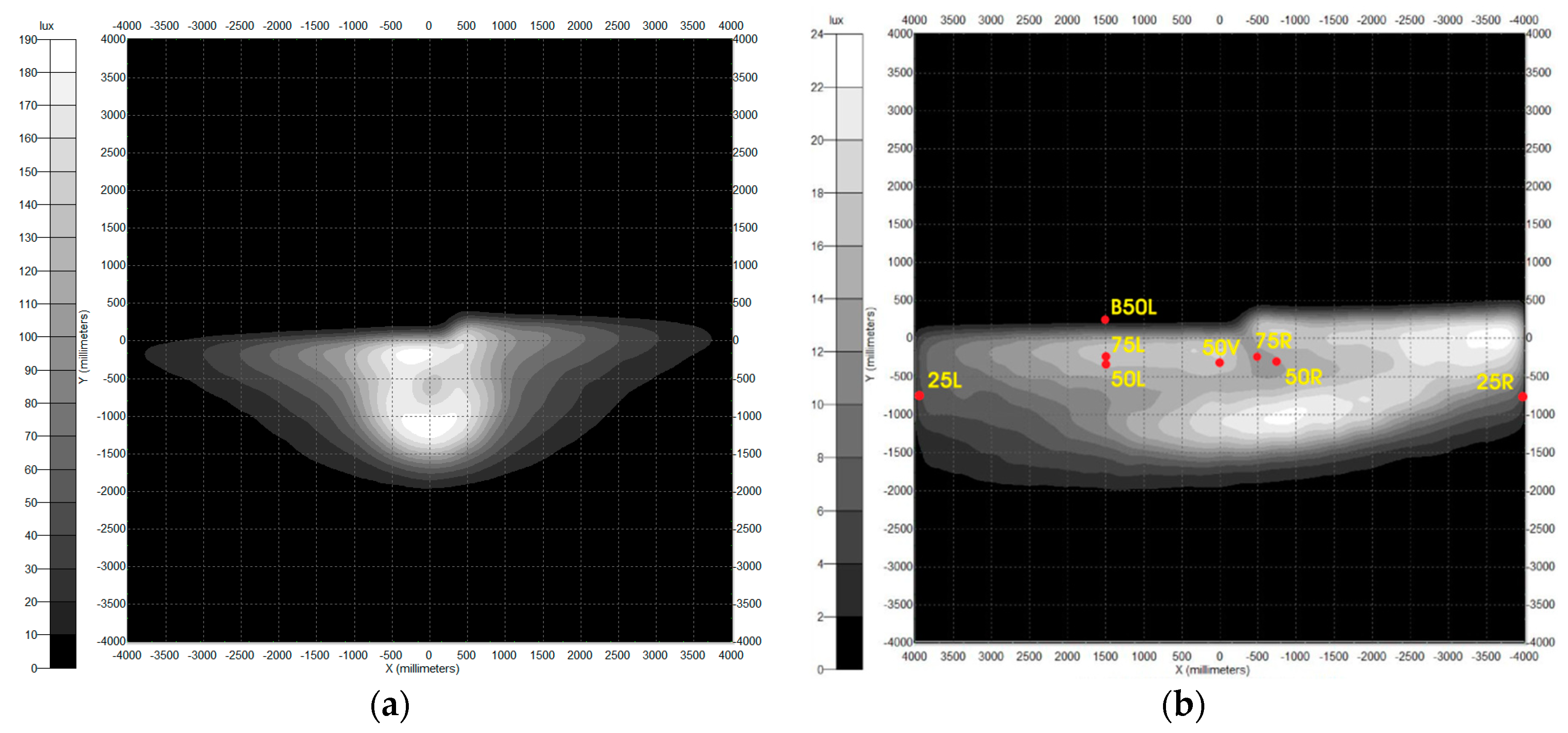
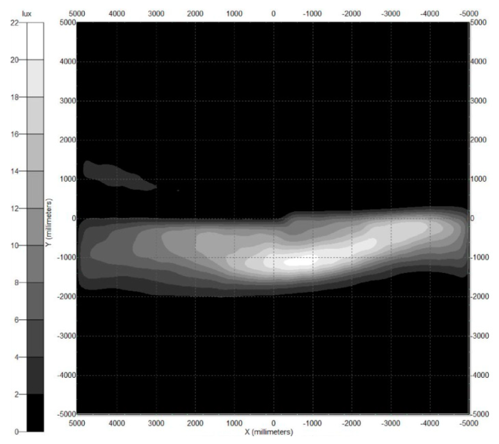
1 of the secondary ellipsoidal reflector. The target plane was placed 25 m from the lens. The simulated illuminance distribution of the low-beam light in the target plane is shown in 
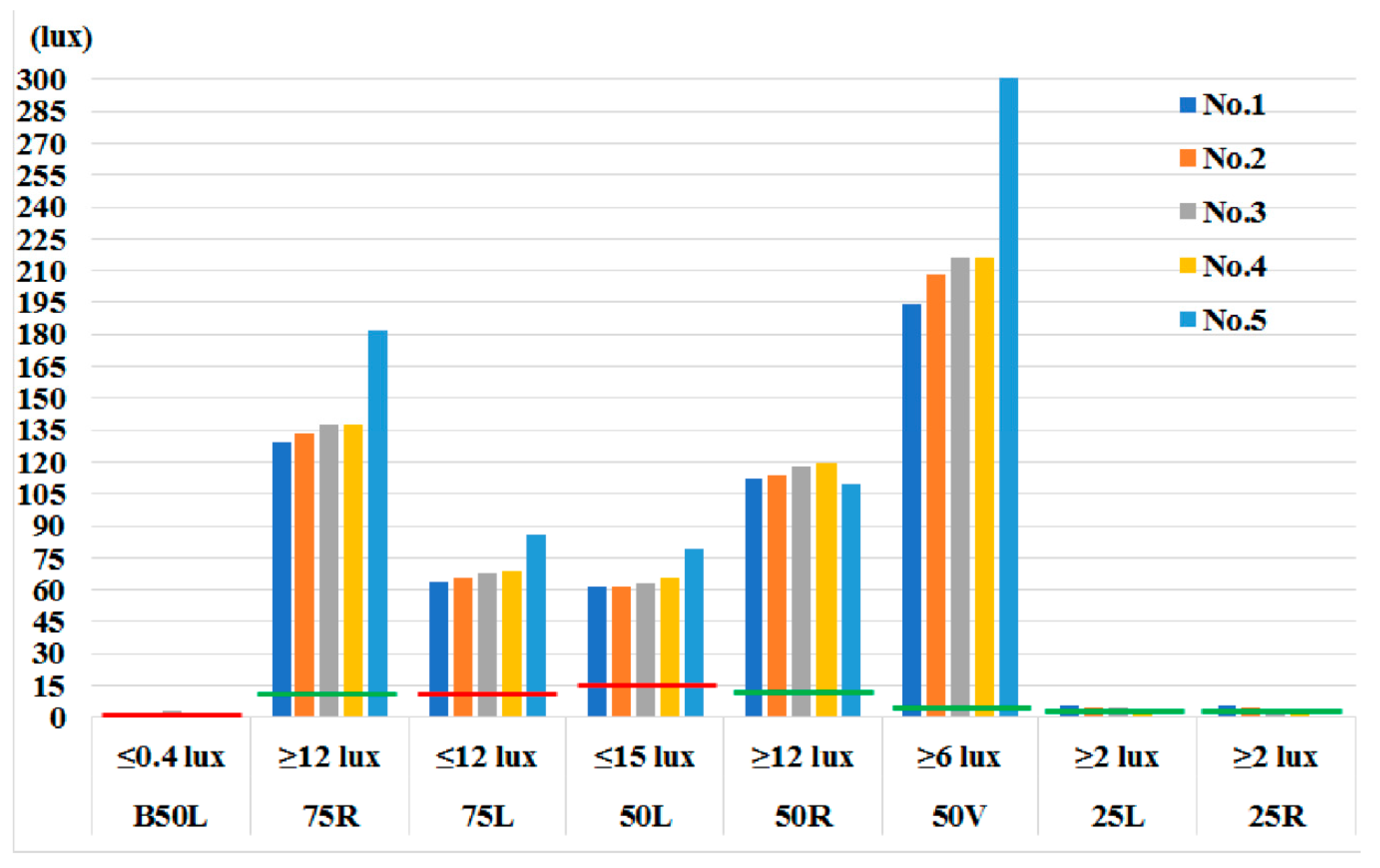
Figure 11, and the simulated and measured illuminances are listed in Table 2. The illuminance distribution of the low-beam light generated by the proposed headlamp with only the low-beam LED array device has a cutoff line meeting the ECE requirement. In addition, all illuminances of each point and line meet the ECE R112 regulation for low-beam light.
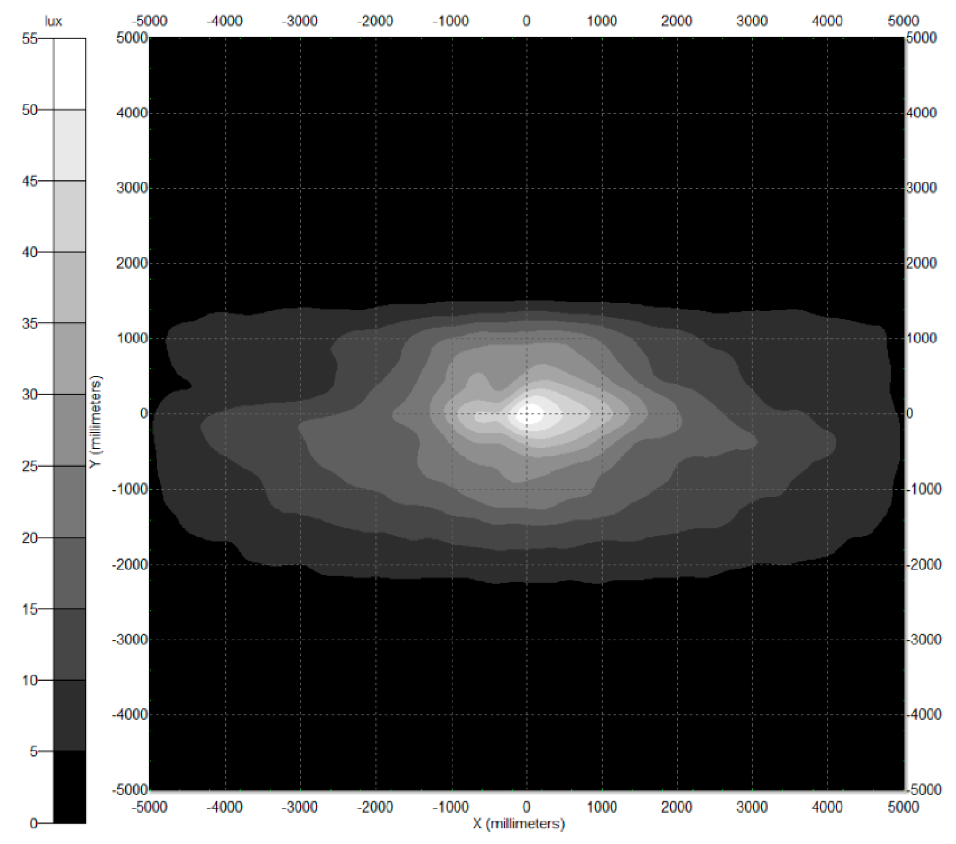
For the generation of high-beam light by using the proposed headlamp, a high-beam LED array device with a total output power of 1050 lm is positioned at F1 of the secondary ellipsoidal reflector. The simulated illuminance distribution of the low-beam light in the target plane is depicted in Figure 12, and the simulated and measured illuminances are listed in Table 3. The illuminance distribution of the high-beam light generated by the proposed headlamp with only the high-beam LED array device forms a light pattern with a large area, and all illuminances at each point and line meet the ECE R112 regulation for high-beam light.
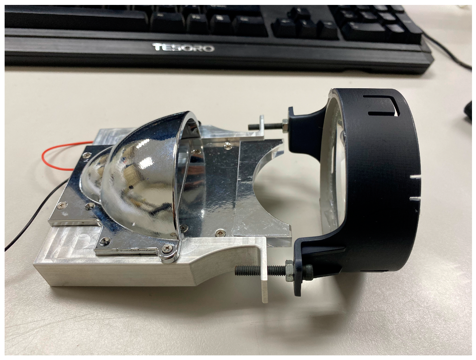
To verify the effectiveness of the proposed design, a prototype of the proposed headlamp was developed, as depicted in Figure 13. For the generation of low-beam light by using the proposed headlamp, the OSLON Black Flat S device (KW HJL531.TE, OSRAM Opto Semiconductors) was positioned at the first focal point of the primary ellipsoidal reflector and operated at 8.795 V and 0.5 A with an output of 700 lm. For generating high-beam light by using the proposed headlamp, the OSLON Black Flat S device was positioned at the first focal point of the secondary ellipsoidal reflector and operated at 9.339 V and 1.083 A with an output of 1050 lm. The luminous intensity distribution of the headlamp with only low- or high-beam light was measured using a goniophotometer (GMS-1800C; SENSING). The measurement results are listed in Table 2 and Table 3. All the illuminances of each point and line met the ECE R112 requirements for low- and high-beam light. However, the measured illuminances of each point and line in Table 2 and Table 3 are lower than the simulated ones. The reduction of the output powers of the low- and high-beam LED arrays owing to the heat is believed to be responsible for the lower measured illuminances of each point and line than the simulated ones.

4. Conclusions

This paper proposes a novel design of a single headlamp generating both low- and high-beam light to meet the ECE R112 regulation. The proposed headlamp adopts the structure of the projector-type headlamp and comprises a compound ellipsoidal reflector, a baffle plate, a condenser lens, and LED array devices generating low- and high-beam light. The compound ellipsoidal reflector comprises a primary ellipsoidal reflector for generating low-beam light and a secondary ellipsoidal reflector for generating high-beam light. The light emitted from the low- and high-beam LED array devices is reflected by the primary and secondary ellipsoidal reflectors, respectively, and transmitted through the condenser lens to illuminate the detection plane. Monte Carlo ray tracing simulations were performed to confirm the optical characteristics of the proposed design. The simulation results of the low-beam light with only the low-beam LED array device show that the proposed headlamp created a correct light pattern and performed an obvious cutoff line. All the simulated illuminances of each point met the ECE R112 regulation for low-beam light. Moreover, the simulation results of the high-beam light with only the high-beam LED array device formed a light pattern with a large area. In addition, all the simulated illuminances of each point and line met the ECE R112 regulation for high-beam light. A prototype of the proposed headlamp was also developed to verify the design’s effectiveness. By using the low-beam LED array device of merely 4.397 W, the measured illuminance distributions of the low-beam light can reach the illuminances of each point met the ECE R112 regulation for low-beam light. Additionally, the measured illuminance distributions of the high-beam light can reach the illuminances of each point and line met the ECE R112 regulation for high-beam light when the high-beam LED array device of merely 10.11 W was used. As a result, the proposed headlamp in this study is feasible for the application of single headlamp generating both low- and high-beam light.

Author Contributions

Conceptualization, S.-P.Y. and C.-Y.Y.; methodology, B.-M.C.; software, C.-Y.Y.; validation, S.-P.Y. and B.-M.C.; formal analysis, H.-K.F.; investigation, H.-K.F.; data curation, H.-K.F.; writing—original draft preparation, B.-M.C. All authors have read and agreed to the published version of the manuscript.

Funding

This research received no external funding.

Institutional Review Board Statement

Informed consent was obtained from all subjects involved in the study.

Conflicts of Interest

The authors declare no conflict of interest.

References

  1. Derlofske, J.F.V.; McColgan, M. White LED sources for vehicle forward lighting. SPIE Conf. Proc. 2002, 4776, 195–205. [Google Scholar]
  2. Brick, P.; Schmid, T. Automotive headlamp concepts with low-beam and high-beam out of a single LED. SPIE Conf. Proc. 2011, 8170, 817008. [Google Scholar]
  3. Long, X.; He, J.; Zhou, J.; Fang, L.; Zhou, X.; Ren, F.; Xu, T. A review on light-emitting diode based automotive headlamps. Renew. Sustain. Energy Rev. 2015, 41, 29–41. [Google Scholar] [CrossRef]
  4. Fournier, F.R. A review of beam shaping strategies for LED lighting. SPIE Conf. Proc. 2011, 8170, 817007. [Google Scholar]
  5. Economic Commission for Europe R112. Uniform provisions concerning the approval of motor vehicle headlamps emitting an asymmetrical passing-beam or a driving-beam or both and equipped with filament lamps and/or light-emitting diode (LED) modules. Off. J. Eur. Un. 2014. [Google Scholar]
  6. Chen, F.; Wang, K.; Qin, Z.; Wu, D.; Luo, X.; Liu, S. Design method of high-efficient LED headlamp lens. Opt. Express 2010, 18, 20926–20938. [Google Scholar] [CrossRef]
  7. Zhu, X.; Zhu, Q.; Wu, H.; Chen, C. Optical design of LED-based automotive headlamps. Opt. Laser Technol. 2013, 45, 262–266. [Google Scholar] [CrossRef]
  8. Wang, H.; Wang, X.; Li, Y.; Ge, P. Design of a newly projected light-emitting diode low-beam headlamp based on microlenses. Appl. Opt. 2015, 54, 1794–1801. [Google Scholar] [CrossRef]
  9. Hung, C.C.; Fang, Y.C.; Huang, M.S.; Hsueh, B.R.; Wang, S.F.; Wu, B.W.; Lai, W.C.; Chen, Y.L. Optical design of automotive headlight system incorporating digital micromirror device. Appl. Opt. 2010, 49, 4182–4187. [Google Scholar] [CrossRef]
  10. Ge, A.; Wang, W.; Du, Z.; Qiu, P.; Wang, J.; Cai, J. High-energy-efficiency optical system for an LED-based headlamp architecture. Appl. Opt. 2013, 52, 8318–8323. [Google Scholar] [CrossRef] [PubMed]
  11. Hsieh, C.C.; Li, Y.H.; Hung, C.C. Modular design of the LED vehicle projector headlamp system. Appl. Opt. 2013, 52, 5221–5229. [Google Scholar] [CrossRef] [PubMed]
  12. Chu, S.-C.; Chen, P.-Y.; Huang, C.-Y.; Chang, K.-C. Design of a high efficiency LED low-beam headlamp using Oliker’s compound ellipsoidal reflector. Appl. Opt. 2020, 59, 4872–4879. [Google Scholar] [CrossRef] [PubMed]
  13. Boroczki, A.; Horvath, C.; Panyik, T. Three-Mode Integrated Headlamp. U.S. Patent No. US20090251915A1, 8 October 2009. [Google Scholar]
  14. Huang, C.-Y. Controlling Device for a Headlamp High and Low Beam. U.S. Patent No. US8240889B2, 14 August 2012. [Google Scholar]
  15. Rice, L.M.; Tessnow, T. Headlamp Featuring Both Low-Beam and High-Beam Outputs and Devoid of Moving Parts. U.S. Patent No. US8894257B2, 25 November 2014. [Google Scholar]
  16. Chinniah, J.; Fallahi, A.P.; Sayers, E.M. LED Projector Headlamp Using Single or Multi-Faceted Lens. U.S. Patent No. US7563008B2, 21 July 2009. [Google Scholar]
  17. Ying, S.P.; Lyu, J.C. Ellipsoidal reflector design of the LED vehicle projector type headlamp. SPIE Conf. Proc. 2016, 9954, 99540P. [Google Scholar]
Figure 1. The structure of the single headlamp with low- and high-beam light in this study.
Photonics 08 00032 g001
Figure 2. Schematic of the ellipsoid.
Photonics 08 00032 g002
Figure 3. Schematic cross-sectional views of primary ellipsoidal reflector Nos. 1 to 5.
Photonics 08 00032 g003
Figure 4. The structure of the projector-type LED headlamp in this study.
Photonics 08 00032 g004
Figure 5. Simulated illuminance distributions of low-beam headlamps with the (a) symmetrical ellipsoidal reflector and (b) expanding ellipsoidal reflector.
Photonics 08 00032 g005
Figure 6. The simulated illuminances of the low-beam headlamps with primary ellipsoidal reflector Nos. 1 to 5 at the test points on the detection plane.
Photonics 08 00032 g006
Figure 7. The low-beam headlamp with laterally expanding ellipsoidal reflector No. 1.
Photonics 08 00032 g007
Figure 8. The structure of the projector-type LED headlamp in this study. Some of the light reflected from the back part of primary ellipsoidal reflector contributes less to the illuminances for low-beam regulation requirement.
Photonics 08 00032 g008
Figure 9. Simulated illuminance distributions of the primary ER No. 1 (a) with and (b) without the back part.
Photonics 08 00032 g009
Figure 10. The design of the secondary ellipsoidal reflector in this study.
Photonics 08 00032 g010
Figure 11. Simulated illuminance distribution of the low-beam light generated by the proposed headlamp.
Photonics 08 00032 g011
Figure 12. Simulated illuminance distribution of the high-beam light generated by the proposed headlamp.
Photonics 08 00032 g012
Figure 13. Prototype sample of the proposed headlamp.
Photonics 08 00032 g013
Table 1. Parameters of the primary ellipsoidal reflectors used in this study.
a (mm)c (mm)b (mm)f1 (mm)f2 (mm)
NO.138.528.525.871067
NO.2372725.291064
NO.335.525.524.641061
NO.4342424.041058
NO.532.522.523.441055
Table 2. Comparison of the simulated and measured illuminances of the LED headlamp with the corresponding values set by the ECE R112 regulation (Class B) for low-beam light.
Point on Measuring ScreenRequired Illuminance in LuxSimulated Illuminance in LuxMeasured Illuminance in Lux
B50L≤0.40.080.19
75R≥1213.7013.34
75L≤1210.669.66
50L≤1513.6112.86
50R≥1214.5913.26
50V≥614.2513.92
25L≥212.5112.19
25R≥211.5211.35
zone Ⅰ≤2 E*OKOK
zone Ⅲ≤0.7OKOK
zone Ⅳ≥3OKOK
E* is the actually measured value in point 50R.
Table 3. Comparison of the simulated and measured illuminances of the novel single headlamp with the corresponding values set by ECE R112 for high-beam light.
Point on Measuring ScreenRequired Illuminance in LuxSimulated Illuminance in LuxMeasured Illuminance in Lux
Emax≥48 & ≤24052.1851.75
Point HV≥0.8Emax41.7439.36
Point HV to 1125L and R≥2430.6928.65
Point HV to 2250L and R≥617.4715.6
Publisher’s Note: MDPI stays neutral with regard to jurisdictional claims in published maps and institutional affiliations.

