Abstract
The field of optical pulse-shaping and its applications is introduced, with a focus on time-domain approaches. A numerical investigation of all-fiber, time-domain, phase-only filtering is conducted for arbitrary temporal pulse synthesis. The theoretical phase modulation function required for generating use- specific target-intensity profiles is calculated using different optimization methods including a Brute Force Monte Carlo search, the Simulated Annealing method and the Genetic Algorithm method. The convergence speed, computational complexity and accuracy of these methods is compared under binary phase-only modulation, where the Genetic algorithm was found to outperform other methods.
1. Introduction
Optical pulse-shaping has attracted considerable interest in the last decade, due to its promise in a wide variety of applications, ranging from spectroscopy [1] to ultra-high bit rate optical communications [2]. From an applications perspective, pulse-shapers can be operated under either open-loop control or feedback (adaptive control) configurations, as shown in Figure 1a,b, respectively [3,4]. The open-loop configuration shown in Figure 1a can be used to generate user-specified target pulses [5] of particular interest. For example, in optical telecommunications, nearly square flat-top pulses found an application in optical switching and demultiplexing [6]. Moreover, the ability to generate periodic pulse patterns with a high frequency and nearly equal amplitude has found applications in ultra-high-speed optical communications [2,7]. Triangular pulses have the potential to be used as gating pulses in linear-frequency-resolved optical gating devices [8], and were found to enhance the performance of time-domain add-drop multiplexers [9]. Additionally, pulses with a parabolic intensity profile can propagate in a self-similar way [10] and are of great interest in laser wave-breaking operation [11]. Dark optical pulses were synthesized using optical pulse-shaping and used to demonstrate dark soliton propagation in optical fiber [12]. In addition to the aforementioned intensity profiles, optical pulse shaping was extensively used in optical code division multiple access (OCDMA) communications [13], where different users share a common optical fiber medium [14].

Figure 1.
Control schemes for optical pulse shaping. (a) Open loop control. (b) Feedback (adaptive control).
The adaptive feedback loop configuration of Figure 1b was used in the laser-assisted control of chemical or physical processes [4]. In essence, femto second pulses are used to influence the dynamics of a chemical or physical reaction, directing it towards a desired reaction or state [4]. This control process can be achieved through a learning loop consisting of a coherent laser source producing pulses in the femto- to peco-second timescale, a programmable pulse-shaper running an optimization algorithm and an experimental set-up, as shown in Figure 1b. A shaped laser pulse excites the sample, acting as a control signal, while a resulting probe pulse is sent to the optimization algorithm to adapt the control signal to steer the experiment to a desired state, even without any knowledge of the system’s Hamiltonian [4]. The learning loop shown in Figure 1b, was used to investigate the fluorescence excitation of dye molecules [15] and later found applications at the atomic level [16]. Furthermore, binary phase shaping was used to spectrally narrow multiphoton excitation using shaped laser pulses for two-photon microscopy [1]. In Ref. [1], experimental data are presented for ultra-short pulses of 10 fs duration using a learning loop similar to the one developed in [4,15]. This work will focus on the numerical investigation of programmable all-fiber time-domain phase-only filtering for the synthesis of arbitrary temporal pulses. The theoretical phase modulation function required for the generation of user-specific target-intensity profiles will be calculated using different optimization methods, including a Brute Force Monte Carlo search, Simulated Annealing method [5] and the Genetic Algorithm method [4]. The convergence speed and accuracy of these methods will be compared under binary phase-only modulation. The optimization methods compared in this work were recently adapted to control a programmable, mode-locked fiber laser [17].
2. Principle of Optical Pulse Shaping
Optical pulse shaping is based on linear time-invariant filtering. The process of linear filtering can be represented in the time domain through the impulse response function . The output of the pulse shaper eout(t) is characterized by the convolution of the input pulse ein(t) and h(t) as [3]:
here, * denotes convolution. Equation (1) shows, that for sufficiently short pulses, the process of generating a specific target waveform is equivalent to finding the appropriate impulse response. In the frequency domain, the output of linear filtering can be represented by [3]:
where , , and are the Fourier transforms of , and respectively. Pulse-shaping can naturally be understood through Equation (2). The input pulse is spread into its constituent spectral components through a diffraction grating, followed by a lens. A spatially modulated mask acts as a frequency domain transfer function, modifying both the phase and amplitude of the incident pulse, before a second lens and grating pair form the output pulse [5]. Essentially, the first and second grating and lens pairs perform forward and inverse Fourier transform, respectively.
3. Time Domain Pulse Processing
The process of pulse-shaping can be performed in terms of either frequency or time, as shown through Equations (1) and (2), respectively. The primary focus of this research article is on the time-domain pulse-shaping. A mathematical equivalence exists between the paraxial diffraction of light beams in space and the second-order temporal dispersion of optical pulses in fiber. This is known as the space–time duality principle, which enables the time-to-frequency conversion of optical pulses [18,19]. Temporal pulse shaping using time-domain filtering is equivalent to frequency domain pulse-shaping, as all-fiber temporal dispersion is used instead of spatial dispersion and an electro-optic (EO) modulator acts as a filter or mask. A block diagram of time-domain pulse-shaping is shown in Figure 2. Essentially, a second-order dispersive element with a high chromatic dispersion coefficient is used to temporally stretch the input pulse over a time window, hence mapping the amplitude spectrum to the time domain [20,21,22]. The EO phase modulator is then driven by a binary signal and acts as a phase-only filter over the stretched pulse. Finally, a second-order dispersive element with the opposite chromatic dispersion coefficient is used to compress the output pulse. Mathematically, the effect of the group velocity dispersion (GVD) experienced in both dispersive stages can be modeled as [23]:
where z is the length of the dispersive element, is the frequency axis, and are the output and input pulses of the dispersive element. The symbols and denote both forward and inverse Fourier transforms, respectively.
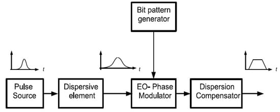
Figure 2.
Time-domain pulse-shaping block diagram [2,20,21].
It is worth noting that both the time and frequency domain approaches are equivalent, provided the proper choice of product is used in the dispersive element. The values for have to ensure that the ratio of the dispersed pulse width to the time domain phase modulation window is equivalent to the ratio of the pulse spectral width to the frequency domain phase modulation window. This ratio is dependent on the input pulse shape and spectrum, which would usually require a numerical estimation of . However, an analytical expression can be obtained, assuming chirp-free transform limited Gaussian input pulses:
where is the input pulse width, and are the time and frequency phase modulation windows, respectively. Furthermore, Equation (4) can be easily extended to chirped Gaussian pulses [23]. The results in Figure 3 show the equivalence of both approaches for ∼3.5 ps chirp-free transform-limit Gaussian input pulse phase, modulated using a binary phase function over a 1.6 ns time window, matching a frequency window of 0.4 THz. A 32-bit data sequence modulating the phase with this pattern: , where 0 and 1 correspond to and , respectively. The dispersed (stretched) and imposed phase modulation functions are shown in Figure 3a, while the output pulse intensity profiles for both the time and frequency approaches are shown in Figure 3b. The main disadvantage of the configuration shown in Figure 4 is the need for exact compensation in the pulse compression stage. This was overcome by utilize the same linearly chirped fiber Bragg grating (LC-FBG) from its two opposite ends, as the input and out of the dispersive element [20,21]. The experimental set-up used by [2] employs an active mode-locked fiber laser with a central wavelength nm to produce nearly transform-limited Gaussian pulses of ∼3.5 ps duration and a 10 GHz repetition rate, which was reduced to 625 MHz using a Mach–Zender amplitude modulator (MZM) and a bit pattern generator (BPG-1). The first dispersive stage is performed by propagating the pulses through a LC-FBG, incorporating a tunable mechanical rotator, permitting different values for the chromatic dispersion coefficient [20]. Setting the rotation angle to , a dispersion coefficient of 480 ps/nm is obtained over a 3 dB reflection bandwidth of 2.3 nm [20]. The temporally stretched pulses (exiting from port 3 of the circulator) are then routed through to the EO phase modulator (PM). The PM is driven by BPG-2, which generates a user-specific code at 20 Gb/s and a period of 1.6 ns [20]. Essentially, the 1.6 ns time-window is divided into 32 bins of 50 ps width, with each bin experiencing a or phase shift. Both BPG-1 and BPG-2 are synchronized through the same clock signal used in the active mode-locked laser. An optical delay line (ODL) is used to synchronize the phase code and the stretched pulse [20]. An exact dispersion compensation (−480 ps/nm) is achieved by propagating the pulses through the same LC-FBG. The output-shaped pulses are obtained form port 3 of the second circulator, discriminated using a polarization controller (PC) and a polarization beam splitter (PBS), and finally viewed on an optical spectrum analyzer (OSA) and an autocorrelator [20,21].
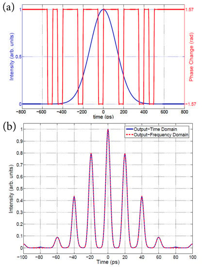
Figure 3.
Optical time-domain pulse-shaping. (a) Stretched Pulse and imposed phase modulation. (b) Output intensity for both time and frequency approaches.
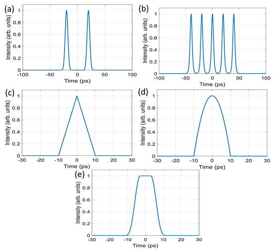
Figure 4.
Target pulse intensity profiles: (a) Two equal amplitude chirp-free 3.5 ps transform-limited Gaussian pulses separated by 20 ps, (b) Five equal amplitude chirp-free 2 ps transform-limited Gaussian pulses separated by 20 ps (inter-pulse amplitude fluctuations < ), (c) One 20 ps chirp-free triangular pulse intensity profile, (d) One 20 ps chirp-free parabolic pulse intensity profile, (e) One 20 ps chirp-free raised-cosine pulse, with a 10 ps flat-top region.
4. Phase-Only Optimization
It is known that, for a given input pulse spectrum and an output target-intensity profile, the complex frequency filter of both phase and amplitude can be found analytically, as shown by Equation (2). However, if the spectral amplitude is fixed, then a solution for the phase-only filter does not generally exist, unless the target intensity profile is, coincidentally, an outcome of phase-only filtering [24]. The design of the appropriate phase mask for frequency-domain pulse-shaping or phase modulation for time-domain pulse-shaping requires the use of optimization algorithms. These algorithms must be able to find the global optimum in a multidimensional parameter space. In this work, attention was paid to the Brute Force Monte Carlo method, the Simulated Annealing method [5] and Genetic Algorithm method [4,25].
4.1. Objective Function
The process of optimization involves finding the minimum or maximum of an objective function. For the purpose of pulse shaping the goal is to minimize the error between both target and output pulse intensity profiles. The objective function could be defined as the mean of the intensity difference between the target and the shaped pulse in the time domain [26], or the maximum deviation of the generated intensity from the target intensity over a specific time interval [5]. In this investigation, the latter approach is adapted and the global objective function is:
The objective function is evaluated over a equal to a time window of 1.6 ns, matching a frequency window of 0.4 THz. The objective function can be made to optimize specific features of the pulse [5]. For example, a large weight (penalty) could be assigned to minimize the deviation across the flat-top section of a raised-cosine target intensity. The input pulse assumed for all optimization algorithms is a ∼3.5 ps chirp-free transform-limit Gaussian pulse. To facilitate comparison between the optimization methods, different target intensity profiles were defined. Figure 4, contains time-domain traces of the target pulses intensities and their description int the caption. All target pulses were normalized to maintain the same input pulse energy before and after the pulse shaping process as phase-only filtering is assumed. The values for the weights in the objective function was set to unity, except for Figure 4e, were the 10 ps flat-top section was assigned a weight of 16. Consequently, the penalty of deviation from the target intensity profile is 16 times that of other portions of the pulse.
Numerically, the number of time samples assumed a value between – over the computational window of ps. Furthermore, binary phase-only modulation will be assumed throughout the following sections unless otherwise specified.
4.2. Brute Force Monte Carlo Method
Description
The key idea behind the Brute Force method is to attempt to find all possible target pulses resulting from all possible combinations of bits used in the phase-modulation process. Consequently, all possible values for are obtained and the minimum can easily be found. This approach may be feasible for problems with a small parameter space. However, its extremely high computational cost renders it impossible for use in larger problems. Following [20], and assuming a 32-bit word and a binary— or phase shifts, there are different possibilities. Furthermore, the symmetry of the target pulse does not necessarily impose a symmetry on the phase-modulation code. In fact, under a binary modulation of from 0 to , the output field satisfies and is always symmetric in time [5]. Consequently, the optimum code may be asymmetric and it is not sufficient to only explore possibilities.
Exploring all possible solutions would require ∼52 years running MATLAB on a 2.20 GHz processor. A possible solution to this problem is to use a Monte Carlo (MC) method instead of an exhaustive search. The MC technique can be defined as a simulation of a stochastic model, by which the expected value of certain random variables is related to a physical quantity that will be monitored [27,28]. MC simulations have been extensively employed in particle physics [28], heat transfer [29] and atmospheric optics [30]. In this study, the Brute Force MC method employs a uniform random number generator to select integers between 1 and . The number of integers is dependent on how long the simulation is designed to run. Each integer is then converted to its binary representation (1 and 0), which, in turn, is translated to a binary sequence of − or phase shifts.
4.3. Simulation Results
As an example, the Brute Force MC method was mployed to find the optimal code for generating an ultra-high-speed (∼50 GHz) periodic sequence of five pulses with nearly equalized amplitudes, as shown in Figure 4. The optimal phase modulation code is shown in Figure 5a, while the target and optimized temporal intensity profiles are shown in Figure 5b.
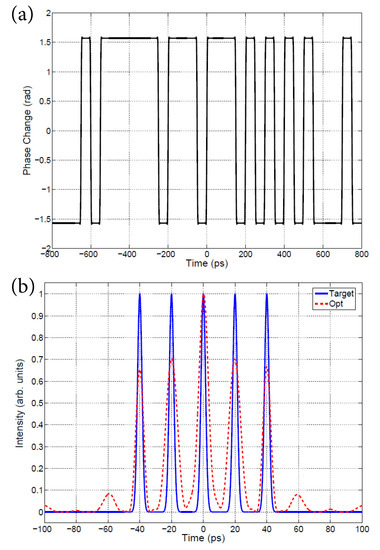
Figure 5.
Brute Force MC optimization. (a) Optimal phase modulation code. (b) Target and optimized temporal intensity profiles.
The minimum value of the objective function using this method was found to be using searchpoints. The number of searchpoints is an important parameter. The dependency of the objective function and computational time on the number of searchpoints is shown in Figure 6. As expected, the larger the number of searchpoints, the more likely it was that a minimum would be attained. However, there is no proof that any minima found through this method are in fact a global minima. However, the increase in the number of searchpoints reduces the variance in , as shown in Figure 6.
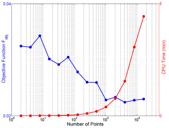
Figure 6.
The objective function and computational CPU time as a function of the number of points in the Brute Force MC method.
The Brute Force MC method could be improved by examining the target pulse. For example, optimization algorithms, implemented on square-like target pulses, produce code with large variations in the pulse spectral wings, where it is less sensitive to pulse-shaping [5], while optimizing the multiple pulses (similar to the example above) requires more variations around the pulse spectral center. This could be used to improve the focus of the random search employed in the Brute Force MC method, which can also employ a normal random search rather than a uniform search.
The following sections explore three optimization algorithms that exhibit a sense of direction when searching for the minimum, as opposed to the random search proposed here. Specifically, the Simulated Annealing method [5], and the Generic Algorithm method [4]. The two latter optimization algorithms fall in the category of global iterative search methods [31].
5. Simulated Annealing Method
5.1. Description
Simulated annealing (SA) method is a generic global optimization method that can be used to determine the global minima of an objective function over a large parameter space. The method was developed by Metropolis and co-workers [32,33,34]. The name of the method was inspired by annealing in metallurgy, where a material is heated and cooled in a controlled manner, allowing for an increase in the size of its crystals and a reduction in their defects. The SA method relies on the useful connection between statistical mechanics and combinatorial optimization. The former describes the behavior of systems with a high number of degrees of freedom at thermal equilibrium, while the latter relies on finding the minimum of a function with a large number of parameters [33,34].
As in physical process of annealing, each step of the SA method replaces the current system state by a random nearby state. The new neighbor state is chosen with a probability that depends on the difference between the corresponding objective function values and on a global control parameter T (called the temperature) that gradually decreases as the cooling process continues [33]. In essence, the amount of randomness in the system state is large for large T values and gradually decreases as T approaches zero. The simulation starts with an initial solution or system state defined as . In the context of pulse-shaping, the initial state of the system will be defined as a vector of pixels with each pixel assuming a value of either or . The minimum of the objective function is found by flipping the phase of one randomly selected pixel at a time [5]. A new state at iteration i is defined, and a is evaluated. The new solution is always accepted if . However, for , the change is accepted with a probability of , where represents the Boltzmann constant [5]. Effectively, a positive is occasionally accepted, allowing the algorithm to avoid local minimums. The cooling schedule (reduction in T) is lowered after a specified number of successful iterations ( is accepted) [5]. The convergence criteria are set when T approaches a specified minimum value or the number of failures ( is rejected) approaches a specified maximum value.
5.2. Simulation Results
As an example, the SA method was employed to find the optimal code for generating an ultra-high speed (∼50 GHz) periodic sequence of five pulses with nearly equalized amplitudes, as shown in Figure 4. The optimal phase modulation function and its binary form is shown in Figure 7a, while the target and optimized temporal intensity profiles are shown in Figure 7b. The minimum value of the objective function using this method was found to be .
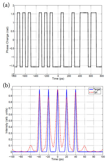
Figure 7.
Simulated Annealing method. (a) Optimal phase modulation code. (b) Target and optimized temporal intensity profiles.
The parameters used in the previous simulation were , ; the maximum number of successful iterations allowed per temperature was set as 100; the cooling schedule was set as ; the minimum temperature and the maximum number of consecutive failures allowed were 500.
The performance of the SA method shows a comparable performance to the Brute Force MC method at a lower computational cost. This could be attributed to the probabilistic and heuristic nature of the SA method [33]. It is worth noting that the SA method relies on the fundamental assumption that optimum solutions are more likely to be found in the neighborhood of already known optimum solutions, as opposed to randomly selecting from the entire solution space, as with the Brute Force MC method. However, in the previous SA implementation, the amount of change required to attain the optimum neighbor is limited to flipping one bit [5]. A more advantageous optimization method would be able to combine optimum solutions to obtain a new optimum solution; hence allowing for more change towards the global minimum. This is the main theme behind the evolutionary algorithms, which are discussed in the following section.
6. Genetic Algorithm Method
6.1. Description
Evolutionary algorithms emulate the process of natural selection, mutation and recombination [35]. The method description and notation closely follows the work presented in [4]. The simulation starts with a set of guesses or codes (vectors), which are selected based on random choice or an intelligent guess. The pool of initial vectors are called a population, and each vectortis called an individual, analogous to evolution in nature [4]. In this study, the number of individuals in the population P is kept constant throughout the simulation. Initially, the objective function is evaluated for each individual in the population and the vector resulting in the smallest value is the ‘fittest’ in an evolutionary sense. Subsequently, a deterministic selection rule is applied, by which the fittest m individuals are selected from within the population P to contribute to the generation of new offspring (new search points) [4,35]. The second step involves generating offsprings through recombination and mutation processes. The details of these processes can be found in [4,35] and are also described in [17].
6.2. Simulation Results
Following the simulation parameters in [4,17] and the physical system in [20], the population number was fixed to individuals, of which were selected to generate offspring. Each selected individual would produce six new offspring (two by recombination and four by mutation) [4]. The choice of recombination method was randomly chosen per parent. The new set of offsprings, 8 × 6, would replace the whole population as a seed to the next generation. The best-fit candidate was not moved to the subsequent generation, i.e., cloning was not adapted. The mutation probability was set to , and pixels were used per individual, with each pixel value being left unconstrained. The initial step length was set to , the contraction factor and cut-off threshold was . The optimization method would run until the worst individual was close enough to the best individual within a tolerance. The following simulations were performed while limiting the possible values per pixel to or to ensure only binary phase modulation.
As an example, the Genetic Algorithm (GA) method was employed to find the optimal code used in time-domain pulse-shaping to generate an ultra-high-speed (∼50 GHz) periodic sequence of five pulses with nearly equalized amplitudes, as shown in Figure 4. The evolution of the optimization algorithm is shown in Figure 8, with the worst, best and mean fitness values per generation. The optimal phase modulation function is shown in Figure 9a, while the target and optimized temporal intensity profiles are shown in Figure 9b. The minimum value of the objective function using this method was found to be after 100 generations.
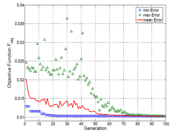
Figure 8.
Evolution of the Genetic Algorithm as a function of generations.
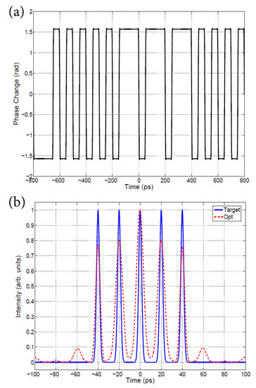
Figure 9.
Genetic Algorithm method. (a) Optimal binary phase modulation code. (b) Target and optimized temporal intensity profiles.
7. Comparison of Optimization Methods
Each optimization method introduced in the previous sections was tested with the different target intensity profiles shown in Figure 4. The optimization results for target pulses (a), (b), (c), (d) and (e) are tabulated in Table 1, Table 2, Table 3, Table 4 and Table 5, respectively. It is worth noting that the target intensity profile (b), shows the most variation between the optimization methods, and was thus the primary focus of the comparison. The remaining waveforms, namely (a), (c), (d), (e), result in similar outcomes. A representative example of the output waveform, obtained for (a) using Brute Force MC, (c) using Simulated Annealing and (d)/(e) using the Genetic algorithm, are reported in Figure 10.

Table 1.
Comparison of various phase-only optimization methods for the target intensity profile in Figure 6a.

Table 2.
Comparison of various phase-only optimization methods for the target intensity profile in Figure 6b.

Table 3.
Comparison of various phase-only optimization methods for the target intensity profile in Figure 6c.

Table 4.
Comparison of various phase-only optimization methods for the target intensity profile in Figure 6d.

Table 5.
Comparison of various phase-only optimization methods for the target intensity profile in Figure 6e.
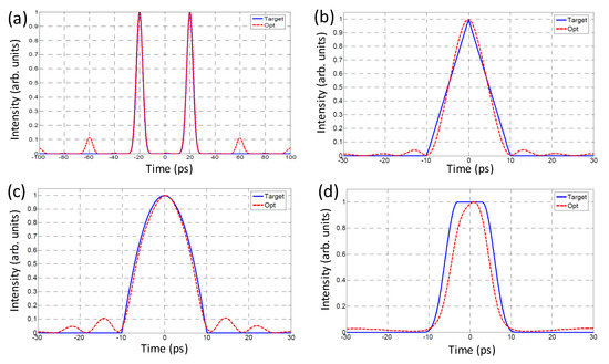
Figure 10.
A representative example of the optimized and target waveform obtained shown in Figure 4. (a) using Brute Force MC, (b) using Simulated Annealing, (c,d) using the Genetic Algorithm.
The Brute Force MC method was executed with searchpoints corresponding to ∼3 min CPU time (2.2 GHz processor). This is the same average time required to obtain a convergent solution using the GA method. The SA method used the same steering parameters that were presented earlier. The GA, on the other hand, stands out as the best candidate for binary phase-only pulse shaping. The computational cost associated with each method can be measured by the number of evaluations. The graph in Figure 11 shows the evolution of as a function of computational cost. The SA method outperforms the Brute Force MC method after a significant number of iterations, at which point the value of the objective function abruptly decreases to an acceptable level.

Figure 11.
Comparison of various phase-only optimization methods.
8. Conclusions
A numerical investigation of all fiber time-domain phase-only filtering for arbitrary temporal pulse synthesis was conducted. The theoretical phase modulation function required to generate user-specific target-intensity profiles wascalculated using different optimizations methods, including a Brute Force Monte Carlo search, the Iterative Fourier Transform method, the Simulated Annealing method and the Genetic Algorithm method. The convergence speed, computational complexity and accuracy of these methods was compared under binary phase-only modulation, where the Genetic algorithm was found to outperform other methods.
Author Contributions
Conceptualization, A.S.K.; methodology, A.S.K. & J.M.H.B.; software, A.S.K. & B.N.; validation, A.S.K. & D.C.; formal analysis, I.B. & B.N.; investigation, R.G. & D.C.; resources, Z.A.B. & A.S.K.; writing—original draft preparation, A.S.K. & R.G.; writing—review and editing, A.S.K. & Z.A.B.; supervision A.S.K. All authors have read and agreed to the published version of the manuscript.
Funding
This research received no external funding.
Institutional Review Board Statement
Not Applicable.
Informed Consent Statement
Not Applicable.
Data Availability Statement
Not Applicable.
Conflicts of Interest
The authors declare no conflict of interest.
References
- Comstock, M.; Lozovoy, V.V.; Pastirk, I.; Dantus, M. Multiphoton intrapulse interference 6; binary phase shaping. Opt. Express 2004, 12, 1061–1066. [Google Scholar] [CrossRef]
- Azaña, J.; Berger, N.; Levit, B.; Fischer, B. Reconfigurable generation of high-repetition-rate optical pulse sequences based on time-domain phase-only filtering. Opt. Lett. 2005, 30, 3228–3230. [Google Scholar] [CrossRef] [PubMed]
- Weiner, A.M. Femtosecond pulse shaping using spatial light modulator. Rev. Sci. Instrum. 2000, 71, 1929–1960. [Google Scholar] [CrossRef]
- Zeidler, D.; Frey, S.; Kompa, K.-L.; Motzkus, M. Evolutionary algorithms and their application to optimal control studies. Phys. Rev. A 2001, 64, 023420. [Google Scholar] [CrossRef]
- Weiner, A.M.; Oudin, S.; Leaird, D.E.; Reitze, D.H. Shaping of femtosecond pulses using phase-only filters designed by simulated annealing. J. Opt. Soc. Am. A 1993, 10, 1112–1120. [Google Scholar] [CrossRef]
- Slavik, R.; Oxenlowe, L.K.; Galili, M.; Mulvad, H.C.H.; Park, Y.; Azaña, J.; Jeppesen, P. Demultiplexing of 320-Gb/s OTDM data using ultrashort flat-top pulses. IEEE Photon. Technol. Lett. 2007, 19, 1855–1857. [Google Scholar] [CrossRef]
- Caraquitena, J.; Jiang, Z.; Leaird, D.E.; Weiner, A.M. Simultaneous repetition-rate multiplication and envelope control based on periodic phase-only and phase-mostly line-by-line pulse shaping. J. Opt. Soc. Am. B 2007, 24, 3034–3039. [Google Scholar] [CrossRef]
- Latkin, A.I.; Boscolo, S.; Turitsyn, S.K. Passive nonlinear pulse shaping in normally dispersive fiber. In Proceedings of the OFC/NFOEC 2008, San Diego, CA, USA, 24–28 February 2008. [Google Scholar]
- Parmigiani, F.; Petropoulos, P.; Ibsen, M.; Ng, T.T.; Richardson, D.J. OTDM add-drop multiplexer using a saw-tooth pulse shaper. In Proceedings of the 34th European Conference on Optical Communications (ECOC), Brussels, Belgium, 21–25 September 2008. [Google Scholar]
- Fermann, M.E.; Kruglov, V.I.; Thomsen, B.C.; Dudley, J.M.; Harvey, J.D. Self-similar propagation and amplification of parabolic pulses in optical fibers. Phys. Rev. Lett. 2000, 84, 6010–6013. [Google Scholar] [CrossRef]
- Ilday, F.O.; Buckley, J.R.; Clark, W.G.; Wise, F.W. Self-similar evolution of parabolic pulses in a laser. Phys. Rev. Lett. 2004, 92, 213902. [Google Scholar] [CrossRef]
- Weiner, A.M.; Heritage, J.P.; Hawkins, R.J.; Thurston, R.N.; Kirschner, E.M.; Leaird, D.E.; Tomlinson, W.J. Experimental observation of the fundamental dark soliton in optical fibers. Phys. Rev. Lett. 1988, 61, 2445–2448. [Google Scholar] [CrossRef]
- Wang, X.; Wada, N. Spectral phase encoding of ultra-short optical pulse in time domain for OCDMA application. Opt. Express 2007, 15, 7319–7326. [Google Scholar] [CrossRef][Green Version]
- Sardesai, H.P.; Chang, C.C.; Weiner, A.M. A femtosecond code-division multiple-access communication system test bed. J. Light. Technol. 1998, 16, 1953–1964. [Google Scholar] [CrossRef]
- Bardeen, C.J.; Yakovlev, V.V.; Wilson, K.R.; Carpenter, S.; Weber, P.M.; Warren, W.S. Feedback quantum control of molecular electronic population transfer. Chem. Phys. Lett. 1997, 280, 151–158. [Google Scholar] [CrossRef]
- Weinacht, T.C.; Ahn, J.; Bucksbaum, P.H. Controlling the shape of a quantum wavefunction. Nature 1999, 397, 233–235. [Google Scholar] [CrossRef]
- Karar, A.S.; Ghandour, R.; Mahariq, I.; Alboon, S.A.; Maaz, I.; Neji, B.; Barakat, J.M.H. A Programmable Mode-Locked Fiber Laser Using Phase-Only Pulse Shaping and the Genetic Algorithm. Photonics 2020, 7, 69. [Google Scholar] [CrossRef]
- Kolner, B.H. Space-time duality and the theory of temporal imaging. IEEE J. Quant. Electron. 1994, 30, 1951–1963. [Google Scholar] [CrossRef]
- Jannson, T. Real-time fourier transformation in dispersive optical fibers. Opt. Lett. 1983, 8, 232–234. [Google Scholar] [CrossRef]
- Thomas, S.; Malacarne, A.; Poti, L.; Bogoni, A.; Azaña, J. Programmable all-fibre optical pulse shaper based on time-domain binary phase-only linear filtering. In Proceedings of the European Conference on Optical Communications (ECOC), Brussels, Belgium, 21–25 September 2008. [Google Scholar]
- Thomas, S.; Malacarne, A.; Fresi, F.; Poti, L.; Azana, J. Fiber-Based Programmable Picosecond Optical Pulse Shaper. J. Light. Technol. 2010, 28, 1832–1843. [Google Scholar] [CrossRef]
- Saperstein, R.E.; Ali´c, N.; Panasenko, D.; Rokitski, R.; Fainman, Y. Timedomain waveform processing by chromatic dispersion for temporal shaping of optical pulses. J. Opt. Soc. Am. B 2005, 22, 2427–2436. [Google Scholar] [CrossRef]
- Agrawal, G.P. Nonlinear Fiber Optics; Academic Press: New York, NY, USA, 2001. [Google Scholar]
- Hacker, M.; Stobrawa, G.; Feurer, T. Iterative Fourier transform algorithm for phase-only pulse shaping. Opt. Express 2001, 9, 191–199. [Google Scholar] [CrossRef] [PubMed]
- Sheveleva, A.; Colman, P.; Finot, C. The temporal analogue of diffractive couplers. Results Opt. 2021, 3, 100059. [Google Scholar] [CrossRef]
- Rundquist, A.; Efimov, A.; Reitze, D.H. Pulse shaping with the Gerchberg-Saxton algorithm. J. Opt. Soc. Am. B 2002, 19, 2468–2478. [Google Scholar] [CrossRef]
- Binder, K.; Heermann, D.W. Monte Carlo Simulation in Statistical Physics; Springer: Berlin, Germany, 2002. [Google Scholar]
- Brandt, S. Data Analysis: Statistical and Computational Methods for Scientists and Engineers; Springer: New York, NY, USA, 1999. [Google Scholar]
- Xia, X.L.; Ren, D.P.; Tan, H.P. A curve Monte-Carlo method for radiative heat transfer in absorbing and scattering gradient-index medium. Numer. Heat Transf. Part Fundam. 2006, 50, 181–192. [Google Scholar] [CrossRef]
- Marshak, A.; Davis, A.B. 3D Radiative Transfer in Cloudy Atmospheres; Springer: Berlin, Germany, 2005. [Google Scholar]
- Belegundu, A.D.; Rupatla, T.R.C. Optimization Concepts and Applications in Engineering; Prentice-Hall: New Jersey, NJ, USA, 1999. [Google Scholar]
- Metropolis, N.; Rosenbluth, A.; Rosenbluth, M.; Teller, A.; Teller, E. Equations of state calculations by fast computing machines. J. Chem. Phys. 1953, 21, 1087–1092. [Google Scholar] [CrossRef]
- Kirkpatrick, S.; Gelatt, C.D.; Vecchi, M.P. Optimization by simulated annealing. Science 1983, 220, 671–680. [Google Scholar] [CrossRef]
- Cerny, V. A thermodynamical approach to the travelling salesman problem: An efficient simulation algorithm. J. Optm. Theor. Appl. 1985, 45, 41–51. [Google Scholar] [CrossRef]
- Goldberg, D.E. Genetic Algorithm in Search, Optimization and Machine Learning; Addison-Wesley: Reading, MA, USA, 1997. [Google Scholar]
Publisher’s Note: MDPI stays neutral with regard to jurisdictional claims in published maps and institutional affiliations. |
© 2021 by the authors. Licensee MDPI, Basel, Switzerland. This article is an open access article distributed under the terms and conditions of the Creative Commons Attribution (CC BY) license (https://creativecommons.org/licenses/by/4.0/).