Article

Generation of Subpicosecond Pulse Trains in Fiber Cascades Comprising a Cylindrical Waveguide with Propagating Refractive Index Wave

1
S.P. Kapitsa Scientific Technological Research Institute, Ulyanovsk State University, 42 Leo Tolstoy Street, 432970 Ulyanovsk, Russia
2
Prokhorov General Physics Institute of the Russian Academy of Sciences, 38 Vavilov Street, 119991 Moscow, Russia
3
Electromagnetism and Telecommunication Department, University of Mons, B-7000 Mons, Belgium
*
Author to whom correspondence should be addressed.
Photonics 2021, 8(11), 484; https://doi.org/10.3390/photonics8110484
Submission received: 18 September 2021 / Revised: 25 October 2021 / Accepted: 26 October 2021 / Published: 29 October 2021
(This article belongs to the Special Issue Specialty Optical Fibers, Fiber Lasers and Their Applications)

Abstract

:
A cylindrical waveguide structure with the running refractive index wave has been recently demonstrated as a means for the generation of high-repetition-rate pulse trains. The operation mechanism involves a proper combination of the frequency modulation and modulation instability simultaneously experienced by the input continuous wave (CW) signal as it propagates through the cylinder waveguide. Here, we explore the same idea but employ the cylindrical waveguide only as a part of the cascaded optical fiber configuration now comprising both passive and active optical fiber segments. The new system design enables the improved control of the pulse train formation process in the cascaded system elements, relaxes strong requirements for the CW signal power, and provides an additional optical gain for the advanced pulse peak power scaling. In particular, using a low-amplitude, weakly modulated, continuous wave as an input signal we explore and optimize the nonlinear mechanisms underlying its cascaded transformation into the train of kilowatt peak power picosecond pulses.

1. Introduction

Propagation of a light pulse in a waveguide with the running refractive index wave (RRIW) is accompanied by effects unavailable in the waveguide without RRIW [1,2]. In particular, the generation of soliton-like pulses through the modulation instability in such waveguides has been intensively studied [3,4]. In addition, the formation of azimuthal whispering gallery modes (AWGMs) in such waveguides has been a topic of a particular interest [5,6,7,8]. Specifically, the AWGM propagating along the surface of a cylindrical silica fiber follows a spiral trajectory with a certain even step. The typical longitudinal group velocity (along the waveguide axis) of spiral waves is commonly much less than the speed of light in vacuum [2,3,5]. However, it could be close to the speed of RRIW, leading to a pronounced resonance interaction between the AWGM and the RRIW, resulting in the formation of regular optical pulse trains.
This effect has been studied theoretically with a cylindrical waveguide structure comprising an RRIW [9,10]. The operation mechanism involves a proper combination of the frequency modulation and modulation instability (MI) that are simultaneously experienced by the input continuous wave signal as it propagates through the cylinder waveguide following the spiral trajectory. Importantly, the MI in the cylindrical waveguide with RRIW significantly differs from the MI observed in optical fibers (including nonhomogeneous fibers) [11,12,13,14].
It is described by the same equation as that commonly used for describing the dynamics of the Bose–Einstein condensate (BEC) [14,15,16]. Moreover, the formation of the gigantic pulses is similar to the formation of the BEC waves reported earlier for the magnetic trap with parabolic potential near Feshbach resonance [14,17]. The comprehensive studies of pulse train formation have demonstrated that the peak power of the output pulses could exceed the peak power of the input pulses by orders of magnitude. However, to get the effect, the input CW light power should be high enough. In our numerical experiments it is typically ~0.1 W.
In this paper, we explore a new approach to the application of the cylindrical waveguide structure with RRIW for the generation of optical pulse trains. In this approach, the cylindrical waveguide is just a part of the cascaded optical fiber configuration also comprising passive and active optical fiber segments. The new system design allows the distribution of contributions of the frequency modulation and modulation instability (MI) over the system cascades. In this system, the cylindrical waveguide structure with RRIW is responsible mainly for the frequency modulation of the propagating AWGM light, whereas the passive fibers with the anomalous group velocity dispersion (GVD) are mainly used as MI media. The active fiber segment is employed for the power scaling of the propagating light. The new system design has enabled an improved control of the pulse train formation in the cascaded system elements and reduced tenfold the requirements for the input CW light power. In particular, the generation of the pulse train comprising picosecond pulses with a kilowatt peak power is demonstrated from a 10 mW, weakly modulated, CW light employed as an input signal.

2. Light Wave Propagation in the Cylindrical Waveguide with RRIW

Let us consider a cylindrical waveguide with the RRIW expressed as:
n ( t , z ) = n 0 [ 1 m cos ( Ω t q z ) ]
where Ω is the modulation frequency, q = 2 π / Λ is the wavenumber, Λ is the wave period, m = Δ n / n 0 is the modulation depth, Δ n is the maximum change of the RRIW refractive index, z is the coordinate along the cylinder, and n 0 is the unperturbed refractive index of the cylindrical waveguide. The RRIW velocity is ν m = Ω / q c .
The light from an external laser source was introduced into the waveguide through a prism at an angle 90 θ to the z axis as shown in Figure 1. Inside the waveguide, the input radiation transforms into a surface wave (AWGM) propagating along a spiral trajectory in the fiber [2,3,5]. After propagation, it is released from the cylinder either through a prism or tapered fiber [2,3,7,8,9,10]. The longitudinal β z and radial β r components of the wave vector β = n 0 ω 0 / c are related as β z = ( β 2 β r 2 ) 1 / 2 , where n ( ω ) is the refractive index of waveguide material, ω 0 is the AWGM central frequency, and c is the speed of light in vacuum.
At small incident angles, θ , the direction of light wave propagation was almost perpendicular to the cylinder axis (Figure 1b), both the velocity of light wave propagation and the wavevector component along the cylinder were very small, so V z c / n 0 and β z β . In this case, the wave electric field could be expressed as:
E ( z , t , r , φ ) = A ( z , t ) Φ ( z , r , φ ) e x p ( i ω t i 0 ξ β d ξ ) + c . c .
where A ( z , t ) is the slowly varying amplitude describing the propagation of the AWGM field along the cylinder, Φ ( z , r , φ ) is the AWGM mode profile, r ,   φ are the radial and azimuthal coordinates, ξ is the coordinate along the spiral trajectory linked with z as d ξ N d z = d z / sin θ , and N = 1 / sin θ = ν g / V z is the deceleration coefficient.
To the best of our knowledge, similar schemes enabling strong interaction between the RRIW and AWGM have been demonstrated for the first time in [18,19]. These schemes employ a quartz cylinder (a “focon”, see [18,19]) with an excited acoustic wave. The cylinder diameter can be estimated by the number of coils and the distance between them in the AWGM along the waveguide length D Δ l c / π n 0 ν m , where Δ l is the distance between coils. At Δ l = 3   μ m , the diameter of cylindrical waveguide was 3   cm at an acoustic wave velocity of 6000   m / s . A decrease of the waveguide diameter led to stronger losses in the AWGM. An increase of the distance between coils up to 30 microns accompanied by an increase of the cylindrical waveguide diameter up to 30 cm could significantly reduce losses in the AWGM. However, in a cylindrical waveguide with a diameter > 30   cm , it was quite difficult to achieve a uniform modulation depth of the refractive index at m > 10 5 . Therefore, for the proposed cylindrical waveguide the diameter of 3–5 cm seemed optimal. There are alternative waveguide configurations allowing longer interaction between the RRIW and AWGM, e.g., a coiled fiber reported in [20]. Such stripped jacket fibers are coiled on a piezoelectric element. Bending losses arising in this case (for a tightly coiled fiber) can be compensated for by using the amplifying fibers and pumping through the surface of coiled fiber. The scheme using semiconductor cylinders with an electric current to modulate the AWGM is of particular interest. An overview of a scheme has been provided in [21]. An effective control of the modulation frequency, Ω, and gain of the modulated radiation are available with such configurations.
To get resonance between the AWGM and RRIW, the velocity of light wave propagation along the cylinder, V z , should equal the RRIW group velocity, ν m , i.e., V z ν m . In this case, the interaction between AWGM and RRIW is described as [9,10]:
A ξ i d 2 ( 1 ) 2 2 A τ 2 d 3 ( 1 ) 6 3 A τ 3 + i R ( 1 ) | A | 2 A = i β ( 1 ) m   cos [ Ω ( τ δ τ ) ] A ( β ( 1 ) / Q ) A
where τ = t 0 ξ d ξ / ν g ( 1 ) is the time within the running time frame, β ( 1 ) = n 0 ( 1 ) ω 0 / c is the AWGM propagation constant in the waveguide with RRIW, v g ( 1 ) = ( ω / β ( 1 ) ) ω 0 is the group velocity of light propagating along the spiral trajectory with the coordinate ξ , d j ( 1 ) = ( j β ( 1 ) / ω j ) ω 0 are the second- and third-order dispersion parameters ( j = 2 ,   3 ), R ( 1 ) is the Kerr nonlinear coefficient, Q is the AWGM Q -factor determining losses along ξ , δ τ is the time detuning due to mismatching of the pulse group velocity and RRIW velocity, where δ τ = ( sin θ / ν m 1 / ν g ) ξ .
For further consideration, the realistic values of the parameters used in Equation (3) should be taken into account. Let the RRIW be an acoustic wave propagating in the silica cylinder excited externally. In this case, the RRIW phase velocity is V m = 6000   m / s , and the refractive index n 1.5 [1,2,3,22]. Therefore, the resonance between AWGM with RRIW is provided with the angle of θ V m n / c 3 × 10 5 . Specifically, the AWGMs induced in a pure silica cylinder exhibit extremely high Q-factors (typically ~ 10 9 [23,24,25,26,27,28]) enabling a rather long optical path in the near-IR range ξ 0 ~ Q λ 0 / 3 300   m . This length along the spiral trajectory corresponds to the length along the cylinder l ~ n 0 V m ξ / c ~ 3 × 10 5 ξ 1   cm , the cylindrical waveguide diameter is ≈3 cm. Importantly, at the high modulation depth of RRIW, ( m 10 5 ), | m | ( ν m / c ) 2 is fulfilled. In this case, the radiation gets into the region where the RRIW has the maximal refractive index, even if the radiation initially does not have a longitudinal component of the group velocity. For a quartz cylinder with an excited acoustic wave, the modulation depth of the refractive index, m , can be as high as m = ± 4 × 10 4 [22], thus enabling self-matching. Therefore, the matching between the RRIW and AWGM is difficult but feasible.
In general, while propagating through the cylinder, the selected AWGM experiences the frequency modulation and nonlinear interaction described by the corresponding terms in Equation (3). Since the cylindrical waveguide is used as a part of the cascaded optical fiber configuration responsible for the frequency modulation only, the nonlinear effects in the cylinder waveguide should be minimized by keeping the power level of the input optical signal as low as P 0 ~ 10   mW . Furthermore, the cylindrical waveguide with RRIW is assumed to be of normal GVD. In this case, the light complex amplitude at the cylinder output could be expressed as
A ( z = l , τ ) A s ( τ ) exp ( i δ ( l ) cos ( Ω τ ) )
where A s is a weakly modulated amplitude, δ ( l ) m β ξ m ω 0 l / v m is the dimensionless parameter characterizing the phase modulation depth. With the standard modulation depth m ~ 10 4 10 6 , the wave propagation constant β = 2 π n / λ 0 6 × 10 6 m 1 (at λ 0 1.55   μ m ), and the optical path of tens of meters, the phase modulation depth becomes | δ | π / 2 .

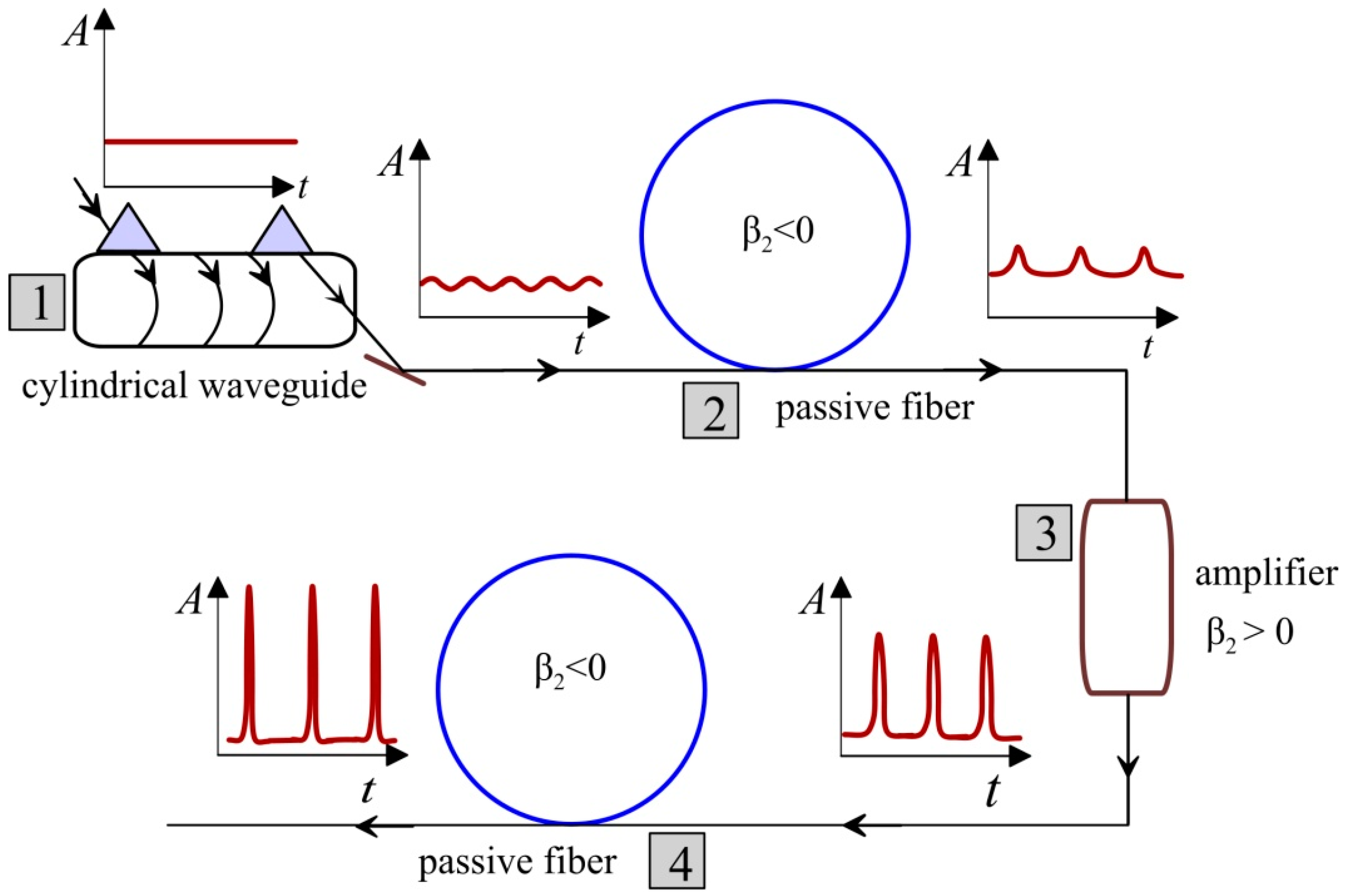
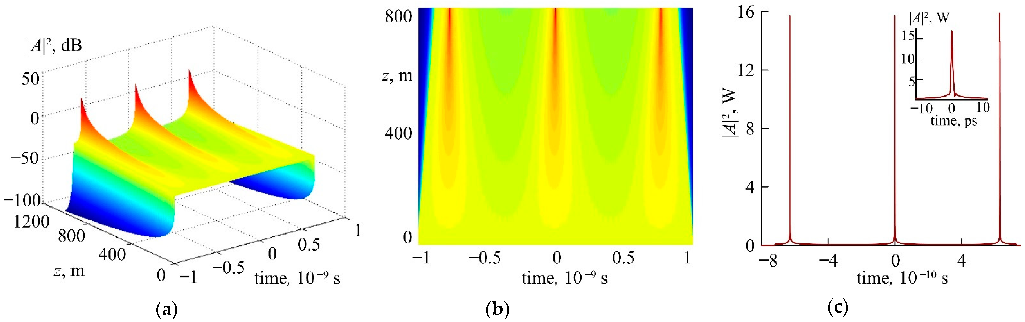
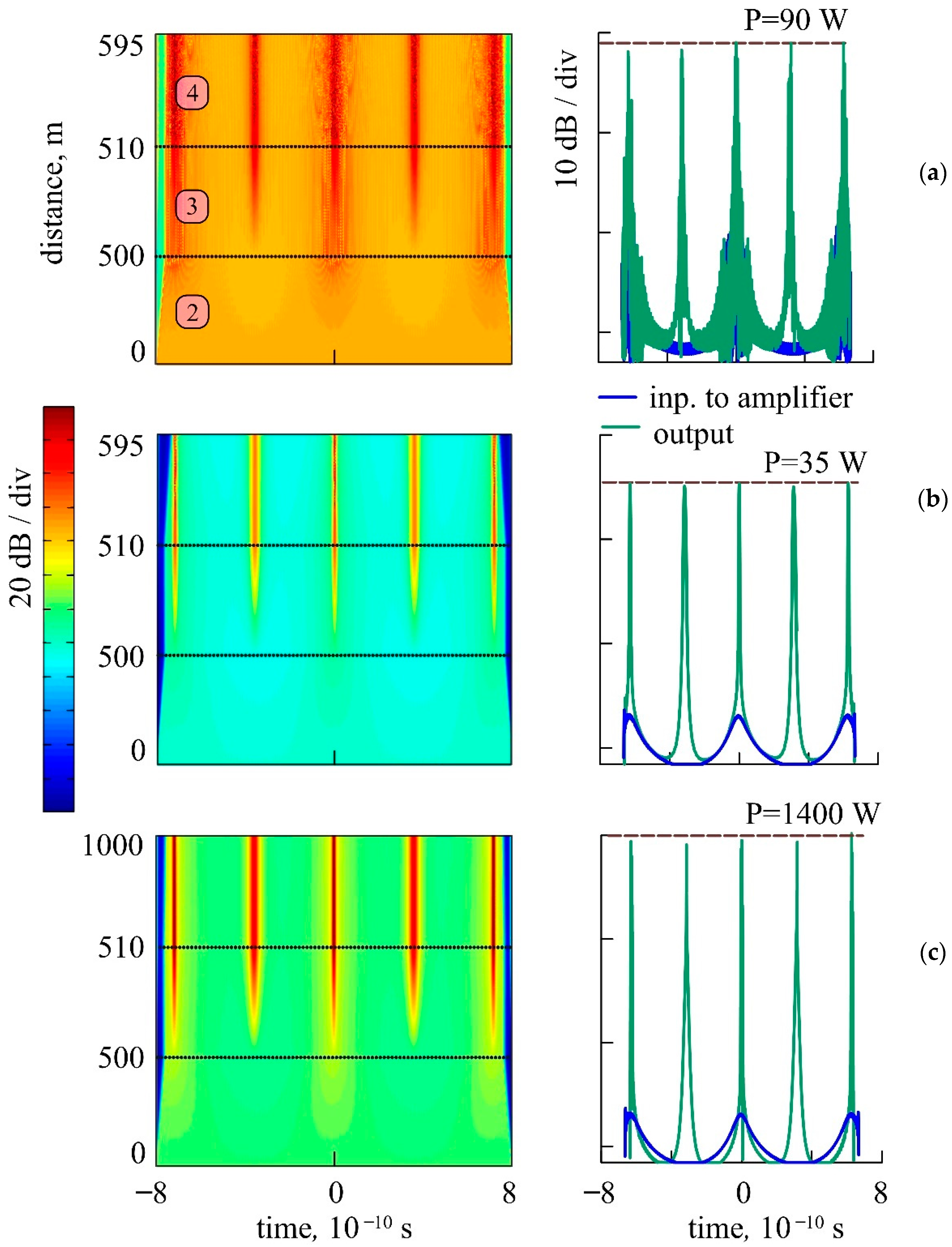
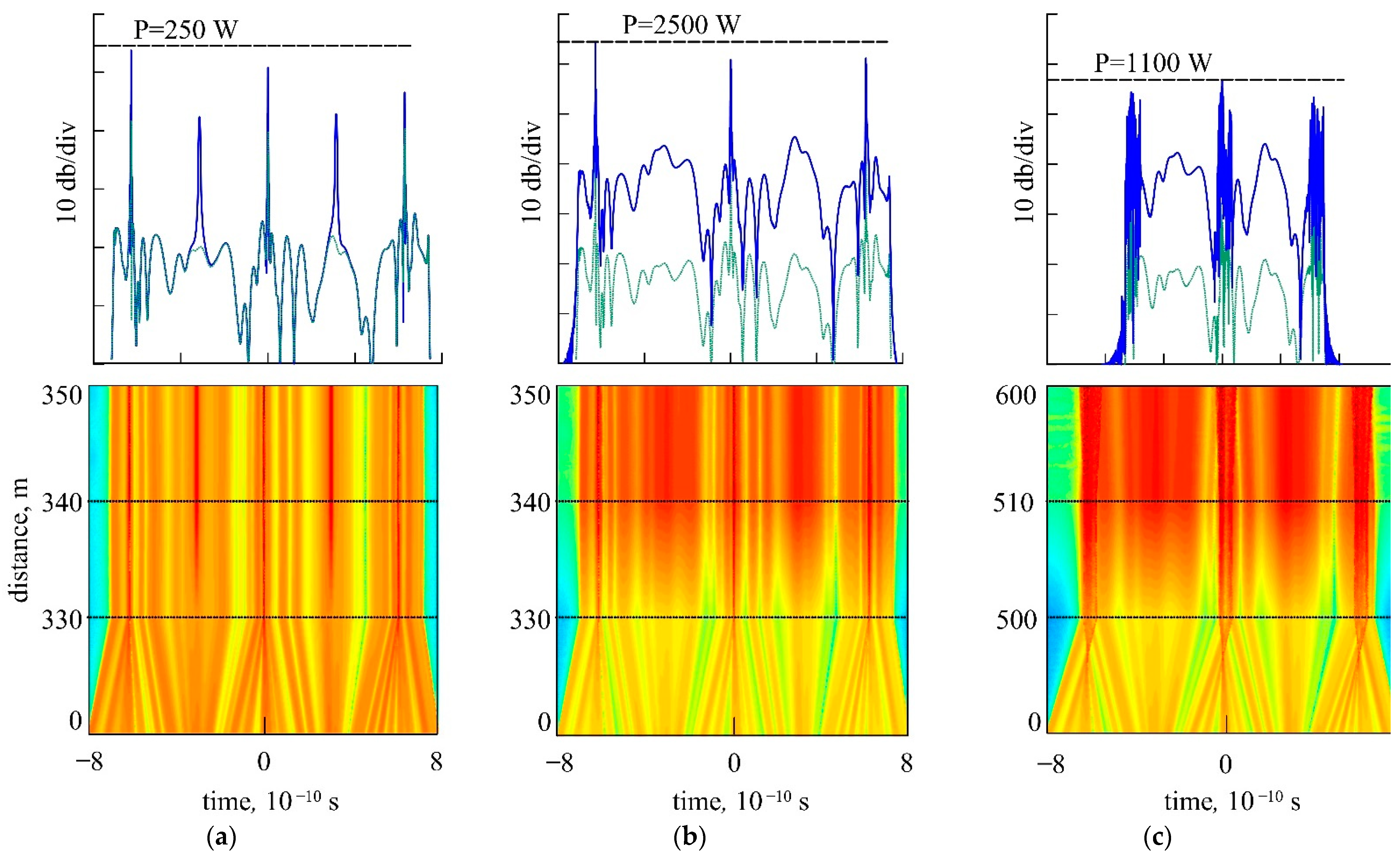
3. Cascaded Fiber Configuration for Generation of Subpicosecond Pulse Trains

We considered the cylindrical waveguide as a part of the cascadedoptical fiber configuration comprising also passive and active optical fiber segments. In this system, shown in Figure 2, the cylindrical waveguide structure with RRIW was responsible mainly for the frequency modulation of the propagating AWGM light described by Equation (2). The passive optical fibers with the anomalous group velocity dispersion (GVD) were used mostly as MI media for pulse shaping. The active (gain) fibers with normal dispersion were employed for peak power scaling. The spliced configuration as a whole enabled the generation of high-peak-power pulse trains.
In general, the light propagation in the passive and active fiber segments is described by the Schrödinger equation:
A z i d 2 ( 2 ) ( z ) 2 2 A τ 2 d 3 ( 2 ) ( z ) 6 3 A τ 3 + i R ( 2 ) ( z ) ( | A | 2 τ R | A | 2 τ ) A = g ( z ) A
where g ( z ) is the gain factor, τ R is the nonlinear response time characterizing the Raman self-scattering.
For standard uniform fibers, under the conditions of unsaturated optical gain in an active fiber ( g = c o n s t ), negligible Raman self-scattering, d 3 ( 2 ) 0 , and arbitrary boundary conditions, Equation (5) is reduced to the Gross–Pitaevskii equation:
A ¯ z i d 2 e f ( z ) 2 2 A ¯ τ 2 + i R e f ( z ) | A ¯ | 2 A ¯ = i S ( z ) τ 2 A ¯
where A ¯ ( τ , z ) A ( τ , z ) exp ( i δ cos ( Ω τ ) G z ) ,   τ = f ( z ) τ ,   G = g α d 2 ( 2 ) ,   S ( z ) = 2 α 2 d 2 ( 2 ) f 2 ( z ) ,   d e f ( z ) = d 2 ( 2 ) f 2 ( z ) , f ( z ) = exp ( 2 α d 2 ( 2 ) z ) , R e f = R ( 2 ) exp ( 2 g z ) , and α =   δ   Ω 2 / 2 .
In the next sections, we will explore transformation of a low power weakly modulated light propagating through four system cascades into the train of picosecond pulses with a kilowatt peak power. The numerical simulations are performed using the split-step Fourier method [11]. Simulations of the input light transformation into the frequency-modulated low-amplitude pulses in the cylindrical waveguide (cascade 1) are based on Equation (2). The processes of MI and optical amplification in the fiber cascades 2–4 are simulated based on Equation (5). It is worth noting that the simplified Equation (6) is also used for an advanced determination of the fiber point, where the peak pulse amplitude gets its maximum. This point depends on the phase modulation depth δ ( l ) m β ξ m n 0 ( 1 ) ω 0 l / v m and is determined as the point z c o m p of the Equation (6) singularity [9,10]:
z c o m p | 2 δ ( l ) Ω 2 d 2 ( 2 ) | | 2 v m m n 0 ( 1 ) ω 0 Ω 2 l d 2 ( 2 ) |
Relation (7) demonstrates that, for the considered configuration, the use of a fiber with the maximal anomalous dispersion is preferable as it ensures the fastest achievement of maximal compression of generated pulses.
The first element of the considered cascaded configuration was a cylindrical waveguide with RRIW. It was used to convert the input CW light into a train of phase modulated pulses possessing negligible intensity amplitude. Introduced at a small angle into the waveguide, the input light covers the optical path, ξ , along a spiral trajectory acquiring a deep frequency modulation characterized by a dimensionless parameter | δ | π / 2 . Under the above conditions, the modulation depth can be as high as δ 3 × 10 3 . To the best of our knowledge, there are no phase modulators (including running wave modulators) possessing similar characteristics. The standard phase modulator can be described by the transmission function f = exp ( i δ cos Ω t ) , where δ and Ω are the modulation coefficient and frequency, respectively [29]. In order to obtain pulse generation in the proposed configuration at the GVD | d 2 | ~ 10 26   s 2 / m over lengths less than 1   km , | δ | Ω 2 > 10 23   s 2 has to be fulfilled (see Relation (7)). However, in standard modulators, e.g., based on LiNbO3, the modulation length is limited as L m π c / 2 n 0 Ω [29,30]. As a result, the upper limit of modulation depth is defined by δ m a x ~ Δ n m a x ω 0 / Ω < 10 4 ω 0 / Ω , where Δ n m a x is the maximal change of the refractive index. At Δ n m a x ~ 10 4 10 6 , | δ m a x | < 1 and, as a result, | δ m a x Ω 2 | < 10 4 ω 0 Ω < 10 23   s 2 . Since the standard modulators are unable to provide the required modulation depth, we assume them to be unsuitable for the proposed configuration.
Then the light pulses formed in cascade 1 propagate through the fiber possessing anomalous GVD. At this stage, the light pulses transform into a train of amplitude pulses with the repetition rate Ω. If the fiber is long enough, the formed pulse train becomes well pronounced with a distinctive separation into individual subpicosecond pulses. The fiber length corresponding to this case is estimated from (7) and depends on the fiber GVD, modulation frequency, and frequency modulation depth. The numerical simulation results shown in Figure 3 are in good agreement with the simplified Equation (7).
We consider a narrow-band, quasi-continuous, weakly modulated signal introduced into cascade 1 that is expressed as [9,10,11,14]:
A ( z ( 1 ) = 0 ,   τ ) P 0 ( 1 + Δ cos ( Θ τ ) )
where Δ = 10 4 is the input signal modulation depth, Θ = 10 12   s 1 is the input signal modulation frequency. The cylindrical waveguide dispersion parameters used for calculations are d 2 = 10 26   s 2 / m , d 3 = 10 41   s 3 / m , m β = 10   m 1 , ξ = 300   m , Ω = 4 × 10 9   s 1 , the length of light propagation in the cylinder waveguide is l 1   cm , and the input optical signal power is P = 0.1   W . The final frequency modulation depth is δ 3 × 10 3 . We assume the AWGM Q -factor in the cylinder waveguide to be ~ 10 9 . The passive fiber dispersion parameters are d 2 = 10 26   s 2 / m ; d 3 = 10 40   s 3 / m . In all cascade elements, the Kerr nonlinearity and nonlinear response time are assumed to be R ( 2 ) = 3 × 10 3   W 1 m 1 and τ R = 3 × 10 15   s , respectively. In this case, an ultrashort pulse train was generated at the length of 800 m as shown in Figure 4.
One can see that the peak power increased sharply at the final fiber length during the short time interval. At the cascade 2 output, the peak power was more than two orders of magnitude higher than the power of input signal introduced into the system. We found that, under the used conditions, the input signal modulation depth (in the range of 10 6 10 1 ) did not affect the dynamics of ultrashort pulse formation.
In order to generate a train of pulses with higher peak power, an active fiber (amplifier) and a section of passive fiber were added into the system as the third and fourth fiber cascades, as shown in Figure 2. While propagating in the pumped active fiber, the formed pulses experienced amplification and the pulse peak power increased adiabatically. In the last system cascade, the amplified pulses were finally compressed. Using this technique, the pulse train peak power could be drastically increased without deformation of the pulse shape.
The parameters used for numerical simulations were the same for the active (cascade 3) and passive (cascades 2, 4) fibers, except for the normal GVD d 2 = 10 26   s 2 / m used for the active fiber.
Let us consider the pulse train generation in the cascaded configuration with different passive fiber lengths (cascade 2): 50 (a), 500 (b), 1000 m (c, d) and the active fiber (cascade 3) length of 10 m (Figure 5). One should note that initial formation of pulses from the frequency modulated light occurred at relatively short fiber lengths < 10 m. Evolution of the pulse shape in the considered cascade is shown in Figure 5 (left). The corresponding pulse shapes at the input of cascade 2 and system output are presented in Figure 5 (right). The gain bandwidth was Δ ω l = 10 12   s 1 for (a–c) and Δ ω l = 4 × 10 13   s 1 (d). Dashed lines are the peak power of generated pulses.
The numerical analysis shows (Figure 3, Figure 4, Figure 5, Figure 6, Figure 7 and Figure 8) that the length along which the pulses are generated is described with high accuracy by Relation (7) and is determined mainly by the second-order GVD d 2 , frequency Ω, and depth m of AWGM modulation. In this case, the Kerr nonlinearity parameter within a wide range has a minor effect on the length along which the pulses are generated. Thus, we can say that the dynamics of pulse formation depends on the parameter μ = R ( 2 ) P s , where P s is the radiation average power after passage through an amplifier (cascade 3). In the case in which μ is much less than 10 4   m 1 , no pulse train was generated. At μ 1   m 1 , the modulated CW was destroyed without pulse generation. Within a wide range, 10 4   m 1 μ < 10 1   m 1 , the Kerr nonlinearity parameter slightly affected the length of USP train formation z c o m p . The pulse repetition rate with high accuracy was equal to Ω (i.e., the frequency of RRIW generated in the cylindrical waveguide).
Thus, we can assume that, in the proposed configuration, the modulation instability induced by the four-wave mixing plays a minor role in the USP train generation. A key role is played by the phase modulation achieved in the cylindrical waveguide due to the interaction between AWGM and RRIW.
Noteworthily, in the proposed cascaded configuration, the Kerr nonlinearity parameter had a minor effect on the length along which the pulses are generated but significantly affected the generated pulse duration and peak amplitude. The value R ( 2 ) = 3 × 10 3   W 1 m 1 corresponding to the standard Kerr nonlinearity parameters of the optical fibers [11,14] was chosen for calculation in all segments of the cascaded configuration (Figure 4 and Figure 5). A high Kerr nonlinearity parameter, R ( 2 ) > 10 2   W 1 m 1 , leads to immediate destruction of the undeformed pulse train.
The higher the nonlinearity parameter, the stronger the noise phase and amplitude modulations. The peak power was relatively low (Figure 6a). However, the decrease of the nonlinearity parameter enabled the generation of higher peak power pulses. On the other hand, at R ( 2 ) < 10 3   W 1 m 1 (Figure 6b,c), the peak power of generated pulses can increase by more than an order of magnitude causing no significant deterioration of their shape. Therefore, at the lower nonlinearity parameters, a higher gain could be obtained. Thus, the pulses of higher peak power and energy can be generated. In this context, fibers with nonlinearity lower than that in the standard fibers such as large mode area single-mode photonic-crystal fibers [11,14] and the GRIN fibers with a parabolic (cross-sectional) refractive index profile [31,32,33,34,35] seemed suitable for the proposed configurations. The GRIN fibers were assumed to be the most promising for generation of the pulse trains with peak power > 1 kW. A more detailed discussion of this issue will be published elsewhere.
One can see that the peak power of the generated pulse train depends on the passive fiber length (cascade 2) (Figure 5a–c) providing formation of the pulses from the AWGM radiation with strong phase modulation (i.e., | δ | π / 2 ) generated in the cylindrical waveguide. For example, at the gain bandwidth Δ ω l = 10 12   s 1 and passive fiber length l = 1000   m , at the cascade 2 output, the pulses exhibited a peak power increase of about three orders of magnitude. For large gain bandwidth Δ ω l = 4 × 10 13   s 1 , Figure 5d, the peak power increased up to a few kilowatts. The generation of a train of pulses with the repetition rate equal to the RRIW modulation frequency was available with a low-power noise introduced into the cylinder instead of the weakly modulated CW light (Figure 6, inset, blue curve). In this case, the subpicosecond pulse generation is governed by the same mechanism as described above for the stable pulse trains generated through the transformation of a strong linear phase modulation into an amplitude modulation.
Figure 7a,b shows the formation of a pulse train in cascades 1 and 2 in the passive fiber length of 400 m at the fiber parameters used in the previous section. In comparison with the CW light input, the use of noise as an input optical signal significantly limited the flexibility of the system parameters needed for effective pulse train generation. Although the pulse train generation from the noise optical signal differed from the generation initiated by the CW light, the achieved pulse peak powers in both cases were nearly the same. One can see in Figure 7c that the pulses generated from noise also demonstrate a picosecond duration and peak power nearly two orders of magnitude higher than the input power. However, the pronounced noise pedestal deteriorated the pulse shape quality.
In the cascaded configurations with amplification, an increase of the peak power up to kilowatts was achievable (Figure 8). In this case, a perfect optimization of the passive fiber lengths, gain factor, and gain bandwidth was required.
Figure 8 presents the pulse evolution and the corresponding pulse shapes at the cascaded system output calculated with the gain factor g ~ 0.3   m 1 , gain bandwidth Δ ω l = 10 12   s 1 (a), and Δ ω l = 4 × 10 13   s 1 (b, c). One can see that with the passive fiber (cascade 2) length of 330 m, an increase of Δ ω l led to an increase of the peak power (Figure 8b) without degradation of the pulse quality. For longer fibers, a broad gain bandwidth is undesirable as it leads to a sharp peak power decrease and destroys the pulse train, as shown in Figure 8c.
Importantly, the higher-order dispersion and nonlinear effects have a minor effect on the repetition rate of the generated pulses and their amplitude. Therefore, the dynamics of USP generation at the parameters typical for standard fibers τ R 3   fs ,   d 3 = 10 41   s 3 / m was almost the same as the dynamics of USP generation at τ R = 0 ,   d 3 = 0 .

4. Conclusions

In this study, we have demonstrated generation of the subpicosecond pulses in the cascaded fiber configuration comprising (as cascade 1) the cylindrical waveguide with RRIW responsible for initial formation of the CW light with a deep frequency modulation | δ | π / 2 . It is shown that the pulses with the peak power by orders of magnitude higher than the input power can be generated through the modulation instability directly from the input CW light. Similar generation of subpicosecond pulse trains with the comparable peak power level is also achievable with a low-amplitude noise signal introduced into the cylindrical waveguide. However, in this case, a proper combination of the fiber system parameters such as the passive fiber length, gain bandwidth, and gain factor should be provided.
In fact, the proposed mechanism is similar to mode-locking taking place outside the source demonstrated earlier as the Fourier synthesis obtained with the self-swiping fiber lasers [36,37]. Specifically, the generated FM light is resistive to nonlinear perturbations and could be amplified up to high peak powers following the singular solution of Equation (7). The reported pulse train generators are attractive for material processing laser systems, lidars, compact charged-particle accelerators, and laser isotope separation systems. In this context, the cascaded configurations comprising the cylindrical waveguide with RRIW and active graded-index large mode area ( 1000   μ m 2 ) fibers [31,32,33,34,35] are of particular interest. A train of pulses with a GHz repetition rate and peak power much higher than 1 kW could be delivered with such fibers. It is worth noting that the use of a standard pair of diffraction gratings (as cascade 4) is preferable to an anomalous dispersion fiber in this case. Importantly, the pulses considered in this work possess some similarity with the rogue waves (also known as freak waves). Such kind of phenomenon is of fundamental importance [38,39,40] and, in the future, could be also implemented with microcavities [6,7,8], ring lasers [11,12,41], or running wave modulators [42,43]. The considered generators of high-repetition-rate pulses could be promising for radio photonics technologies [44,45,46,47].

Author Contributions

Conceptualization, I.Z. and A.F.; methodology, I.Z.; software, A.A. (Aleksandr Alekseev); validation, M.Y. and V.K.; formal analysis, I.Z. and D.K., investigation, D.K. and A.A. (Aleksei Abramov); resources, V.K. and A.D.; data curation, A.D. and A.A. (Aleksei Abramov); writing—original draft preparation, A.F.; writing—review and editing, M.Y.; visualization, A.A. (Aleksei Abramov) and M.Y.; supervision, I.Z.; project administration, I.Z.; funding acquisition, A.A. (Aleksei Abramov), I.Z. and A.F. All authors have read and agreed to the published version of the manuscript.

Funding

This research was funded by The Ministry of Science and Higher Education of the Russian Federation, grant number 075-15-2021-581. A.A. (Aleksei Abramov) thanks the RF President Fellowship, fellowship number SP-4058.2021.5. The work of I.Z, A.F. and D.K. is supported by The Russian Science Foundation, grant number 18-12-00457P.

Institutional Review Board Statement

Not applicable.

Informed Consent Statement

Not applicable.

Data Availability Statement

Not applicable.

Conflicts of Interest

The authors declare no conflict of interest.

References

  1. Torchigin, V.P. Amplification of light pulses in waveguides with a periodically varying refractive index. Quantum Electron. 1995, 22, 509–510. [Google Scholar] [CrossRef]
  2. Sychugov, V.A.; Torchigin, V.P.; Tsvetkov, M.Y. Whispering-gallery waves in optical fibres. Quantum Electron. 2002, 32, 738–742. [Google Scholar] [CrossRef]
  3. Torchigin, V.P.; Torchigin, S.V. Optical solitons appearing during propagation of whispering-gallery waves. Quantum Electron. 2003, 33, 913–918. [Google Scholar] [CrossRef]
  4. Zolotovskii, I.O.; Korobko, D.A.; Lapin, V.A.; Sementsov, D.I. Modulation instability of pulsed radiation in an optical waveguide in the presence of the traveling refractive index wave. Opt. Spectrosc. 2016, 121, 277. [Google Scholar] [CrossRef]
  5. Snyder, A.W.; Love, J. Optical Waveguide Theory; Springer US: New York, NY, USA, 1983; 734p. [Google Scholar]
  6. Foreman, M.R.; Swaim, J.D.; Vollmer, F. Whispering gallery mode sensors. Adv. Opt. Photon. 2015, 7, 168–240. [Google Scholar] [CrossRef]
  7. McCall, S.L.; Levi, A.F.J.; Slusher, R.E.; Pearton, S.J.; Logan, R.A. Whisperinggallery mode microdisk laser. Appl. Phys. Lett. 1992, 60, 289–291. [Google Scholar] [CrossRef]
  8. Vahala, K.J. Optical microcavities. Nature. 2003, 24, 839–846. [Google Scholar] [CrossRef] [PubMed]
  9. Zolotovskii, I.O.; Korobko, D.A.; Lapin, V.A.; Mironov, P.P.; Sementsov, D.I.; Yavtushenko, M.S.; Fotiadi, A.A. Generation of ultrashort laser pulses through a resonant interaction of quasi-continuous wave packet with running refractive index wave. J. Opt. Soc. Am. B 2019, 36, 2877–2883. [Google Scholar] [CrossRef]
  10. Zolotovskii, I.O.; Korobko, D.A.; Lapin, V.A.; Mironov, P.P.; Sementsov, D.I.; Fotiadi, A.A.; Yavtushenko, M.S. Generation of subpicosecond pulses due to the development of modulation instability of whispering-gallery-mode wave packets in an optical waveguide with a travelling refractive-index wave. Quantum. Electron. 2018, 48, 818–822. [Google Scholar] [CrossRef]
  11. Agrawal, G.P. Nonlinear Fiber Optics, 4th ed.; Springer: New York, NY, USA, 2007; 530p. [Google Scholar]
  12. Chernikov, S.V.; Mamyshev, P.V. Femtosecond soliton propagation in fibers with slowly decreasing dispersion. J. Opt. Soc. Am. B 1991, 8, 1633. [Google Scholar] [CrossRef]
  13. Zolotovskii, I.O.; Lapin, V.A.; Sementsov, D.I.; Fotiadi, A.A.; Popov, S.V. Generation of high frequency trains of chirped soliton-like pulses in inhomogeneous and cascaded active fiber configurations. Opt. Commun. 2018, 426, 333–340. [Google Scholar] [CrossRef]
  14. Kivshar, Y.S.; Agrawal, G.P. Optical Solitons: From Fibers to Photonic Crystals; Academic Press: New York, NY, USA, 2003; p. 125. [Google Scholar]
  15. Dalfovo, F.; Giorgini, S.; Pitaevskii, L.P.; Stringari, S. Theory ofBose-Einstein condensation in trapped gases. Rev. Mod. Phys. 1999, 71, 463. [Google Scholar] [CrossRef] [Green Version]
  16. Abdullaev, F.K.; Darmanyan, S.A.; Garnier, J. Modulation instability of electromagnetic waves in inhomogeneous and in discrete media. Prog. Opt. 2002, 44, 303. [Google Scholar]
  17. Inouye, S.; Andrws, M.R.; Stenger, J.; Miesner, H.-J.; Stamper-Kurn, D.M.; Ketterle, W. Observation of Feshbach resonances in a Bose-Einstein condensate. Nature 1998, 392, 151. [Google Scholar] [CrossRef]
  18. Torchigin, V.P. Light amplification in optical waveguides and cavities formed by an acoustic wave. J. Tech. Phys. 1996, 8, 107. [Google Scholar]
  19. Torchigin, V.P. Conversion of light in a focon with an acoustic wave as the pump. J. Tech. Phys. 1996, 4, 128. [Google Scholar]
  20. Torchigin, V.P. Possibility of using the interaction of acoustic and light waves in optical fibers to generate short light pulses. Quantum Electron. 1993, 3, 235–240. [Google Scholar] [CrossRef]
  21. Abramov, A.S.; Kadochkin, A.S.; Sannikov, D.G.; Zolotovskii, I.O.; Yavtushenko, M.S.; Moiseev, S.G.; Svetukhin, V.V.; Fotiadi, A. Cylindrical silicon near-IR optical amplifier driven by direct current. J. Opt. Soc. Am. B 2020, 37, 2314–2318. [Google Scholar] [CrossRef]
  22. Goutzoulis, A.P.; Pape, D.R. Design and Fabrication of Acousto-Optic Devices; Marcel Dekker: New York, NY, USA, 1994; p. 68. [Google Scholar]
  23. Savchenkov, A.; Strekalov, D.; Ilchenko, V.; Maleki, L.; Grudinin, I.; Matsko, A. Ultra high Q crystalline microcavities. Opt. Commun. 2006, 265, 33–38. [Google Scholar]
  24. Llopis, O.; Merrer, P.H.; Bouchier, A.; Saleh, K.; Cibiel, G. High-Q optical resonators: Characterization and application to stabilization of lasers and high spectral purity microwave oscillators. Proc. SPIE 2010, 7579, 75791B. [Google Scholar]
  25. Birks, T.F.; Knight, J.C.; Dimmik, T.E. High-resolution measurement of the fiber diameter variations using whispering gallery modes and no optical alignment. IEEE Photon. Technol. Lett. 2000, 12, 182. [Google Scholar] [CrossRef]
  26. Sumetsky, M. Nanophotonics of optical fibers. Nanophotonics 2013, 2, 393. [Google Scholar] [CrossRef]
  27. Sumetsky, M. Delay of Light in an Optical Bottle Resonator with Nanoscale Radius Variation: Dispersionless, Broadband, and Low Loss. Phys. Rev. Lett. 2013, 111, 163901. [Google Scholar] [CrossRef] [Green Version]
  28. Watts, A.L.; Singh, N.; Poulton, C.G.; Magi, E.C.; Kabakova, I.V.; Hudson, D.D.; Eggleton, B.J. Photoinduced axial quantization in chalcogenide microfiber resonators. J. Opt. Soc. Am. B 2013, 30, 3249. [Google Scholar] [CrossRef]
  29. Yariv, A.; Yeh, P. Photonics: Optical Electronics in Modern Communications; Oxford University Press: Oxford, UK, 2007. [Google Scholar]
  30. Petrov, V.M.; Agruzov, P.M.; Lebedev, V.V.; Il’ichev, I.V.; Shamray, A.V. Broadband integrated optical modulators: Achievements and prospects. Phys. Usp. 2021, 64, 722–739. [Google Scholar] [CrossRef]
  31. Mafi, A.J. Pulse propagation in a short nonlinear graded-index multimode optical fiber. Lightw. Technol. 2012, 30, 2803. [Google Scholar] [CrossRef]
  32. Renninger, W.H.; Wise, F.W. Optical solitons in graded-index multimode fibers. Nat. Commun. 2013, 4, 1719. [Google Scholar] [CrossRef] [PubMed] [Green Version]
  33. Krupa, K.; Tonello, A.; Barthélémy, A.; Couderc, V.; Shalaby, B.M.; Bendahmane, A.; Millot, G.; Wabnitz, S. Observation of geometric parametric instability induced by the periodic spatial self-imaging of multimode waves. Phys. Rev. Lett. 2016, 116, 183901. [Google Scholar] [CrossRef] [Green Version]
  34. Krupa, K.; Tonello, A.; Shalaby, B.M.; Fabert, M.; Barthélémy, A.; Millot, G.; Wabnitz, S.; Couderc, V. Spatial beam self –cleaning in multimode fibres. Nat. Photonics 2017, 11, 237. [Google Scholar] [CrossRef] [Green Version]
  35. Seeds, A.J.; Williams, K.J. Microwave photonics. IEEE J. Lightw. Technol. 2006, 24, 4628–4641. [Google Scholar] [CrossRef]
  36. Lobach, I.A.; Kablukov, S.I.; Podivilov, E.V.; Fotiadi, A.A.; Babin, S.A. Fourier synthesis with single-mode pulses from a multimode laser. Opt. Lett. 2015, 40, 3671. [Google Scholar] [CrossRef] [PubMed]
  37. Lobach, I.A.; Drobyshev, R.V.; Fotiadi, A.A.; Podivilov, E.V.; Kablukov, S.I.; Babin, S. Open-cavity fiber laser with distributed feedback based on externally or self-induced dynamic gratings. Opt. Lett. 2017, 42, 4207–4210. [Google Scholar] [CrossRef]
  38. Kharif, C.; Pelinovsky, E.; Slunyaev, A. Rogue Waves in the Ocean; Springer: Berlin/Heidelberg, Germany, 2009. [Google Scholar]
  39. Solli, D.R.; Ropers, C.; Koonath, P.; Jalali, B. Optical rogue waves. Nature 2007, 450, 1054. [Google Scholar] [CrossRef] [PubMed]
  40. Moses, J.; Malomed, B.A.; Wise, F.W. Self-steepening of ultrashort optical pulses without self-phase modulation. Phys. Rev. A 2007, 76, 021802. [Google Scholar] [CrossRef]
  41. Agrawal, G. Applications of Nonlinear Fiber Optics; Academic Press: New York, NY, USA, 2008; p. 508. [Google Scholar]
  42. Krahenbuhl, R.; Burns, W.K. Modeling of broad-band traveling-wave optical-intensity modulators. IEEE Trans. Microw. Theory Tech. 2000, 48, 860–864. [Google Scholar] [CrossRef]
  43. Kawanishi, T.; Sakamoto, T.; Izutsu, M. High-speed control of lightwave amplitude, phase, and frequency by use of electrooptic effect. IEEE J. Select. Top. Quantum Electron. 2007, 13, 79–91. [Google Scholar] [CrossRef]
  44. Lim, C.; Nirmalathas, A.; Bakaul, M.; Gamage, P.; Lee, K.L.; Yang, D.; Novak, D.; Waterhouse, R. Fiber-wireless networks and subsystem technologies. J. Lightw. Technol. 2010, 8, 390–405. [Google Scholar] [CrossRef]
  45. Wake, D.; Nkansah, A.; Gomes, N.J. Radio over fiber link for next generation wireless system. J. Lightw. Technol. 2010, 28, 2456–2464. [Google Scholar] [CrossRef] [Green Version]
  46. Wake, D.; Dupont, S.; Lethien, C.; Vilcot, J.; Decoster, D. Radio frequency transmission over multimode fibre for distributed antenna system applications. Electron Lett. 2001, 37, 1087–1089. [Google Scholar] [CrossRef]
  47. Geddes, C.G.; Toth, C.; Tilborg, J.; Esarey, E.; Schroeder, C.B.; Bruhwiler, D.; Nieter, C.; Cary, J.; Leemans, W.P. High-quality electron beams from a laser wakefield accelerator using plasma-channel guiding. Nature 2004, 431, 538. [Google Scholar] [CrossRef]
Figure 1. Geometry of optical radiation entering the cylindrical waveguide (a) waveguide cross section, (b) top view of the prism and fiber). 1—waveguide, 2—prism, 3—input radiation, 4—surface wave, 5—cylinder axis, 6—cylinder cross section; is the angle between the direction of radiation input into the cylindrical waveguide, 3 and cylinder cross-section, 6. V ,   V z , and  V x are the velocity and its longitudinal and transverse components, respectively.
Photonics 08 00484 g001
Figure 2. Cascaded configuration for ultrashort pulse train generation: 1—wave guide with RRIW, 2,4—anomalous GVD passive fiber, 3—active fiber with a positive GVD.
Photonics 08 00484 g002
Figure 3. Critical length of the anomalous GVD fiber as a function of the optical path ξ in the cylindrical waveguide with RRIW at different modulation frequencies Ω, d 2 = 10 26   s 2 / m , β = 4 × 10 6   m 1 ,   m = 5 × 10 5 . The curves are calculations using Formula (7), the points are the results of numerical calculation.
Photonics 08 00484 g003
Figure 4. Pulse train formation from low-amplitude noise in cascade 2 (a,b). Pulse shape at the cascade 2 output, inset—enlarged central pulse of train (c).
Photonics 08 00484 g004
Figure 5. Evolution of time envelope profile in the fiber cascade (2–4) with different passive fiber lengths (cascade 2): 50 (a), 500 (b), 1000 m (c), and (d) and amplifier length of 10 m. (Right) Time profiles of pulse trains in semi-logarithmic scale at the amplifier input (blue curves) and output (green curves). Gain bandwidth is Δ ω l = 10 12   s 1 (ac) and Δ ω l = 4 × 10 13   s 1 (d) at g 0.3   m 1 .
Photonics 08 00484 g005
Figure 6. Evolution of time envelope profile in the fiber cascade (2–4) with different value of Kerr nonlinearity in a cascade 2–4: 0.1 (a),   10 4 ( W × m ) 1 (b,c), and amplifier length of 10 m. (Right) Time profiles of pulse trains in semi-logarithmic scale at the amplifier input (blue curves) and output (green curves). Gain bandwidth is Δ ω l = 10 12 s 1 (ac) at g ~ 0.3   m 1 , input power P 0 = 0.1   W (a,b), 1.0   W (c).
Photonics 08 00484 g006
Figure 7. Pulse train formation from low-amplitude noise in cascade 2 (a,b). Pulse shape at the cascade 2 output (c).
Photonics 08 00484 g007
Figure 8. Pulse evolution in the fiber cascades 2–4 and pulse shapes at the system output at different length of the passive fiber (cascade 2): 330 m (a,b) and 500 m (c), the amplifier length is 10 m. The gain bandwidth is Δ ω l = 10 12   s 1 (a) and Δ ω l = 4 × 10 13   s 1 (b,c).
Photonics 08 00484 g008
Publisher’s Note: MDPI stays neutral with regard to jurisdictional claims in published maps and institutional affiliations.

