Review

Progress of Waveguide Ring Resonators Used in Micro-Optical Gyroscopes

1
Engineering Research Center for Semiconductor Integrated Technology, Institute of Semiconductors, Chinese Academy of Sciences, Beijing 100083, China
2
Center of Materials Science and Optoelectronics Engineering, University of Chinese Academy of Sciences, Beijing 100049, China
3
School of Microelectronics, University of Chinese Academy of Science, Beijing 100049, China
4
State Key Laboratory for Superlattices and Microstructures, Institute of Semiconductors, Chinese Academy of Science, Beijing 100083, China
5
Beijing Academy of Quantum Information Science, Beijing 100193, China
6
School of Electronics, University of Chinese Academy of Science, Beijing 100049, China
*
Authors to whom correspondence should be addressed.
Photonics 2020, 7(4), 96; https://doi.org/10.3390/photonics7040096
Submission received: 7 August 2020 / Revised: 13 October 2020 / Accepted: 13 October 2020 / Published: 26 October 2020

Abstract

:
Micro-optical gyroscopes (MOGs) are a type of high-accuracy gyroscope, which have the advantages of miniaturization, low cost, and satisfactory operating power. The quality factor (Q) of the waveguide ring resonators (WRRs) is very important to the performance of MOGs. This paper reviews various MOGs using WRRs made from different materials, including silica, indium phosphide, calcium fluoride, and polymer WRRs. The different architectures of the MOGs are reviewed, such as double-ring resonator MOGs and multiple-ring resonator MOGs. Candidate high-Q WRRs for MOGs, including silicon nitride, lithium niobite, calcium fluoride, and magnesium fluoride WRRs, are also reviewed. The manufacturing process, Q, and integration density values are compared. Summarizing the advanced WRRs and calculating the shot-noise-limited sensitivity are helpful processes in selecting suitable materials to fabricate MOGs.

1. Introduction

Optical gyroscopes making use of the Sagnac effect have played important roles in navigation and positioning systems [1]. Compared to micromechanical gyros, optical gyroscopes show high tolerance to acceleration and overload and have short warm-up times, among other factors [2]. Among these optical gyroscopes, laser gyros and fiber-optic gyros occupy most of the market. Although the accuracy levels of these two types of gyros are very high, their applications in integrated devices are limited by their large sizes. In order to enhance the competitiveness of optical gyros in small navigation systems, more requirements have been put forward in terms of the device sizes. For these reasons, micro-optical gyros (MOGs) were proposed, which utilize the optical waveguide ring resonators (WRRs) to detect the angular rotation rates [3].
MOGs can be divided into two types, i.e., active MOGs and passive MOGs. In active MOGs, the laser sources are placed in the optical paths of the WRRs, while in passive MOGs, the laser sources are placed outside. A main critical problem of active MOGs that needs to be solved is the lock-in effect, which leads to a null frequency difference between counterpropagating beams for small angular rotation rates [4]. Contrarily, the passive gyros do not suffer from this problem.
MOGs work on the principle of the Sagnac effect, as shown in Figure 1. When the WRR is not rotating (Figure 1, left panel), the optical paths for one round-trip have the same lengths for both clockwise (CW) and counterclockwise (CCW) beams in the WRR. As the WRR rotates (Figure 1, right panel), the optical paths traveled by CW and CCW beams will be different. When the ring rotates clockwise, the optical path of CW beam will be greater than that of the CCW beam for one round-trip. The difference in optical paths between CW and CCW beams can be expressed as:
Δ L = 4 A c 0 Ω = 2 Δ S
where A is the effective area of the WRR, c0 is the speed of light in the vacuum, Ω is the angular rotation rate of the WRR, and ΔS is the difference between the optical paths induced by the WRR rotation.
The difference between the resonant frequencies of CW and CCW beams induced by the Sagnac effect can be expressed as:
Δ f = f 0 n L Δ L = 4 A n L λ Ω
where f0 is the laser frequency, L is the circumference of the WRR, n is the effective index, and λ is the wavelength of the beams.
According to Equation (2), The Sagnac effect can be detected by tracking the difference between the resonant frequencies in a passive WRR excited by two coherent laser beams [5].
MOGs are composed of lasers, couplers, phase modulators, WRRs, and photodetectors. The system structure is shown in Figure 2. A laser beam is emitted from a narrow-linewidth laser and divided equally into two beams after passing through the coupler. The two beams are then injected into the WRR in the CW and CCW directions. There are two phase modulators (PMs) in the optical paths in the CW and CCW directions, which modulate the two beams before entering the WRR. The laser frequency is locked to the CCW beam frequency by using the lock-in Amplifier (LIA). By measuring the difference between the resonant frequencies of the CW and CCW beams induced by the Sagnac effect from PD2, we can obtain the output of the gyro.
Two parameters are used to characterize the performance of MOGs: the shot-noise-limited theoretical sensitivity and angle random walk (ARW) [1]. Shot-noise is a kind of random noise generated by the photoelectric conversion in photodetectors. The shot-noise-limited theoretical sensitivity is the smallest rotational angular velocity that the MOGs can detect. The ARW reflects the characteristics of white noises in the angular rate signals. The sensitivity can be influenced by many factors, including backscattering, back-reflection, polarization fluctuation, nonlinear Kerr effect, and laser frequency noise [6,7,8]. These parasitic effects deteriorate the performance of the MOGs. Major non-reciprocal noises are Rayleigh scattering noise and thermal fluctuations between CW and CCW beams [9]. Major reciprocal noises are laser frequency noises and detector dark current noises. For different platforms, the performance of the laser and detector will introduce various reciprocal noise, such as backscattering/back-reflection noises caused by impurities and cracks in the waveguide [10]. Two eigenstates of polarization (ESOP) exist in a WRR which both meet the resonance condition and two resonance dips can be excited. The polarization noises are affected by many factors, including the temperature fluctuation, the state of polarization (SOP) of the input light, and the polarization-maintaining quality of WRR. When the temperature changes, the phase difference between transverse electric (TE) mode and transverse magnetic (TM) mode changes and the resonance dips corresponding to the two ESOPs changes. When the two dips approach, the resonance curve shape is distorted. By adjusting the input light to be consistent of one of the ESOPs and increasing the degree of polarization of the input light, the resonance of depth can be increased [7]. The resonance curve shape is also distorted by the polarization crosstalk existing in the waveguide. It can be solved by using a polarization controller and polarization-maintaining waveguide [11]. It is encouraging that various parasitic effects have been solved successively. Compared to temperature fluctuations and noises, the signal introduced by the Sagnac effect is much smaller. The phase modulation technique is introduced to improve the readout system. The CW and CCW beams are modulated by PMs that have the same amplitudes but opposite phases at the same time. By using the phase modulation, the frequency difference between the laser frequency and the resonance frequency of the CW/CCW beams are transferred to the voltage amplitude detected by PD1/PD2. When the gyro is at the rotation state, the resonance frequency of CW and CCW varies in the opposite direction. When the laser frequency is locked to the CW frequency, the output of PD1 is a constant offset. However, the amplitude of the output of PD2 is proportional to the rotation rate [12]. Different phase modulation techniques have already been studied, such as the single-phase modulation technique [13,14,15], the double-phase modulation technique [16,17,18], and the hybrid-phase modulation technique [19,20].
WRR is the key rotation-sensing element in MOGs [21]. The shot-noise-limited sensitivity of MOGs is greatly related to the product of the Q factor and the footprint of WRR [22]. The waveguide propagation loss, directional coupler loss, and excess directional coupler power loss per pass influence the Q factor [23]. In recent years, many types of WRRs have been fabricated, such as bulk ring resonators [24] and 3D WRRs [25]. Since the current planar optical waveguide process is difficult to use to fabricate a large-area and high-Q ring resonator, it is necessary to discuss the current status and process development of the optical waveguide ring resonator. This will be of great help to the development of integrated MOGs in the future.

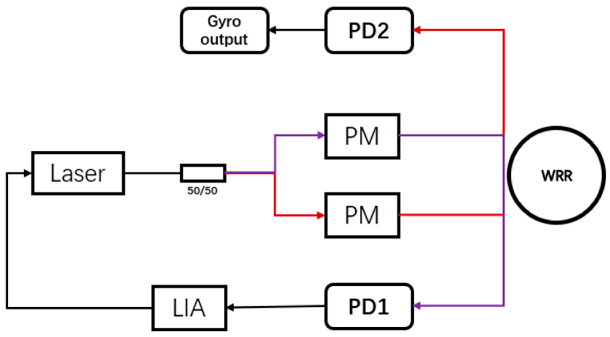
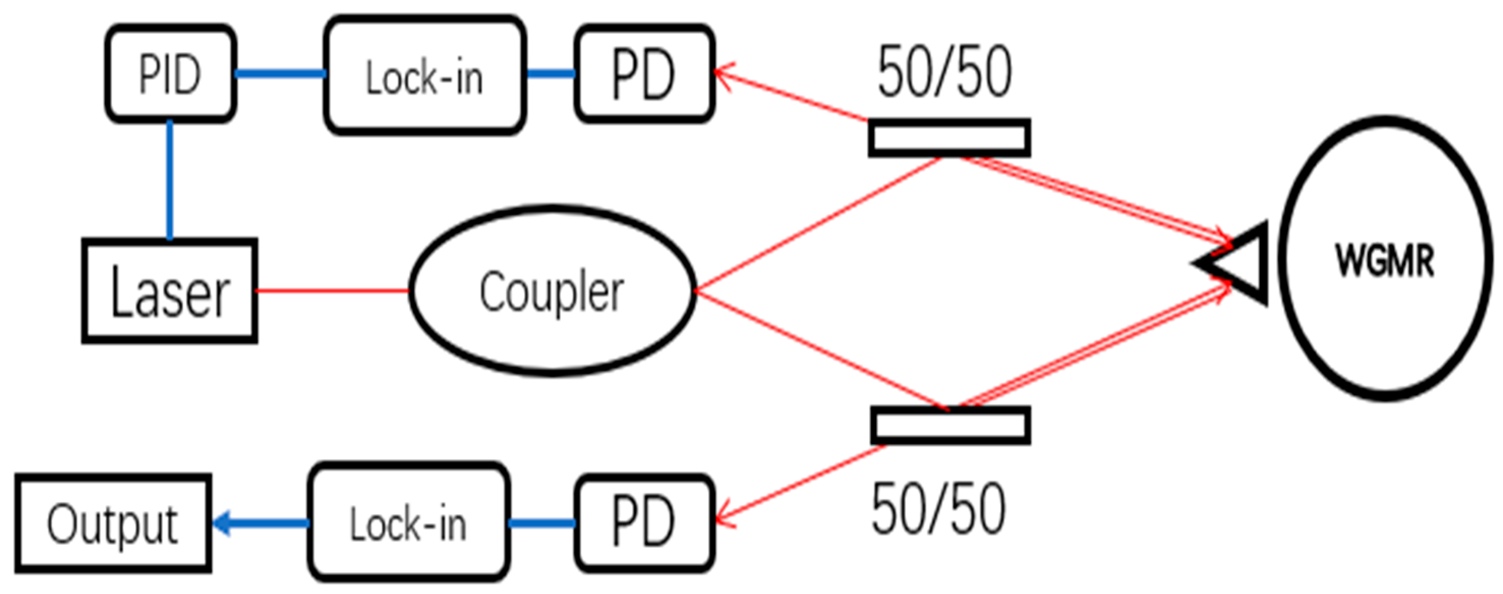
2. Waveguide Ring Resonators for MOGs

The shot-noise-limited sensitivity of MOGs is related to the product of the Q factor and the footprint of WRR. It indicates the smallest rotational angular velocity that MOGs could detect. It is given by [26]:
δ Ω = 1 d Q P p d 2 B h c 3 λ η × ( 3600 × 180 π )    ( d e g / h )
The ARW is given by [26]:
A R W = 1 d Q P p d 2 h c 3 λ η × ( 60 × 80 π )    ( d e g / h )
where d is the ring diameter, Ppd is the optical power at the input of photodetector in the readout system, η is the photodetector efficiency, B is the measurement bandwidth, λ is the sensor operating wavelength, c is the speed of light in the vacuum, and h is Plank’s constant.
The Q factor of resonator can be expressed as [23]:
Q = ( 2 π ν 0 T r t ) l 1
where Trt is the round-trip time of the resonator, ν0 is the free space frequency of light, and l is the fractional power loss per round trip. From Equation (5), the Q factor is significantly influenced by the propagation loss of waveguide and the coupling loss, therefore we also pay attention to the fabrication technology of WRRs.
In this section, three aspects of WRRs are reviewed: conventional WRRs that have been used in MOGs, new architectures of WRRs for MOGs, and the latest high Q resonators which are good candidates for MOGs.

2.1. Progress of Waveguide Ring Resonator Used in MOGs

The quality factor of the WRRs will greatly affect the performance of the MOGs. The prototypes of MOGs have been fabricated in [27,28,29,30]. In this section, we will introduce the WRRs that have been applied to MOGs using different materials, including silicon dioxide (SiO2), indium phosphide (InP), calcium fluoride (CaF2), and polymer.

2.1.1. Silica Waveguide Ring Resonator

As the earliest material used, SiO2 has the most mature planar processing technology. The mature process makes it possible to fabricate silica waveguides with a transmission loss as low as 0.1 dB/cm [26] so that WRRs of higher quality can be fabricated.
A high finesse WRR with a resonance depth close to 100% is proposed in [27]. The WRRs made of buried-type Ge-doped low-loss silica waveguides are fabricated with ring diameters of 7.9 cm and 2.5 cm. The size of the rectangular waveguide is 6 μm × 6 μm. Considering the waveguide bending loss and the coupling loss, the total loss of the resonant ring is 0.079 dB. By using single-polarized fiber instead of polarization-maintaining fiber at both ends of the coupled waveguide, the polarization extinction ratio increases from 10.7 dB to 18.9 dB, and the maximum sensitivity could reach 3.74°/h, reaching the level of detecting the Earth’s rotation.

2.1.2. Indium Phosphide Waveguide Ring Resonator

Though the planar technology of silicon dioxide is mature, the characteristics of the material make it impossible to use to make a laser or a detector, which prevents it from making a monolithic integrated gyroscope. Active devices and passive devices made of InP can be integrated on the same chip, realizing monolithic integration, reducing the size of the device, and increasing the performance of the device on vibration and temperature.
In [28], they fabricate a WRR on the InP substrate through the COBRA process of which the quality factor reaches 0.6 × 10⁶, with an area of 10 mm2, enabling the simultaneous preparation of lasers, detectors, modulators, and optical resonators on a single substrate. The starting point is a layer stack with a non-intentionally doped cladding with an InGaAs top layer. Passive regions are protected with a dielectric hard-mask. Using a Metal-Organic Vapor Phase Epitaxy (MOVPE) reactor, a diffusion process introduces Zn locally into the cladding. The diffusion of Zn into InP results in a p-doped region with a depth that is proportional to the square root of the diffusion time [31]. Since the transmission loss of the InP waveguide using the COBRA process is greater than 1 dB/cm, a multi-loop cavity is adopted to improve the quality of the WRR. The resolution of the finally prepared MOG is 150°/h. By further increasing the area of the WRR, the theoretical accuracy can reach up to 1°/h [28].

2.1.3. Calcium Fluoride Waveguide Ring Resonator

Whispering gallery mode resonators (WGMRs) have been rapidly developed in recent years. The Q factors of WGMRs can reach 108–1011 depending on different materials. However, these resonators are difficult to prepare by thermal diffusion [32]. The CaF2 material itself has high environmental stability and the ability to fabricate narrow linewidth lasers, which is suitable for monolithic integration. The spontaneous Raman scattering is the primary noise in an ideal crystal at low temperatures [33].
Compared with other MOGs, the gyros that used WGM resonators have fewer non-reciprocal sources [34]. Filters and polarization control elements can be reduced since the polarization of the mode will not change in WGRM. Due to the significant birefringence effect of crystalline material, no crosstalk will occur between the TE mode and the TM mode and the backscattering noise is low. The magneto-optic Faraday effect is not obvious in crystalline resonators, which may cause the Sagnac phase due to non-reciprocal electromagnetic interference [35].
To fabricate a WGMR, a 6 mm diameter drum out of a CaF2 optical window is drilled. The drum is shaped into a toroidal WGM resonator using diamond cutting and diamond slurry polishing. The emission of a 1559-nm laser is coupled into the resonator with an angle polished fiber coupler. A PZT driver controlled the gap between the resonator and the coupler [36].
A micro gyroscope using CaF2 WGRM with a diameter of 7 mm is proposed in [29]; the schematic diagram of the gyroscope setup is shown in Figure 3.
The Q factor of the resonator reaches 109, the Rayleigh scattering noise is less than 10 ppm, and the random walk of quantum noise angular velocity is 0.02 deg/h. Bias instability reflects the drift characteristics of the initial zero bias with output time in the absence of input. The bias drift is less than 3 deg/h, which is equivalent to detecting an optical path difference of 1.3 × 10⁻¹⁶ cm.

2.1.4. Polymer Waveguide Ring Resonator

Polymer materials have the advantages of a simple preparation process of spin-coating, low cost, and easy mass production [37,38,39]. They have been widely used in other devices, such as electro-optic modulators, Y beam splitters, and WRRs [40]. At present, the Y-beam splitter, and the electro-optical modulator have been integrated into the interferometric fiber optic gyroscope [41].
A polymer waveguide with a transmission loss of 0.5 dB/cm to prepare WRR is shown in [30]. The fabrication processes of the polymer WRR are shown in Figure 4.
A thin film of the adhesive layer is firstly spin-coated on a silicon wafer. A 10-μm lower cladding is spin-coated on the adhesive layer. The bottom cladding layer is sufficiently thick to reduce the optical leakage into the substrate. For the 5 × 5 μm2 waveguide, a 5-μm thickness core layer is made in the same way as the bottom cladding layer. The 5 × 5 μm2 waveguides are obtained by reactive ion etching (RIE). The aluminum film is made by thermal evaporation deposition. The positive photoresist is spin-coated on the aluminum film, patterned, and developed in the developer. Then, the exposed part of the aluminum film is removed by a mixed solution of hydrogen peroxide and phosphoric acid. The double-layer pattern is used as the mask for deep RIE of the core layer. Then, the mask is removed by a mixed solution of hydrogen peroxide and phosphoric acid. After the core fabrication, a 10-μm thick upper cladding is formed by spin-coating and is UV-cured with the same conditions as explained previously. The full width at half maximum of the resonant ring is 15 pm, the resonant depth is 10 dB, and the quality factor of the TE mode is 105, which can meet the requirements of MOGs.

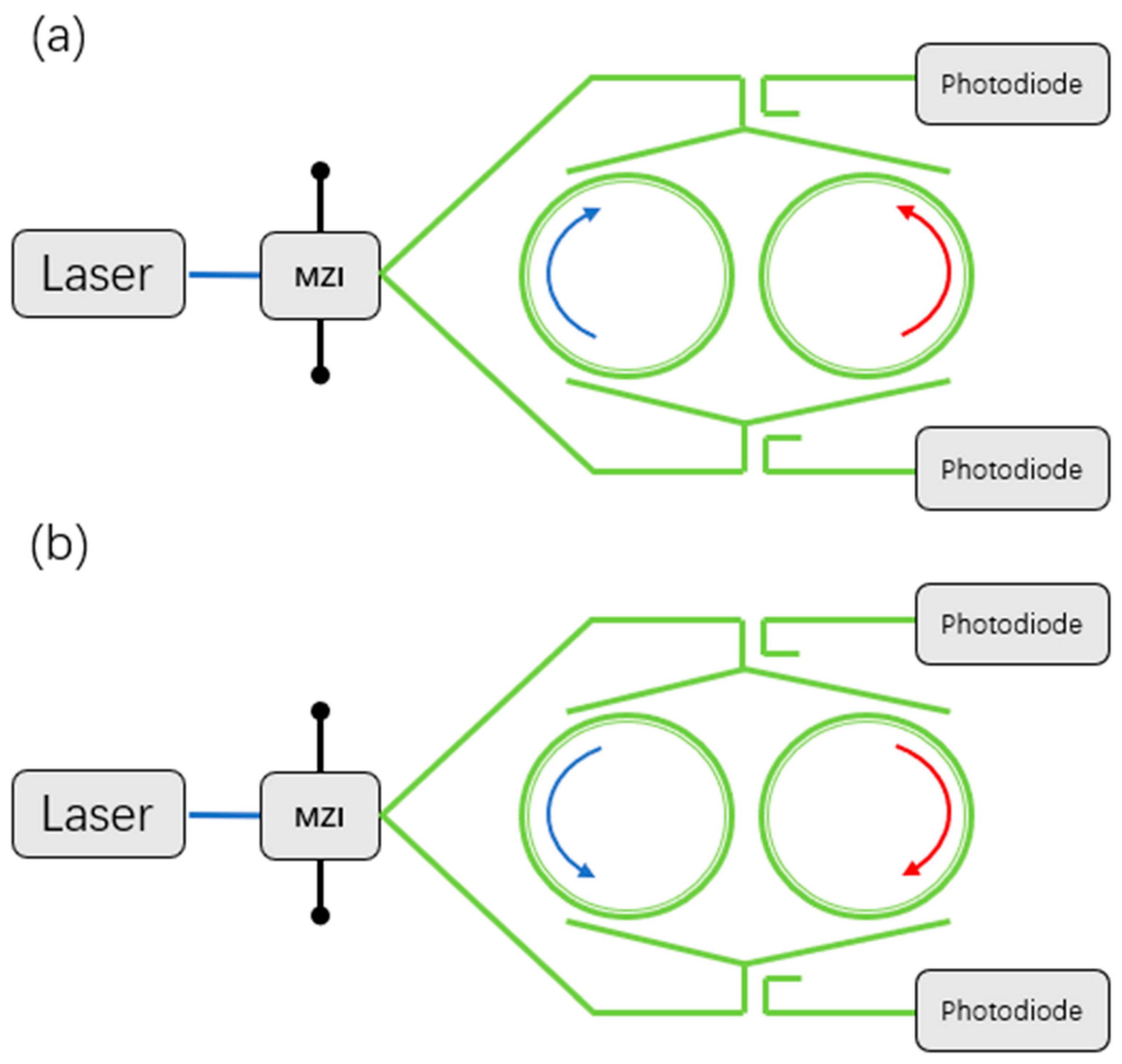
2.2. New Architectures of Ring Resonators for MOGs

In this section, new architectures of ring resonators for MOGs are reviewed. The rotation-induced superstructure in slow-light waveguides with mode degeneracy is investigated in [42]. The mode degeneracy on the characteristics of rotating WRR structure is studied. Using fiber Bragg grating ring resonators (FBGRR) for angular velocity sensing is proposed in [43]. On the bias of the fiber Bragg grating model under rotation conditions, the spectral response of FBGRR and π-shift FBGRR is evaluated, confirming that the Sagnac effect manifests itself with a special shift of the eigen-solutions. Multiple-ring resonators are reviewed in this section. Compared to conventional WRRs, multiple-ring resonators can achieve higher Q factors to enhance the sensitivity of MOGs. In this section, the double-ring resonators and multiple-ring resonators are mainly reviewed.

2.2.1. Double-Ring Resonators for MOGs

An MOG with reciprocal sensitivity enhancement is proposed in [44]. Reciprocal sensitivity enhancement offers an architecture that greatly reduces all sources of noise. It is achieved by the temporal separation between the CW and CCW beams and using high-frequency optical switching to cancel the thermal fluctuations. The system architecture is shown in Figure 5.
By introducing the reciprocity enhancement structure, the thermal fluctuations are negligible. The sensitivity improves 100 times where the switching frequency is set to 10 MHz compared to 20 kHz.
A double-ring resonator optical gyroscope is proposed in [45]. The two rings are not sided by side but through a 3 × 3 coupler. The coupler splits three ways and couples into two rings and the output port. The structure is shown in Figure 6.
If R1 ≠ R2, the frequency shapeshifts and its shape changes slightly, by launching laser light into the structure at a frequency that coincides with the steepest slope of the transmission spectrum. The coupling constant and the length mismatch affect the sensitivity most. In conclusion, for any value of the length mismatch, there is a coupling constant that maximizes the sensitivity.

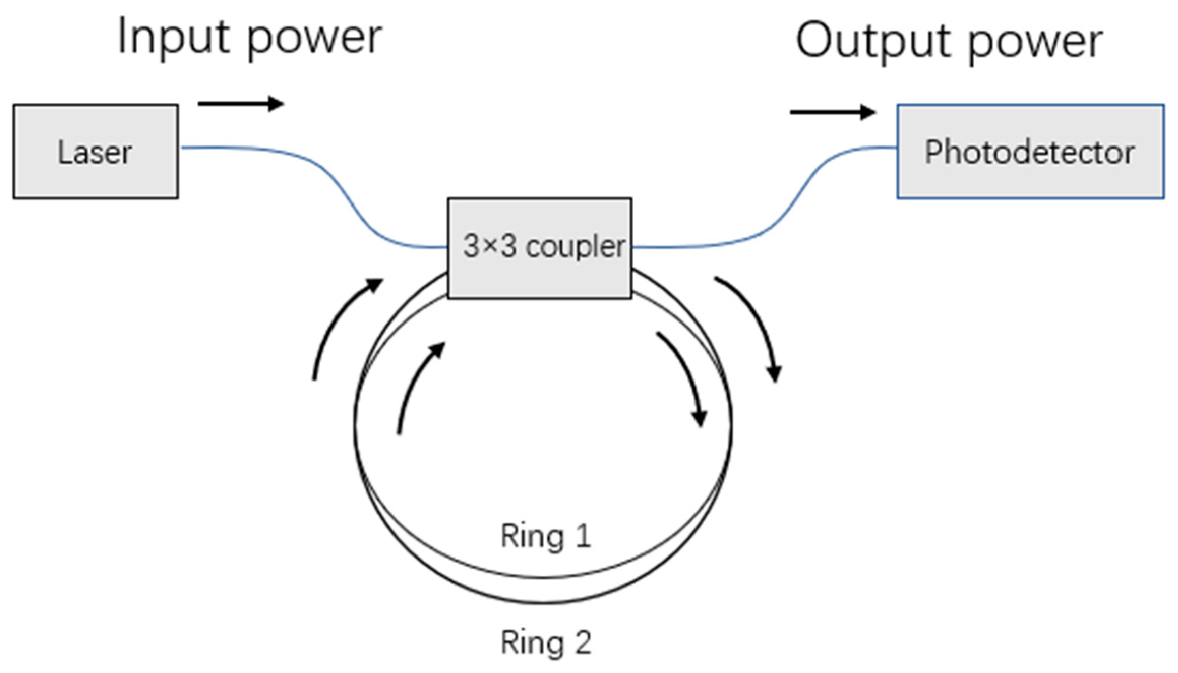
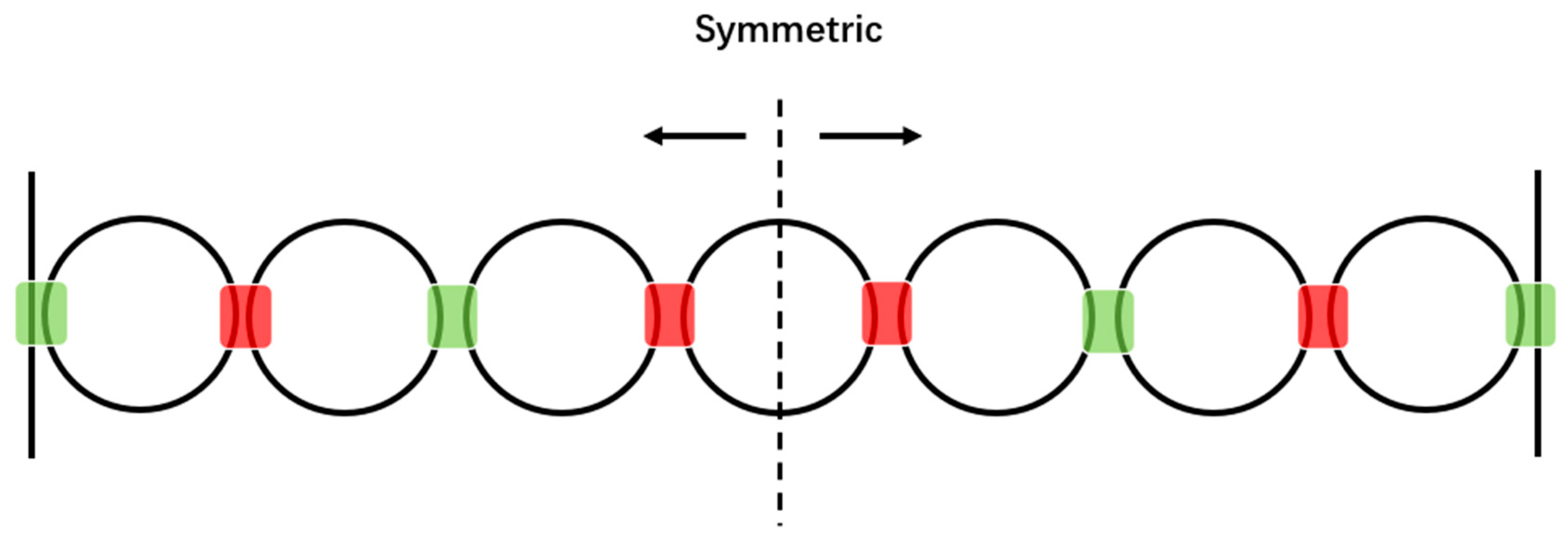
2.2.2. Multiple Ring Resonators for MOGs

A gyroscope based on the periodically modulated coupling of ring resonators is proposed in [46]. It consists of a linear array of WRRs coupled via evanescent waves with the shot-noise-limited rotation sensitivities on the order of 0.001 deg/h. To enhance the sensitivity of MOGs, they periodically modulate the evanescent coupling constant between resonators between a weak and strong coupling. The schematic diagram of the modulation scheme is shown in Figure 7.
By introducing a different coupling constant, the resonance is much narrow than a uniform coupled ring resonators having a much large number of resonators.

2.3. WRRs Candidates for MOGs

We have mentioned that the WRRs are the key elements in MOGs. Some material systems for integrated optical Kerr frequency combs are reviewed in [47]. The WRR varies in both cavity geometry and cavity materials. In this section, WRRs that have not been used in MOGs are reviewed, including silicon nitride (Si3N4) WRR, lithium niobate (LN) WRR, CaF2 WRR, magnesium fluoride (MgF2) WRR, and titanium oxide (TiO2) 3D WRRs. These WRRs have better performance, i.e., lower loss and higher Q factor. Fabrication details of WRRs are reviewed in this section.

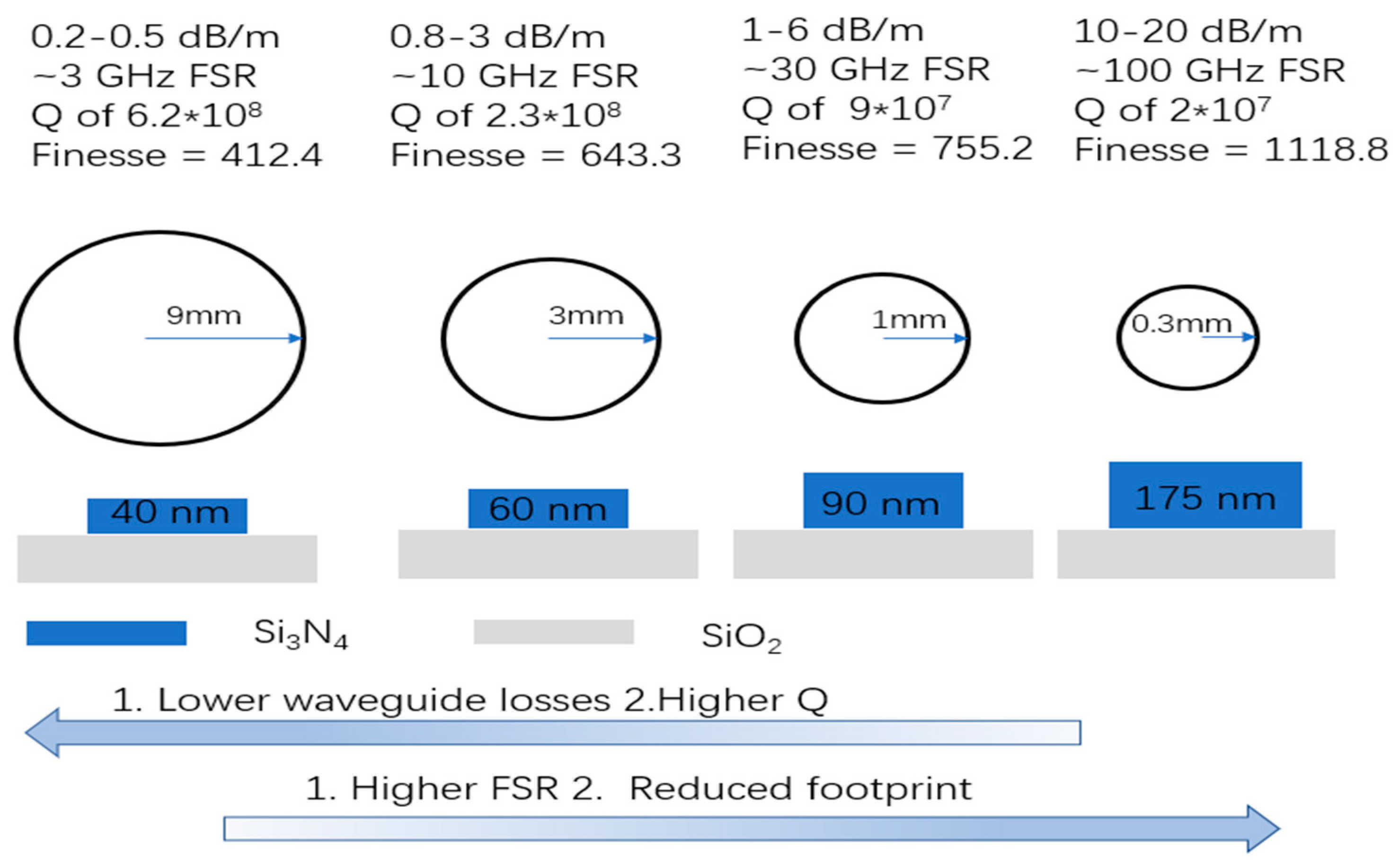
2.3.1. Silicon Nitride Waveguide Resonant Ring

Si3N4-based integrated optics have benefited from tremendous advances in fabrication technology and physical understanding of the optical phenomena involved [24,48,49]. Si3N4 is a trade-off to realize circuits and functions integration which require an ultra-low loss waveguide while balancing the loss and the footprint.
Fabrication of an Si3N4 waveguide with smooth sidewalls and tight confinement with record-low propagation losses is proposed in [50]. It is achieved by combining the photonic Damascene process with a novel reflow process, which reduces etching roughness, while sufficiently preserving dimensional accuracy. Instead of etching the waveguide pattern into a highly stressed, micrometer-thick Si3N4 film, the latter is deposited onto a preform structure with recesses that form the waveguide pattern. By combining the Damascus process with a reflow process, the roughness of etching is reduced and the accuracy of etching is increased. The process improvements with introduced preform reflow steps are shown in Figure 8.
By using the improved process, the Si3N4 resonant ring is fabricated with a Q factor of 1.2 × 10⁷ in [51].
However, the method using the Damascus reflow process results in intrinsically severe film thickness inhomogeneity on the wafer since it involves a chemical mechanical polishing (CMP) step for the removal of silicon nitride after filling the pre-formed reflux of etched silica. In fact, in this Damascus method, the CMP involves a thickness reduction of several hundred nanometers, so the difference caused by CMP is much greater compared to the typical uniformity of low-pressure chemical vapor deposition. The preformed reflow technique for smoothing silica pre-grooved sidewalls systematically introduces strong vertical inhomogeneity in the range of waveguide widths of tens or even hundreds of nanometers [52].
Another fabrication method is proposed in [53]. In this work, they report the fabrication and linear characterization of ultra-low loss, tightly bound Si3N4 waveguides with attenuation coefficients approaching ~3 dB/m. Multi-step chemical-physical annealing, fluorocarbon etching, and proper multilayer encapsulation show good capabilities when thicker films have to be deposited for many applications. The schematics of the twist-and-grow and multistep chemical-physical annealing process are shown in Figure 9.
The fabrication process starts with 3-μm-thick wet oxidation of a 200-mm diameter silicon wafer. It is followed by a twist-and-grow deposition of Si3N4 films until matching the desired thickness. After plasma patterning, the waveguide is well shaped, as shown in Figure 9d. The wafer has a bow of 230 μm due to the tensile stress of Si3N4 film. It can be managed by a selective removal of Si3N4 film remaining on the wafer backside after pattering on the front side. After multistep annealing and encapsulation, an Si3N4 ring resonator with the Q factor approaching 107 is fabricated.
Large-area high Q Si3N4 WRRs are fabricated in [54]. Increasing the area of WRRs benefits to a higher Q factor. The characteristic is shown in Figure 10.
A 40 nm core waveguide bending at a radius of 9 mm has a simulated TE bend loss of 0.001 dB/m, whereas the simulated TM bend loss is greater than 1000 dB/m. The waveguide has been demonstrated to have a polarization extinction ratio as high as 75 dB. A WRR with a Q factor reaching 6.2 × 10⁷ is fabricated which has a radius of 9 mm. Other WRRs with different core thickness and radius are fabricated. The performance can be optimized by using different WRRs.

2.3.2. Lithium Niobate Waveguide Ring Resonator

LN is a material with a wide range of applications in optical and microwave technologies owing to unique properties, including large second-order nonlinear susceptibility, large piezoelectric response, a wide optical transparency window, and high refractive index [55]. LN is a suitable material used in modulators due to its large second-order nonlinear susceptibility and large piezoelectric response, for which it can be used in monolithic integrated optical gyros so that it is easy to integrate an LN WRR with an LN modulator. The hybrid approach integrates easy-to-etch materials with LN films to direct light with relatively low propagation losses (0.3 dB/cm) [56].
All-pass micro WRRs are fabricated monolithically in Z-cut lithium niobate on insulator (LNOI) by using low-loss, high-index contrast, and single-mode C-band waveguides in [57]. The free spectral range (FSR) of the resonator is greater than 5 nm. The bending loss of TE mode significantly limits the Q factor of the WRR with a smaller radius. The Q factor can significantly increase with the ring radius increasing.
An ultra-low loss monolithic integrated LN photonic platform consisting of dry-etched subwavelength waveguides with extracted propagation losses as low as 2.7 dB/m and micro resonators with Q factor up to 107 is proposed in [58]. The devices are fabricated using a 600-nm thick X-cut LN film on a silicon substrate with 2-μm thick SiO2 films. Electron beam lithography is used to define the pattern. The pattern is then transferred to the LN film using plasma reactive ion etching. The LN is etched using Ar plasma, during which the plasma power and chamber conditions are adjusted to minimize surface re-deposition of the removed LN and other contaminants in the chamber. After cleaning and removing the mask, 1.5 μm SiO2 cladding layer is deposited using plasma-enhanced chemical vapor deposition to cover the devices.
Measurements show that the primary loss is from the sidewall. Since the LN device layer is on top of the standard silicon base, it can be integrated with other optics, with the expectation that it will be exploited on a monolithic integrated gyroscope.

2.3.3. CaF2 Waveguide Ring Resonator

Owing to high purity and low material losses, CaF2 WRR can make high Q resonators. CaF2 WRR has been used in MOGs [29], which shows the feasibility of its utilization to fabricate high precision MOGs. Another CaF2 WRR is fabricated in [59]. To improve the Q factor of the resonator, a thermal annealing method is used. The resonator is placed in a dry, argon-filled quartz glass tube mounted in a horizontal tube furnace. The temperature of the wick is raised linearly to 650 °C in approximately 3 h and cooled over 3 h. The resonator is polished and the process is repeated several times. The Q factor of the resonator can be improved by 5–6 times and the backscattering of light can be reduced by an order of magnitude.
In [32], the fabrication and packaging for high-Q CaF2 WRR is proposed. By developing the fine polishing method with abrasive particles based on a diamond turning and polishing apparatus, the rim of the WRR is characterized by less than 3 nm surface roughness. The disk rim is reshaped, eventually, to a V-shape, which makes the modified mode more concentrated and decreases the contact area.
The diameter of the WRR is 10.5 mm and the Q factor reaches 108. To improve the coupling efficiency, a packaged structure is used with the dimensions of 146 mm × 102 mm × 24 mm. After packing, the WRR is easy to portable and integrative, which shows its ability to be used in MOGs.

2.3.4. Magnesium Fluoride Waveguide Ring Resonator

MgF2 is also an excellent material for making WGM; however, it is difficult to make a resonant cavity on a single piece due to the poor compatibility of the manufacturing process. In [60], the first coupling of a compact waveguide to an MgF2 resonant ring on a silicon nitride substrate is achieved. This prism-waveguide coupler laterally couples light into and out of the resonator with 1 dB loss and the Q factor reaches 1.9 × 10⁹. The MgF2 resonant ring is mechanically shaped at a specific crystal cut. The control of the surface quality is achieved when no Rayleigh scattering in the resonator is observed. The waveguide planar circuits are shaped into a rectangular die to facilitate coupling the resonator in a compact platform.

2.3.5. Titanium Dioxide Waveguide Ring Resonator

A 3D vertical optical ring resonator fully integrated with nanophotonic waveguides is proposed in [25]. Vertical roll-up microcavity (VRUM) is a novel form of the ring resonator. The integration of WRR on multiple waveguides allowing for parallel and multi-routing through a single microcavity on the chip is demonstrated. The Si waveguides are fabricated on SiO2 and are prepared to roll up 2D differentially strained TiO2 nanomembranes into a 3D microtube. A 1-μm thick photoresist as a sacrificial layer is spin-coated onto the nanochip. Standard optical photolithography is employed to fabricate a U-shaped photoresist pattern for VRUM preparation. Strained TiO2 membranes are deposited by electron beam evaporation. To generate different strains in the membranes, the deposition is carried out at different rates. The photoresist is dissolved, causing the left-to-right roll-up of the TiO2 membrane to release built-in strain. The prepared VRUM has a diameter of 16 μm, a length of 180 μm, and four windings, resulting in a wall thickness of 460 nm. The Q factor is calculated as 310 due to the coupling loss. The VRUM can be used as several vertical ring resonators independently at several positions along the tube axis, while this is impossible for 2D planar WRRs which can be used in a complex platform.

2.4. Summary

In this section, we summarize the WRRs that have already been used in most advanced MOGs in Table 1 and the WRRs that have not been used in MOGs in Table 2. The WRRs in Table 2 have better performances than those in Table 1. The sensitivity in Table 2 is calculated consuming the WRRs are employed in MOGs, from which we can see that the performances of the MOGs are better.
With the prototype MOGs that have been reviewed before, basic features of them are reviewed in Table 1. Silica MOG has the most outstanding performance, especially regarding sensitivity. Hybrid integration technology can be used to further improve the integration to solve the problem that active devices cannot be made by silica. Both InP MOG and polymer MOG have achieved monolithic integration. The high propagation loss of waveguide leads to a lower Q factor of WRR, which limits the improvement of sensitivity [28,30]. CaF2 MOG has been integrated on an optical micro-bench. The volume of the resonator mode should be increased to improve sensitivity [29].
The high-Q WRRs which have not been used in MOGs are summarized in Table 2. By considering Equation (1) and assuming the measurement bandwidth B = 1 Hz, the optical power of photodetector Ppd = 20 mW, and the photodetector efficiency ηpd = 0.9, the shot-noise-limited sensitivity of MOGs is calculated. Compared to Table 1, MOGs perform better in sensitivity if higher Q WRRs are applied.
By utilizing a high aspect ratio silicon nitride waveguide, the propagation loss can be reduced to 0.2 dB/m. The single polarization mode operation is achieved, which can significantly reduce the polarization fluctuation noise [54]. Si3N4 WRRs enable more complex integration with a wide variety of low-loss photonic components, such as active layers with hybrid silicon, as well as integration with silicon photonics and III/V photonic circuits [61]. For these reasons, we think the Si3N4 WRRs have the most integration flexibility and feasibility.
LN has unique properties, including large second-order nonlinear susceptibility and a large piezoelectric response. By using bonding technology, LN WRRs can easily integrate with other devices [62]. Compared to Si3N4 WRRs, the propagation loss of LN WRRs is much higher—especially the bending loss. There is still lot of work to do to employ LN WRRs in MOGs.
CaF2 and MgF2 WRRs both have the highest Q factor. They also have fewer non-reciprocal sources. However, material incompatibility (e.g., low refractive index) and the incompatible fabrication process between traditional photonic platforms and the mechanically polished crystalline resonators make it hard to integrate these with other devices [36]. Compared to other materials, CaF2 and MgF2 WRRs have the most difficulties in integration.
The 3D vertical coupled ring resonator has achieved resonator filtering of optical signals at telecom wavelengths and it shows huge potential in integrating complex integration. Compared to Si3N4 conventional WRRs, Q factors need to be improved. We expect that TiO2 WRRs will be used in MOGs if the WRR area increases and the Q factors are improved.

3. Conclusions

Recently developed high-Q WRRs have been reviewed in this paper. Silica WRR, InP WRR, CaF2 WRR, and polymer WRR have been used in MOGs. With a Q factor over 1.46 × 10⁷, the sensitivity can reach 3.74 deg/h. The gyros perform better when the Q factor of the resonator is larger, and although Si3N4 WRRs have not been used in any MOGs, they show huge potentiality due to the low-loss characteristic and their compatibility with CMOS fabrication technology. The Q factor of the candidate WRRs are much higher than those used in MOGs, which makes the improvement of MOGs foreseeable.
We expect to find a suitable material to make a high-Q WRR in order to improve the performance of MOGs in the next few years. Better performance and smaller-scale promise micro-optical gyroscopes a variety of applications in navigation systems.

Author Contributions

Writing—original draft preparation, Z.F.; writing—review and editing, Y.H. and Z.L.; project administration, F.Y.; funding acquisition, W.Y. and W.H. All authors have read and agreed to the published version of the manuscript.

Funding

This research was funded by the National Key Research and Development Program of China, grant number 2016YFA0200503, and the National Nature Science Foundation of China, grant number 61971395.

Conflicts of Interest

The authors declare no conflict of interest.

References

  1. Ezekiel, S.; Balsamo, S. Passive ring resonator laser gyroscope. Appl. Phys. Lett. 1977, 30, 478–480. [Google Scholar] [CrossRef]
  2. Venediktov, V.Y.; Filatov, Y.V.; Shalymov, E.V. Passive Ring Resonator Micro-Optical Gyroscopes. Quantum Electron. 2016, 46, 437–446. [Google Scholar] [CrossRef]
  3. Suzuki, K.; Takiguchi, K.; Hotate, K. Monolithically Integrated Resonator Microoptic Gyro on Silica Planar Lightwave Circuit. J. Lightwave Tech. 2000, 18, 66–72. [Google Scholar] [CrossRef]
  4. Chow, W.W.; Gea-Banacloche, J.; Pedrotti, L.M.; Sanders, V.E.; Schleich, W.; Scully, M.O. The Ring Laser Gyro. Rev. Mod. Phys. 1985, 57, 61. [Google Scholar] [CrossRef]
  5. Huai-Yong, Y.; Chun-Xi, Z.; Li-Shuang, F.; Zhen, Z.; Ling-Fei, H. Sio2 Waveguide Resonator Used in an Integrated Optical Gyroscope. Chin. Phys. Lett. 2009, 26, 054210. [Google Scholar] [CrossRef]
  6. Ma, H.; He, Z.; Hotate, K. Reduction of Backscattering Induced Noise by Carrier Suppression in Waveguide-Type Optical Ring Resonator Gyro. J. Lightwave Tech. 2011, 29, 85–90. [Google Scholar] [CrossRef]
  7. Huilan Liu, L.F.; Jiao, Z.; Li, R. Polarization Noise and Reduction Technology in Micro Optical Gyroscope. In Proceedings of the 2011 6th IEEE International Conference on Nano/Micro Engineered and Molecular Systems, Kaohsiung, Taiwan, 20–23 February 2011. [Google Scholar]
  8. Li, X.; Zhang, J.; Ma, H.; Jin, Z. Test and Analysis of the Optical Kerr-Effect in Resonant Micro-Optic Gyros. IEEE Photon. J. 2014, 6, 1–7. [Google Scholar]
  9. Cutler, C.C.; Newton, S.A.; Shaw, H.J. Limitation of Rotation Sensing by Scattering. Opt. Lett. 1980, 5, 488–490. [Google Scholar] [CrossRef]
  10. Hsiao, H.-K.; Winick, K. Planar Glass Waveguide Ring Resonators with Gain. Opt. Express 2007, 15, 17783–17797. [Google Scholar] [CrossRef]
  11. Hotate, K.; Higashiguchi, M. Eigenstate of Polarization in a Fiber Ring Resonator and its Effect in an Optical Passive Ring-Resonator Gyro. Appl. Opt. 1986, 25, 2606–2612. [Google Scholar]
  12. Zhi, Y.; Feng, L.; Lei, M.; Wang, K. Low-Delay, High-Bandwidth Frequency-Locking Loop Of Resonator Integrated Optic Gyro With Triangular Phase Modulation. Appl. Opt. 2013, 52, 8024–8031. [Google Scholar] [CrossRef]
  13. Strandjord, L.K.; Sanders, G.A. Effects of Imperfect Serrodyne Phase Modulation in Resonator Fiber Optic Gyroscopes. In Proceedings of the SPIE’s 1994 International Symposium on Optics, Imaging, and Instrumentation, San Diego, CA, USA, 24–29 July 1994; International Society for Optics and Photonics: Bellingham, WA, USA. [Google Scholar]
  14. Ma, H.; Zhang, X.; Jin, Z.; Ding, C. Waveguide-Type O Passive Ring Resonator Gyro Using Phase Modulation Spectroscopy Technique. Opt. Eng. 2006, 45, 080506-080506-3. [Google Scholar] [CrossRef] [Green Version]
  15. Ying, D.; Ma, H.; Jin, Z. Resonator Fiber Optic Gyro Using the Triangle Wave Phase Modulation Technique. Opt. Commun. 2008, 281, 580–586. [Google Scholar] [CrossRef]
  16. Mao, H.; Ma, H.; Jin, Z. Resonator Micro-Optic Gyroscope Based on the Double Phase Modulation Technique. In Proceedings of the Conference on Lasers and Electro.-Optics, San Jose, CA, USA, 16–21 May 2010; Optical Society of America: Washington, DC, USA. [Google Scholar]
  17. Lei, M.; Feng, L.; Zhi, Y. Sensitivity Improvement of Resonator Integrated Optic Gyroscope by Double-Electrode Phase Modulation. Appl. Opt. 2013, 52, 7214–7219. [Google Scholar] [CrossRef] [PubMed]
  18. Zhi, Y.; Feng, L.; Wang, J.; Tang, Y. Reduction of Backscattering Noise in a Resonator Integrated Optic Gyro by Double Triangular Phase Modulation. Appl. Opt. 2015, 54, 114–122. [Google Scholar] [CrossRef] [PubMed]
  19. Feng, L.S.; Lei, M.; Liu, H.; Zhi, Y.; Wang, J. Suppression of Backreflection Noise in a Resonator Integrated Optic Gyro by Hybrid Phase-Modulation Technology. Appl. Opt. 2013, 52, 1668–1675. [Google Scholar] [CrossRef]
  20. Ma, H.; Zhang, J.; Wang, L.; Jin, Z. Double Closed-Loop Resonant Micro Optic Gyro Using Hybrid Digital Phase Modulation. Opt. Express 2015, 23, 15088–15097. [Google Scholar] [CrossRef]
  21. Guillén-Torres, M.Á.; Cretu, E.; Jaeger, N.A.; Chrostowski, L. Ring Resonator Optical Gyroscopes—Parameter Optimization and Robustness Analysis. J. Lightwave Tech. 2012, 30, 1802–1817. [Google Scholar] [CrossRef]
  22. Zhang, J.; Li, H.; Ma, H.; Jin, Z. High. Finesse Silica Waveguide Ring Resonators for Resonant Micro-Optic Gyroscopes. In Proceedings of the 25th International Conference on Optical Fiber Sensors, Jeju, South Korea, 24–28 April 2017; International Society for Optics and Photonics: Bellingham, WA, USA, 2017. [Google Scholar]
  23. Spencer, D.T.; Bauters, J.F.; Heck, M.J.; Bowers, J.E. Integrated Waveguide Coupled Si_3n_4 Resonators in the Ultrahigh-Q Regime. Optica 2014, 1, 153. [Google Scholar] [CrossRef] [Green Version]
  24. Tian, H.; Liu, J.; Dong, B.; Skehan, J.C.; Zervas, M.; Kippenberg, T.J.; Bhave, S.A. Hybrid. Integrated Photonics Using Bulk Acoustic Resonators. Nat. Commun. 2020, 11, 3073. [Google Scholar] [CrossRef]
  25. Madani, A.; Kleinert, M.; Stolarek, D.; Zimmermann, L.; Ma, L.; Schmidt, O.G. Vertical Optical Ring Resonators Fully Integrated With Nanophotonic Waveguides on Silicon-on-Insulator Substrates. Opt. Lett. 2015, 40, 3826–3829. [Google Scholar] [CrossRef] [PubMed] [Green Version]
  26. Ciminelli, C.; Dell’Olio, F.; Campanella, C.E.; Armenise, M.N. Photonic Technologies for Angular Velocity Sensing. Adv. Opt. Photon. 2010, 2, 370–404. [Google Scholar] [CrossRef]
  27. Zhang, J.; Ma, H.; Li, H.; Jin, Z. Single-Polarization Fiber-Pigtailed High-Finesse Silica Waveguide Ring Resonator for a Resonant Micro-Optic Gyroscope. Opt. Lett. 2017, 42, 3658–3661. [Google Scholar] [CrossRef]
  28. Ciminelli, C.; D’Agostino, D.; Carnicella, G.; Dell’Olio, F.; Conteduca, D.; Ambrosius, H.P.; Smit, M.K.; Armenise, M.N. A High.-InP Resonant Angular Velocity Sensor for a Monolithically Integrated Optical Gyroscope. Photon. J. IEEE 2016, 8, 1–18. [Google Scholar] [CrossRef]
  29. Liang, W.; Ilchenko, V.S.; Savchenkov, A.A.; Dale, E.; Eliyahu, D.; Matsko, A.B.; Maleki, L. Resonant Microphotonic Gyroscope. Optica 2017, 4, 114–117. [Google Scholar] [CrossRef]
  30. Qian, G.; Zhang, T.; Zhang, L.J.; Tang, J.; Zhang, X.Y.; Lu, Y.; Wan, F.H. Demonstrations of Centimeter-Scale Polymer Resonator for Resonant Integrated Optical Gyroscope. Sens. Actuators Phys. 2016, 237, 29–34. [Google Scholar] [CrossRef]
  31. D’Agostino, D.; Carnicella, G.; Ciminelli, C.; Thijs, P.; Veldhoven, P.J.; Ambrosius, H.; Smit, M. Low-Loss Passive Waveguides in a Generic Inp Foundry Process Via Local Diffusion of Zinc. Opt. Express 2015, 23, 25143–25157. [Google Scholar] [CrossRef]
  32. Wang, M.; Yang, Y.; Meng, L.; Jin, X.; Dong, Y.; Zhang, L.; Wang, K. Fabrication and Packaging for High-Q Caf2 Crystalline Resonators with Modal Modification. Chin. Opt. Lett. 2019, 17, 111401. [Google Scholar] [CrossRef]
  33. Grudinin, I.S.; Matsko, A.B.; Maleki, L. On the Fundamental Limits of Q Factor of Crystalline Dielectric Resonators. Opt. Express 2007, 15, 3390–3395. [Google Scholar] [CrossRef]
  34. Matsko, A.B.; Savchenkov, A.A.; Ilchenko, V.S.; Maleki, L. Optical Gyroscope with Whispering Gallery Mode Optical Cavities. Opt. Commun. 2004, 233, 107–112. [Google Scholar] [CrossRef]
  35. Lefèvre, H.C. Fundamentals of the Interferometric Fiber-Optic Gyroscope. Opt. Rev. 1997, 4, A20–A27. [Google Scholar]
  36. Matsko, A.B.; Savchenkov, A.A.; Strekalov, D.; Ilchenko, V.S.; Yu, N.; Maleki, L. Fabrication, Characterization and Applications of Crystalline Whispering Gallery Mode Resonators. In Proceedings of the International Conference on Transparent Optical Networks, Rome, Italy, 1–5 July 2007; pp. 50–54. [Google Scholar]
  37. Li, R.-Z.; Zhang, T.; Yu, Y.; Jiang, Y.J.; Zhang, X.Y.; Wang, L.D. Flexible Multilayer Substrate Based Optical Waveguides: Applications to Optical Sensing. Sens. Actuators Phys. 2014, 209, 57–61. [Google Scholar] [CrossRef]
  38. Tazawa, H.; Kuo, Y.H.; Dunayevskiy, I.; Luo, J.; Jen, A.K.Y.; Fetterman, H.R.; Steier, W.H. Ring Resonator-Based Electrooptic Polymer Traveling-Wave Modulator. J. Lightwave Tech. 2006, 24, 3514–3519. [Google Scholar] [CrossRef]
  39. Ren, J.; Wang, L.; Han, X.; Cheng, J.; Lv, H.; Wang, J.; Jian, X.; Zhao, M.; Jia, L. Organic Silicone Sol-Gel Polymer as a Noncovalent Carrier of Receptor Proteins for Label-Free Optical Biosensor Application. ACS Appl. Mater. Interfaces 2013, 5, 386–394. [Google Scholar] [CrossRef] [PubMed]
  40. Rabiei, P.; Steier, W.H. Tunable Polymer Double Micro-Ring Filters. IEEE Photon. Tech. Lett. 2003, 15, 1255–1257. [Google Scholar] [CrossRef]
  41. Sanghadasa, M.; Ashley, P.R.; Lindsay, G.A.; Bramson, M.D.; Tawney, J. Backscatter Compensation in IFOG Based Inertial Measurement Units With Polymer Phase Modulators. J. Lightwave Tech. 2009, 27, 806–813. [Google Scholar]
  42. Steinberg, B.Z.; Scheuer, J.; Boag, A. Rotation-Induced Superstructure in Slow-Light Waveguides With Mode-Degeneracy: Optical Gyroscopes with Exponential Sensitivity. J. Opt. Soc. Am. B 2007, 24, 1216–1224. [Google Scholar] [CrossRef]
  43. Campanella, C.E.; De Leonardis, F.; Passaro, V.M. Fiber Bragg Grating Ring Resonators Under Rotation for Angular Velocity Sensing. Appl. Opt. 2015, 54, 4789–4796. [Google Scholar] [CrossRef]
  44. Khial, P.P.; White, A.D.; Hajimiri, A. Nanophotonic Optical Gyroscope with Reciprocal Sensitivity Enhancement. Nat. Photon. 2018, 12, 671–675. [Google Scholar] [CrossRef] [Green Version]
  45. Grant, M.J.; Digonnet, M.J.F. Double-Ring Resonator Optical Gyroscopes. J. Lightwave Tech. 2018, 36, 2708–2715. [Google Scholar] [CrossRef]
  46. Sorrentino, C.; Toland, J.R. Ultra-Sensitive Chip Scale Sagnac Gyroscope Based on Periodically Modulated Coupling of a Coupled Resonator Optical Waveguide. Opt. Express 2012, 20, 354–363. [Google Scholar] [CrossRef] [PubMed]
  47. Kovach, A.; Chen, D.; He, J.; Choi, H.; Dogan, A.H.; Ghasemkhani, M.; Armani, A.M. Emerging Material Systems for Integrated Optical Kerr Frequency Combs. Adv. Opt. Photon. 2020, 12, 135–222. [Google Scholar] [CrossRef] [Green Version]
  48. Sacher, W.D.; Huang, Y.; Lo, G.Q.; Poon, J.K. Multilayer Silicon Nitride-on-Silicon Integrated Photonic Platforms and Devices. J. Lightwave Tech. 2015, 33, 901–910. [Google Scholar] [CrossRef]
  49. Anderson, M.H.; Lihachev, G.; Weng, W.; Liu, J.; Kippenberg, T.J. Zero-Dispersion Kerr Solitons In Optical Microresonators. arXiv 2020, arXiv:2007.14507. [Google Scholar]
  50. Pfeiffer, M.H.; Kordts, A.; Brasch, V.; Zervas, M.; Geiselmann, M.; Jost, J.D.; Kippenberg, T.J. Photonic Damascene Process for Integrated High-Q Microresonator Based Nonlinear Photonics. Optica 2016, 3, 20–25. [Google Scholar] [CrossRef]
  51. Pfeiffer, M.H.; Kordts, A.; Brasch, V.; Zervas, M.; Geiselmann, M.; Jost, J.D.; Kippenberg, T.J. Ultra-Smooth Silicon Nitride Waveguides Based on the Damascene Reflow Process: Fabrication and Loss Origins. Optica 2018, 5, 20–25. [Google Scholar] [CrossRef]
  52. Pfeiffer, M.H.P.; Herkommer, C.; Liu, J.; Morais, T.; Zervas, M.; Geiselmann, M.; Kippenberg, T.J. Photonic Damascene Process. for Low-Loss, High.-Confinement Silicon Nitride Waveguides. IEEE J. Sel. Top. Quantum Electron. 2018, 24, 1–11. [Google Scholar] [CrossRef]
  53. El Dirani, H.; Youssef, L.; Petit-Etienne, C.; Kerdiles, S.; Grosse, P.; Monat, C.; Sciancalepore, C. Ultralow-Loss Tightly Confining Si3n4 Waveguides and High-Q Microresonators. Opt. Express 2019, 27, 30726–30740. [Google Scholar] [CrossRef]
  54. Huffman, T.A.; Brodnik, G.M.; Pinho, C.; Gundavarapu, S.; Baney, D.; Blumenthal, D.J. Integrated Resonators in an Ultralow Loss Si3N4/SiO2 Platform for Multifunction Applications. IEEE J. Sel. Top. Quantum Electron. 2018, 24, 1–9. [Google Scholar] [CrossRef]
  55. Ferraro, P.; Grilli, S.; De Natale, P. Ferroelectric Crystals for Photonic Applications; Springer: Cham, Switzerland, 2008. [Google Scholar]
  56. Chang, L.; Li, Y.; Volet, N.; Wang, L.; Peters, J.; Bowers, J.E. Thin Film Wavelength Converters for Photonic Integrated Circuits. Optica 2016, 3, 531–535. [Google Scholar] [CrossRef]
  57. Krasnokutska, I.; Tambasco, J.-L.J.; Peruzzo, A. Tunable Large Free Spectral Range Microring Resonators in Lithium Niobate on Insulator. Sci. Rep. 2019, 9, 1–7. [Google Scholar] [CrossRef] [PubMed] [Green Version]
  58. Zhang, M.; Wang, C.; Cheng, R.; Shams-Ansari, A.; Lončar, M. Monolithic Ultra-High-Q Lithium Niobate Microring Resonator. Optica 2017, 4, 1536–1537. [Google Scholar] [CrossRef]
  59. Savchenkov, A.A.; Liang, W.; Ilchenko, V.; Matsko, A.; Maleki, L. Crystalline Waveguides for Optical Gyroscopes. IEEE J. Sel. Top. Quantum Electron. 2018, 24, 1–11. [Google Scholar] [CrossRef]
  60. Liu, G.; Ilchenko, V.S.; Su, T.; Ling, Y.-C.; Feng, S.; Shang, K.; Zhang, Y.; Liang, W.; Savchenkov, A.A.; Matsko, A.B.; et al. Low-Loss Prism-Waveguide Optical Coupling for Ultrahigh-Q Low-Index Monolithic Resonators. Optica 2018, 5, 219–226. [Google Scholar] [CrossRef]
  61. Piels, M.; Bauters, J.F.; Davenport, M.L.; Heck, M.J.; Bowers, J.E. Low-Loss Silicon Nitride AWG Demultiplexer Heterogeneously Integrated With Hybrid. III–V/Silicon Photodetectors. J. Lightwave Tech. 2014, 32, 817–823. [Google Scholar] [CrossRef]
  62. Weigel, P.O.; Savanier, M.; DeRose, C.T.; Pomerene, A.T.; Starbuck, A.L.; Lentine, A.L.; Mookherjea, S. Lightwave Circuits in Lithium Niobate through Hybrid. Waveguides with Silicon Photonics. Sci. Rep. 2016, 6, 22301. [Google Scholar] [CrossRef] [PubMed] [Green Version]
Figure 1. Schematics of the Sagnac effect. The black rings represent the waveguide ring resonators (WRRs). The left panel: the situation of zero rotation rate. The right panel: the WRR under Ω rotation rate. Difference between clockwise (CW) and counterclockwise (CCW) optical paths caused by the Sagnac effect is shown.
Photonics 07 00096 g001
Figure 2. System structure of passive micro-optical gyros (MOGs). PM is a phase modulator. PD is a photo detector. LIA is a lock-in Amplifier.
Photonics 07 00096 g002
Figure 3. Schematic diagram of a whispering gallery mode resonator (WGMR) gyroscope.
Photonics 07 00096 g003
Figure 4. The fabrication process of polymer-based waveguide ring resonator (WRR). (a) The core layer was spin-coated on the adhesive layer. (b) Al layer deposition and photoresist layer spin-coated on the core layer. (c) Photoresist layer patterning. (d) Double layers patterning (e) Core layer patterning. (f) Removing the mask. (g) Cladding and annealing.
Photonics 07 00096 g004
Figure 5. Reciprocal sensitivity enhancement architecture. By using a Mach–Zehnder interferometer (MZI), the ring resonators can be fed from two different directions, and the output toggles between two photodiodes.
Photonics 07 00096 g005
Figure 6. Double-ring resonator using a 3 × 3 coupler.
Photonics 07 00096 g006
Figure 7. The schematic diagram of the proposed modulation scheme for evanescent coupling. The green and red represent strong and weak coupling between resonators which alternates between weak (green) and strong (red) coupling or vice versa symmetrically about the center resonator.
Photonics 07 00096 g007
Figure 8. Schematic process flow of the photonic Damascene process. (a) Waveguide patterning. (b) Filler patterning. (c) Preform etching. (d) Preform reflow at 1250 ℃. (e) Si3N4 deposition. (f) Planarization. (g) Cladding and annealing.
Photonics 07 00096 g008
Figure 9. Schematics of the twist-and-grow and multistep chemical-physical annealing process for ultralow-loss tightly confining Si3N4 waveguides. (a) 3-μm thick wet oxidation of a 200-mm Si wafer is followed by a twist-and-grow deposition of Si3N4 films until matching the desired film thickness (800 nm). (b) Fluorocarbon-based dry etching and wafer bow compensation. (c) Multistep H2/O2/N2 in-situ annealing of patterned core Si3N4 waveguides. (d) Multistep encapsulation via a low-temperature silicon dioxide liner before high-density plasma silica layers encapsulation.
Photonics 07 00096 g009
Figure 10. Characteristic of WRRs with different thickness core and radius.
Photonics 07 00096 g010
Table 1. Basic features of WRRs already used in MOG prototypes.
GyrosQ factorDiameterBias Stability (deg/h)Sensitivity (deg/h)
Silica micro gyro [27]1.46 × 1072.5 cm0.0043.74
InP Micro gyro [28]6 × 1053 mmA few150
CaF2 Micro gyro [29]1 × 1097 mm3-
Polymer Micro gyro [30]1 × 1051 cm-324
Table 2. Basic features of high quality factor (Q) WRRs.
MaterialQ factorDiameterLossIntegrationSensitivity (deg/h)
Si3N4 [53]1 × 107220 μm3 dB/m▲▲▲-
Si3N4 [54]6.2 × 10818 mm0.2–0.5 dB/m▲▲▲0.03
LN [58]1 × 107180 μm>10 dB/m▲▲-
CaF2 [59]5 × 1093.8 mm-0.01
MgF2 [60]1.9 × 1092.66 mm3.8 dB0.05
TiO2 [25]31016 μm--
Publisher’s Note: MDPI stays neutral with regard to jurisdictional claims in published maps and institutional affiliations.

