Abstract
A silica resonator was demonstrated for random laser generation. The resonator consisted of a conventional microsphere fabricated in an optical fiber tip through electric arc discharge, and modifications to its geometry were carried out to create asymmetry inside the silica structure. The resulting Bunimovich stadium-like microsphere promotes multiple reflections with the boundaries, following the stochastic properties of dynamic billiards. The interference of the multiple scattered beams generates a random signal whose intensity was increased by sputter-coating the microstadium with a gold thin film. The random signal is amplified using an erbium-doped fiber amplifier (EDFA) in a ring cavity configuration with feedback, and lasing is identified as temporal and spectral random variations of the signal between consecutive measurements.
1. Introduction
Optical scattering has been considered undesirable for laser physics in the past, and measures were taken to make up for this phenomenon. However, for the past few decades, increasing attention is being addressed to introducing new applications and functionalities based on multiple scattering into new optical technologies, instead of merely avoiding the effect. Earlier, in 1967, Letokhov predicted the possibility of laser emission through a feedback mechanism based on multiple scattering of light [1].
The conventional laser mainly consists of a material responsible for amplifying light of a particular wavelength by means of stimulated emission, and an optical cavity for confining the gain medium [2]. When the total gain surpasses the optical losses, threshold is reached and lasing occurs. A random laser is a class of lasers without a well-defined cavity. Instead, light is confined in the gain medium through multiple scattering. This means that, while in conventional lasers the optical modes and their frequency are determined by the optical cavity, in random lasers the modes are determined, with a specific frequency and bandwidth, by the interference of multiple scattering [3]. When gain is applied, random modes will selectively lase in space and time, due to the modes’ competition for gain [4,5]. Random lasers present some advantages over other lasers, including low production costs and simple technical design [6,7]. Due to the fluctuations in their stochastic emission spectra, random lasers found applications such as in secure optical communications [8] and in random number generation [9]. Random lasers can be engineered to provide low spatial coherence, making them better candidates than conventional lasers for applications in speckle-free imaging and medical diagnosis [10,11,12]. Multiple scattering has been observed using a wide variety of disordered gain materials, including scattering powders [13], zinc oxide nanoparticles [14], microcavities with decoupled gain and scattering regions [5], cold atoms [15], and all-fiber gain media, such as D-shape cross section multimode fiber [16], Er-doped single-mode fibers with randomly distributed Bragg gratings [17], and organic nanofibers [18].
In all the above-mentioned cases, scattered light is amplified inducing the necessary feedback for random lasing. In the present work, the feedback mechanism leading to light trapping within the scattering medium is achieved with a modified silica microsphere in the tip of a single mode optical fiber. The modified microsphere closely resembles the Bunimovich stadium, which follows the stochastic properties of motion in billiards [19]. In a conventional microsphere on a fiber tip, most of the light reflected on the tip of the microsphere goes back to the core of the fiber after one roundtrip. Owing to the shape of a Bunimovich stadium (a rectangle with a semicircle on each side), light scattered in the boundary is kept trapped inside the microstadium, promoting multiple interferences, and contributing to an increase in the random component of the signal. Microlasers have been developed in semiconductors [20], dyes [21], and polymers [22], using 2D configurations based on Bunimovich stadium-like resonators. Such configurations include, for example, quasi-stadium [23,24], spiral [25], annular [26], and limaçon shapes [27], and other alternative designs, such as an isosceles triangle with rounded corners [28], and a circle connected to an isosceles trapezoid [29]. It was shown that, by tailoring the shape of stadium-like resonators, it was possible to optimize light confinement and achieve low laser threshold [30]. It was also shown that, although the major-to-minor axis ratio only slightly varies, the corresponding emission spectra drastically changes due to the different dynamics of rays trapped in each resonator. Other more complex geometries of stadium resonators, such as the single-nanowire [31] or micropillars with non-circular cross-sections [22], require microfabrication which can be an expensive and time-consuming process.
In this paper, we present a Bunimovich stadium-like resonator for random signal generation. Unlike the above-mentioned geometries, this microstadium is a simple all-fiber resonator in a 3D configuration. The fabrication of the resonator was a low-cost process, uniquely involving a conventional fusion splicer. A gold coating was deposited over the structure, and the spectra before and after the deposition were compared. Placing the structure in a cavity ring configuration with feedback, lasing was identified as pulses randomly distributed in wavelength.
2. Materials and Methods
Asymmetry was achieved by fabricating a non-spherical resonator—microstadium—by splicing together two conventional microspheres, each in the tip of a cleaved single mode fiber (SMF). The spherical microspheres were prepared with a Sumitomo Electronics (TYPE-71C) conventional fusion splicer in manual mode (Figure 1a). The two microspheres were spliced together by discharging multiple electric arcs (Figure 1c), then cleaving one of the SMF fibers (Figure 1d), and applying a final electric arc to uniformize the tip (Figure 1e). The real values of power discharge were unknown since the fusion splicer shows relative values only. For the fabrication of the two conventional microspheres and for their splicing, the following parameters were selected: relative power of +100, 0 s pre-fusion time, and 4 s fusion time (Figure 1a,c); for the last arc on the tip, the chosen parameters were: relative power of +100, 0 s pre-fusion time, and 2 s fusion time (Figure 1e). The microstadium used in this study has a shape similar to an ellipse or a Bunimovich stadium, with an approximate 411 μm major axis and a 306 μm minor axis (Figure 1f).
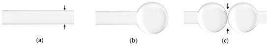
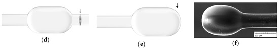
Figure 1.
Stadium resonator: (a–e) schematic of its fabrication; dark arrows represent electric arcs, while a light arrow represents a cleave; (f) scanning electron microscopy (SEM) imaging.
Following its fabrication, the microstadium was sputter-coated with a gold thin film. The Au layer works as a mirror, confining light inside the microstadium. Zemax OpticStudio software was used to model optical ray tracing inside the structure, both before and after the gold coating deposition (Figure 2). For the uncoated resonator, most light is transmitted outwards, while only approximately 4% is reflected back to the microstadium, mostly following a similar path as the incident cone of light (Figure 2a). The mirror coating introduces new light reflections, which travel different optical paths inside the silica structure. Therefore, the interference of the light coupled to the optical fiber contributes to random signal generation. To obtain a uniform and homogeneous coating over the whole microstadium surface, the deposition was performed in three steps, and the position of the fiber inside the deposition chamber was changed between each deposition. The initial pressure in the chamber before sputtering was in the order of 10−7 mbar and, for a deposition rate of 0.41 nm/s, a thin film with 123 nm thickness was deposited during steps 1 and 2 after 5 min, and a 98 nm-thick film was deposited after 4 min during the third step.
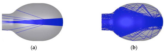
Figure 2.
Zemax modeling of 200 optical rays inside the stadium resonator (a) without, and (b) with a mirror coating.
3. Results
The spectrum of the resonator was measured in reflection before and after the gold deposition, using a broadband light centered at 1550 nm. An optical circulator was used to couple light into a single mode optical fiber with the microstadium in its tip, and the reflected signal was measured and displayed in a Yokogawa AQ6370D optical spectrum analyzer (OSA). The OSA was previously normalized to a flat cleaved SMF.
For comparison, the spectrum of the stadium resonator (Figure 3a—dark line) is depicted alongside the spectrum of a conventional microsphere (Figure 3a—light line). The plot for the conventional microsphere shows a low amplitude signal, slightly decreasing in intensity for higher wavelengths. For the stadium resonator, new optical paths are introduced, which leads to multiple light reflections inside the structure, producing an interferometric spectral modulation with increased amplitude, similar to a random signal. However, the intensity of the random component is not considerably large, which was improved by coating the microstadium with a reflecting gold layer (Figure 3b). In this case, light is trapped inside the microstadium, decreasing losses to the outside.
Figure 3.
Reflection spectra of the stadium resonator (a) before and (b) after depositing the gold coating. In (a), the signal of a conventional microsphere is depicted for comparison (light plot).
The setup chosen for random laser operation consisted of a ring cavity configuration with feedback (Figure 4). An IPG Photonics 1K-C3-W erbium-doped fiber amplifier (EDFA) was used as a power supply and signal amplifier. The signal from the EDFA was coupled into a single mode fiber with the microstadium in its tip, using a high power optical circulator. The signal resulting from the interference of the multiple reflections inside the structure is redirected by the optical circulator into a 90:10 optical coupler, in which the signal is divided. Ten percent of the signal is measured and depicted in an OSA, and the remaining 90% is reintroduced in the cavity ring, where it is amplified by the EDFA, and again coupled into the microstadium. The successive interference and amplification of the signal results in the random “selection” of a preferable wavelength, or wavelengths, by the microstadium, for which the power is higher. The experimental setup is depicted in the scheme below.
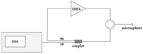
Figure 4.
Schematic of the optical setup for random fiber laser operation using the microstadium. OSA—optical spectrum analyzer; EDFA—erbium-doped fiber amplifier.
A critical pumping power of 110 mW was required for the appearance of lasing peaks in the spectrum. Increasing the pumping power above threshold, the OSA depicted spectral peaks with higher power above a quasi-stationary background around 0 mW (Figure 5). The multiple pulses are generated for random wavelengths selected by the microstadium, presenting the typical stochastic temporal and spectral behavior of a random laser. It is also possible to evince that lasing occurs around the highest gain region of the erbium spectrum, around 1531 nm. For each measurement, a power shift between pulses is observed, which translates into a random change in the peak’s amplitude and also in the lasing wavelength. The measurements were taken consecutively, within just a few seconds, likely not enough time to increase the microstadium’s temperature or to increase its volume due to thermal expansion. If the volume is kept unchanged, in principle there will not be any modifications to the optical paths inside the microstadium, and therefore the cavities will remain constant from one measurement to the next. Nonetheless, the shot-by-shot spectra in Figure 5 changes, which is due to variations in the random component of the signal even when external parameters or experimental conditions are kept constant. These shot-by-shot fluctuations, a term coined by Antenucci et al., are dictated by the modes and the overlap between them [32].
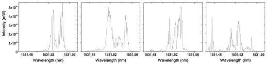
Figure 5.
Temporal and spectral random behavior in the region of highest erbium emission profile, for four consecutive measurements.
Lasing was demonstrated for the proposed microstadium geometry; however, the peak power is low due to the coupling to the microstadium. Despite the gold coating, the microstadium shows high losses in reflection which indicates that the back reflected light is not fully coupled and guided in the fiber core. While in conventional random lasers the numerical aperture has no impact on the output power, in the present 3D configuration this parameter can be a limiting factor on the amount of light being coupled from the microstadium into the core of the SMF. In the future, multimode fibers could be used to increase efficiency since their core diameter is substantially larger.
4. Discussion and Conclusions
A silica microstadium in an optical fiber tip was demonstrated for random laser generation. The microstadium geometry resembles a Bunimovich stadium, and its fabrication was obtained by creating and modifying a conventional microsphere using uniquely electric arc. The asymmetry of this geometry introduces new optical paths, and the interference of light reflections inside the microstadium were amplified by sputter-coating the structure with a uniform gold layer.
Lasing was achieved by introducing the microstadium in a ring cavity configuration alongside with an EDFA, and random lasing was identified as temporal and spectral random variations of the signal between consecutive measurements. The laser output power obtained was still low, for which silica microstadiums in multimode fiber tips could be considered in future studies. Possibilities to use microstadiums for wavelength-tunable laser configurations will also be endorsed.
Author Contributions
B.S. fabricated the device, conducted the characterization measurements of the device, analyzed the data, and wrote the manuscript; B.S. and O.F. designed the device; H.S. deposited the coating on the device; B.S. and A.G. conducted the random lasing measurements and discussed results alongside with M.B. and O.F.; M.B. and O.F. supervised the work. All authors read and commented on the manuscript.
Funding
Beatriz Silveira was funded by NanoSTIMA—North Portugal Regional Operational Programme (NORTE-01-0145-FEDER-000016), and COST Action MP1401 (39232)—European Cooperation in Science and Technology. André D. Gomes was funded by FCT—Fundação para a Ciência e Tecnologia (SFRH/BD/129428/2017).
Conflicts of Interest
The authors declare no conflict of interest. The funding sponsors had no role in the design of the study; in the collection, analyses, or interpretation of data; in the writing of the manuscript, and in the decision to publish the results.
References
- Letokhov, V.S. Generation of light by a scattering medium with negative resonance absorption. Zh. Eksp. Teor. Fiz. 1968, 53, 1442–1447. [Google Scholar]
- Andreasen, J.; Asatryan, A.A.; Botten, L.C.; Byrne, M.A.; Cao, H.; Ge, L.; Labonté, L.; Sebbah, P.; Stone, A.D.; Türeci, H.E.; et al. Modes of random lasers. Adv. Opt. Photonics 2011, 3, 88–127. [Google Scholar] [CrossRef]
- Wiersma, D.S. The physics and applications of random lasers. Nat. Phys. 2008, 4, 359–367. [Google Scholar] [CrossRef]
- Cao, H. Review on latest developments in random lasers with coherent feedback. J. Phys. A Math. Gen. 2005, 38, 10497. [Google Scholar] [CrossRef]
- Yang, L.; Yang, J.; Yang, Y.; Zhang, Z.; Wang, J.; Zhang, Z.; Xue, P.; Gong, Y.; Copner, N. Optical sensors using chaotic correlation fiber loop ring down. Opt. Express 2017, 25, 2031–2037. [Google Scholar] [CrossRef] [PubMed]
- Turitsyn, S.K.; Babin, S.A.; Churkin, D.V.; Vatnik, I.D.; Nikulin, M.; Podivilov, E.V. Random distributed feedback fibre lasers. Phys. Rep. 2014, 542, 133–193. [Google Scholar] [CrossRef]
- Churkin, D.V.; Sugavanam, S.; Vatnik, I.D.; Wang, Z.; Podivilov, E.V.; Babin, S.A.; Rao, Y.; Turitsyn, S.K. Recent advances in fundamentals and applications of random fiber lasers. Adv. Opt. Photonics 2015, 7, 516–569. [Google Scholar] [CrossRef]
- Argyris, A.; Syvridis, D.; Larger, L.; Annovazzi-Lodi, V.; Colet, P.; Fischer, I.; García-Ojalvo, J.; Mirasso, C.R.; Pesquera, L.; Shore, K.A. Chaos-based communications at high bit rates using commercial fibre-optic links. Nature 2005, 438, 343–346. [Google Scholar] [CrossRef] [PubMed]
- Uchida, A.; Amano, K.; Inoue, M.; Hirano, K.; Naito, S.; Someya, H.; Oowada, I.; Kurashige, T.; Shiki, M.; Yoshimori, S.; et al. Fast physical random bit generation with chaotic semiconductor lasers. Nat. Photonics 2008, 2, 728–732. [Google Scholar] [CrossRef]
- Redding, B.; Choma, M.A.; Cao, H. Spatial coherence of random laser emission. Opt. Lett. 2011, 36, 3404–3406. [Google Scholar] [CrossRef] [PubMed]
- Redding, B.; Choma, M.A.; Cao, H. Speckle-free laser imaging using random laser illumination. Nat. Photonics 2012, 6, 355–359. [Google Scholar] [CrossRef] [PubMed]
- Lahoz, F.; Martín, I.R.; Urgellés, M.; Marrero-Alonso, J.; Marín, R.; Saavedra, C.J.; Boto, A.; Díaz, M. Random laser in biological tissues impregnated with a fluorescent anticancer drug. Laser Phys. Lett. 2015, 12, 045805. [Google Scholar] [CrossRef]
- Markushev, V.M.; Zolin, V.F.; Briskina, C.M. Luminescence and stimulated emission of neodymium in sodium lanthanum molybdate powders. Quantum Electron. 1986, 16, 281–283. [Google Scholar] [CrossRef]
- Cao, H.; Zhao, Y.G.; Ho, S.T.; Seelig, E.W.; Wang, Q.H.; Chang, R.P.H. Random laser action in semiconductor powder. Phys. Rev. Lett. 1999, 82, 2278–2281. [Google Scholar] [CrossRef]
- Baudouin, Q.; Mercadier, N.; Guarrera, V.; Guerin, W.; Kaiser, R. A cold-atom random laser. Nat. Phys. 2013, 9, 357–360. [Google Scholar] [CrossRef]
- Doya, V.; Legrand, O.; Mortessagne, F.; Miniatura, C. Light scarring in an optical fiber. Phys. Rev. Lett. 2002, 88, 014102. [Google Scholar] [CrossRef] [PubMed]
- Lizárraga, N.; Puente, N.P.; Chaikina, E.I.; Leskova, T.A.; Méndez, E.R. Single-mode Er-doped fiber random laser with distributed Bragg grating feedback. Opt. Express 2009, 17, 395–404. [Google Scholar] [CrossRef] [PubMed]
- Quochi, F.; Cordella, F.; Mura, A.; Bongiovanni, G. Gain amplification and lasing properties of individual organic nanofibers. Appl. Phys. Lett. 2006, 88, 041106. [Google Scholar] [CrossRef]
- Bunimovich, L.A. On the ergodic properties of nowhere dispersing billiards. Commun. Math. Phys. 1979, 65, 295–312. [Google Scholar] [CrossRef]
- Shinohara, S.; Fukushima, T.; Harayama, T. Light emission patterns from stadium-shaped semiconductor microcavity lasers. Phys. Rev. A 2008, 77, 033807. [Google Scholar] [CrossRef]
- Lee, S.-B.; Lee, J.-H.; Chang, J.-S.; Moon, H.-J.; Kim, S.W.; An, K. Observation of Scarred Modes in Asymmetrically Deformed Microcylinder Lasers. Phys. Rev. Lett. 2002, 88, 033903. [Google Scholar] [CrossRef] [PubMed]
- Schwefel, H.G.L.; Rex, N.B.; Tureci, H.E.; Chang, R.K.; Stone, A.D.; Ben-Messaoud, T.; Zyss, J. Dramatic shape sensitivity of directional emission patterns from similarly deformed cylindrical polymer lasers. J. Opt. Soc. Am. B 2004, 21, 923–934. [Google Scholar] [CrossRef]
- Fukushima, T.; Harayama, T.; Davis, P.; Vaccaro, P.O.; Nishimura, T.; Aida, T. Quasi-stadium laser diodes with an unstable resonator condition. Opt. Lett. 2003, 28, 408–410. [Google Scholar] [CrossRef] [PubMed]
- Fukushima, T.; Harayama, T. Stadium and quasi-stadium laser diodes. IEEE Sel. Top. Quantum Electron. 2004, 10, 1039–1051. [Google Scholar]
- Chern, G.D.; Tureci, H.E.; Stone, A.D.; Chang, R.K.; Kneissl, M.; Johnson, N.M. Unidirectional lasing from InGaN multiple-quantum-well spiral-shaped micropillars. Appl. Phys. Lett. 2003, 83, 1710–1712. [Google Scholar] [CrossRef]
- Wiersig, J.; Hentschel, M. Unidirectional light emission from high-Q modes in optical microcavities. Phys. Rev. A 2006, 73, 031802. [Google Scholar] [CrossRef]
- Wiersig, J.; Hentschel, M. Combining directional light output and ultralow loss in deformed microdisks. Phys. Rev. Lett. 2008, 100, 033901. [Google Scholar] [CrossRef] [PubMed]
- Kurdoglyan, M.S.; Lee, S.Y.; Rim, S.; Kim, C.-M. Unidirectional lasing from a microcavity with a rounded isoceles triangle shape. Opt. Lett. 2004, 29, 2758–2760. [Google Scholar] [CrossRef] [PubMed]
- Kim, M.W.; Yi, C.H.; Rim, S.; Kim, C.M.; Kim, J.H.; Oh, K.R. Directional single mode emission in a microcavity laser. Opt. Express 2012, 20, 13651–13656. [Google Scholar] [CrossRef] [PubMed]
- Fang, W.; Cao, H.; Solomon, G.S. Control of lasing in fully chaotic open microcavities by tailoring the shape factor. Appl. Phys. Lett. 2007, 90, 081108. [Google Scholar] [CrossRef]
- Park, H.G.; Qian, F.; Barrelet, C.J.; Li, Y. Microstadium single-nanowire laser. Appl. Phys. Lett. 2007, 91, 251115. [Google Scholar]
- Antenucci, F.; Crisanti, A.; Leuzzi, L. The glassy random laser: Replica symmetry breaking in the intensity fluctuations of emission spectra. Sci. Rep. 2015, 5, 16792. [Google Scholar] [PubMed]
© 2018 by the authors. Licensee MDPI, Basel, Switzerland. This article is an open access article distributed under the terms and conditions of the Creative Commons Attribution (CC BY) license (http://creativecommons.org/licenses/by/4.0/).