Abstract
We experimentally investigate the transmission performance of 56 Gb/s four-level pulse amplitude modulation (PAM-4) over 30-km standard single mode fiber (SMF) using a C-band EML for low-cost metro and short-reach wavelength division multiplexing (WDM) applications. Bit error rate (BER) performance below the HD-FEC threshold is achieved for up to 30-km maximum reported distance without employing dispersion compensation fiber (DCF) in the link.
1. Introduction
Bit-rates up to 100 Gb/s and 400 Gb/s are currently investigated due to the ever-increasing capacity demands in metro and short-reach segments of the network [1]. Furthermore, the use of four-level pulse amplitude modulation (PAM-4) signals at 50 and 100 Gb/s has already been adopted as the baseline in the 400 GbE standardization (i.e., IEEE 802.3bs Task Force) for next generation 400 Gb/s or 1 Tb/s data transmission as a possible solution for client optics [2]. Wavelength division multiplexing (WDM)—i.e., 2 × 56 Gb/s or 8 × 56 Gb/s—could enable such transmission links. For example, 100 Gb/s on a single optical carrier and wavelength division multiplexing (WDM) is suggested by 400G-LR4 [2,3].
Low-cost deployment is essential in such cost-sensitive network segments, and cost-effective solutions that make use of C-band (i.e., 1550-nm wavelength) that do not imply the deployment of in-line dispersion compensating fiber (DCF) spans are desired. This approach would reduce the sensitivity requirements of such links and avoid the deployment of in-line amplifiers due to minimum fiber attenuation in that region. Much research effort has been put forth to investigate and develop intensity-modulated and direct-detection (IM/DD) 100-Gb/s optical links targeting a distance of up to 80 km over standard single mode fiber (SSMF) without the use of dispersion compensating fiber. The most recent transmission records in terms of data-rate and maximum transmission distance achieved involve the employment of high-performance Mach-Zenhder modulators (MZMs) and C-band wavelengths. In this context, 56 Gb/s four-level pulse amplitude modulated (PAM-4) signal transmission over 26 km of standard single mode fiber (SSMF) has been reported in [4]. Furthermore, 200 Gb/s PAM-4 and 168 Gb/s PAM-4 transmission has been reported in [5], enabled by a single integrated selector power digital-to-analog converter (SP-DAC), MZM, and feed-forward equalization (FFE) at the receiver to achieve transmission distance up to 500 m and 1 km, respectively. Longer transmission distance over 80-km SSMF of 112 Gb/s signaling at 1550 nm is reported in [6] using four-level pulse amplitude modulation and in [7] using 112 Gb/s vestigial side band (VSB) PAM-4. In [8], 248 Gb/s twin single-side band (SSB) discrete multi-tone (DMT) transmission is demonstrated using dual-drive (DD) MZM, while in [9], 100 Gb/s double side band (DSB) DMT enabled again by a DD-MZM is shown. In all aforementioned experiments, digital signal processing (DSP) at the receiver side is essential to recover the performance of the system and compensate for chromatic dispersion. However, in all aforementioned experiments [4,5,6,7,8,9], a relatively high-cost and performance transmitter (i.e., either a MZM or a DD-MZM) and external laser sources are used to enable the transmission over SSMF.
To reduce the cost and complexity of the system, low-cost, small footprint, and low-power dissipation lasers such as directly-modulated lasers (DMLs) together with PAM-4 format have been investigated to increase the data-rate in short reach links in the O-band due to the high chromatic dispersion tolerance provided by the SSMFs in that region [10]. In this context, 56 Gb/s PAM-4 has been demonstrated in [11] at 1310-nm wavelength using a non-linear compensation scheme for back-to-back transmission. Moreover, authors in [12] use the end-to-end frequency response to pre-compensate bandwidth limitations and a Volterra equalizer to post-compensate nonlinear signal distortion for a 1308.45-nm DMLs achieving 112 Gb/s PAM-4 transmission over 20-km SSMF.
However, the drawback of DMLs is that they allow for lower modulation bandwidths, and they can introduce nonlinear signal distortion due to modulation dynamics of the laser. Therefore, the use of electro-absorption modulated lasers (EMLs) is preferable, as the latter provides higher modulation bandwidths and can be used as low-cost and low form-factor transmitters. In this direction, 100-GHz bandwidth EMLs have been reported in [13] for 116 Gb/s signal generation at 1550 nm, and 96 Gb/s/λ PAM intensity modulation/direct detection (IM/DD) transmissions employing an EML and digital equalization is reported in [14] for maximum distances up to 4 km SSMF. In our previous work [15], we demonstrated a record transmission of 56 Gb/s PAM-4 over maximum 20-km of SSMF using a 1550-nm EML at the transmitter side and FFE in conjunction with maximum likelihood sequence equalization (MLSE) at the receiver to compensate for CD, which becomes a limiting factor in such systems [11,12,13,14,15,16].
In this work, we demonstrate a record transmission of 56 Gb/s PAM-4 over a transmission distance of 30 km. To achieve that, we optimize our transmitter and receiver implementations; i.e., we use a higher bandwidth digital-to-analogue converter at the transmitter and a higher sensitivity photo-diode with an integrated trans-impendence amplifier (TIA) at the receiver side. This enables the signal transmission over 20-km SSMF without the need for erbium-doped fiber amplifier (EDFA) employment, in contrast to [15], significantly improving the sensitivity requirements, and over 30-km by additionally pre-compensating for the end-to-end transfer function of the system. At the receiver side, we employ DSP consisting of a finite impulse response (FIR) filter that compensates partially for the accumulated CD, cascaded with an MLSE that is used to remove the residual inter-symbol-interference (ISI). Finally, we investigate the impact of the DSP complexity to the bit error rate (BER) performance for all transmission scenarios for both implementations.
2. Experimental Setup
The experimental implementations used to obtain the results of this paper are shown in Figure 1a,b. In Figure 1a, at the transmitter side, an arbitrary waveform generator (AWG) is used to provide a high integrity electrical signal. The AWG offers a bandwidth of 30 GHz and operates at 84 GS/s. Because of the AWG’s inherent hardware bandwidth limitations, signal pre-distortion is applied at the transmitter to compensate for it; i.e., the frequency response of the AWG is measured, and the inverse function is applied to the data to achieve a quasi-flat frequency response. The PAM-4 signal is generated in Matlab using a pseudo-random binary sequence (PRBS) of length 215 − 1 that is mapped to the corresponding PAM-4 symbols. The obtained symbol sequences are then downloaded to the AWG, and a 330 mV peak-to-peak 28 GBd PAM-4 signal is generated at its output, shown as inset (i) in Figure 1a. The electrical signal is adjusted in amplitude by an RF attenuator in line with a microwave amplifier. The electrical signal at the output of the RF amplifier (shown as inset (ii) in Figure 1a) is then used to drive the EML. Both the driving amplitude and the bias point of the EML are optimized to achieve the optimum performance under each transmission scenario. The output of the EML is approximately 0 dBm. A temperature controller is used to stabilize the operating point of the EML during the experiments. The 56 Gb/s PAM-4 optical signal at the output of the EML is then launched over standard single mode fiber spools of length 10-km, 15-km, 20-km, 25-km, and 30-km SSMF. The signal is detected on a 22-GHz p-i-n photodiode (PD) with integrated TIA. An EDFA is used in the link only to enable transmission higher that 25 km. The received optical power is varied before the receiver by a variable optical attenuator (VOA), and the optical power is monitored on a power-meter (PM) to test the BER transmission performance of the 56 Gb/s PAM-4 signal. Note that in order to evaluate the tolerance of our proposed scheme in the presence of CD, no dispersion compensation module is employed in the link. Next, the photocurrent is sampled on a real-time scope with channel bandwidth 33 GHz operating at 80 GS/s, and the data samples are stored and processed offline using the DSP blocks shown in Figure 1c. In the DSP part, first the signal is re-sampled to two samples per symbol and the amplitude is adjusted using an automatic gain control block (AGC) to enable appropriate convergence of the FIR equalizer. Then, timing recovery is performed [17] in order to compensate for timing drifts of the symbols, and next a hybrid implementation of an FIR equalizer followed by an MLSE block is employed to remove the inter-symbol interference induced by the chromatic dispersion in the link and decide on the transmitted symbol [18,19]. The BER is calculated at the output of both the FIR and the MLSE; BER is also calculated for the case when only an MLSE is employed to infer on its necessity at the input of the MLSE. We also investigate a second experimental configuration that employs a lower bandwidth transmitter (i.e., 15-GHz DAC), originally presented in [15], shown in Figure 1b. Results for back-to-back and after transmission over 10-km, 15-km, 20-km, 25-km, and 30-km are obtained in order to compare the performance of the two schemes shown in Figure 1a,b.
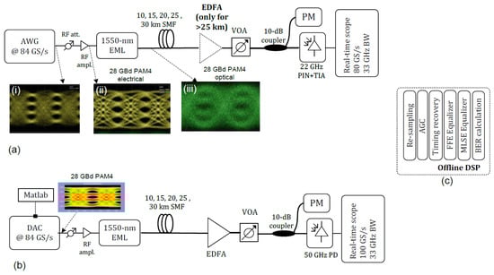
Figure 1.
(a): Experimental setup using a 30-GHz arbitrary waveform generator (AWG); (b) Experimental setup using a 15-GHz digital–analog converter (DAC) [15]; (c): Digital signal processing (DSP) algorithms used for offline processing for both implementations.
3. Results and Discussion
For both schemes, in the receiver DSP we investigated two cases: (i) when the multi-modulus algorithm (MMA) used for the FIR taps convergence is set to deliver a four level signal at its output; and (ii) when the MMA is modified so as its output corresponds to a seven-level poly-binary signal instead of a four-level one due to strong filtering imposed by the CD dominating the link.
For qualitative comparison, the 56 Gb/s received eye-diagrams for the implementation depicted in Figure 1b are shown in Figure 2 for the back-to-back case, and after 10-km, 15-km, and 20-km transmission. Here, we chose to illustrate the eye-diagrams for the scheme of Figure 1b, considering that it is a worst case scenario between the two implementations. As we can see in the first row, the received signal gets significantly degraded after all transmission scenarios compared to the back-to-back due to the chromatic dispersion that dominates in the link. For the back-to-back case when a four-level MMA is used, performance is superior compared to the case of a seven-level MMA employment, as indicated both by the eye-diagrams of the first column and the BER results shown in Figure 3; thus, it is used throughout this paper to obtain the BER performance for the back-to-back case for both schemes in Figure 1a,b. In particular, as we can see in Figure 3a, transmission is not feasible when no equalization is employed at the receiver. Making use of an FIR filter with 81 taps optimizes the BER by orders of magnitude, and brings the BER below the HD-FEC (hard decision forward error correction code) threshold; i.e., 4.5 × 10⁻³ [20], for −8 dBm. Employing an MLSE of either complexity (i.e., 16-, 64-, 256-, or 1024 state) at the output of the FIR filter does not further improve the performance. Results employing a seven-level MMA are shown in Figure 3b for comparison. As it is shown, this approach performs worse than a four-level MMA, since the bandwidth limitations are not so severe in the back-to-back case; however, they become critical for transmission over SSMF, making the seven-level MMA outperform the four-level one for links longer than 10-km for both schemes of Figure 1 (not shown here for the sake of brevity). So, to obtain all of the BER results presented in this paper for transmission over 10-km, 15-km, 20-km, 25-km, and 30-km, the MMA used for FIR taps convergence is modified so its output corresponds to a seven-level poly-binary signal instead of a four-level, due to strong filtering imposed by chromatic dispersion. This can be seen in Figure 2 in the second row, where we can observe that the eye-diagram becomes heavily distorted when the four-level MMA is employed for links longer than 10-km SMF, making the transmission unfeasible. The seven-level signal that is obtained at the output of the FIR will subsequently be fed to the input of the MLSE, operating in training mode. The latter is then able to decode the duo-binary signal and re-construct the original four-levels acting as a Viterbi decoder [21,22]. However, even if the employment of a seven-level MMA—depicted in the third row in Figure 2—improves the quality of the signal at the output of the FIR, the eye-opening becomes narrower for 15-km transmission, and finally the signal is severely degraded for 20-km such that the signal levels are no longer distinguishable.
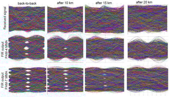
Figure 2.
Eye-diagrams before and after finite impulse response (FIR) for back-to-back, 10-km, 15-km, and 20-km for Figure 1b.
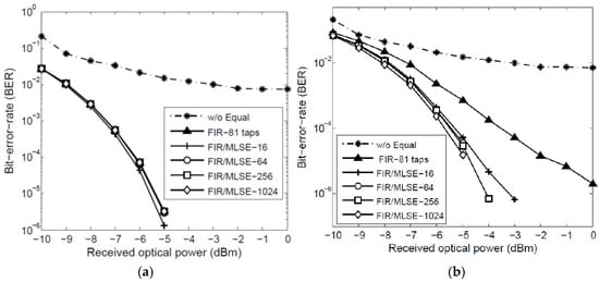
Figure 3.
56 Gb/s four-level pulse amplitude modulation (PAM-4) BER vs. received optical power for the back-to-back case when no equalization is employed (dashed line), when only an FIR filter is employed (triangles), and when an FIR followed by an 16-, 64-, 256-, and 1024 states MLSE equalizer is employed at the receiver (crosses, circles, squares, and diamonds, respectively). (a) When a four-level MMA and (b) when a seven-level MMA is used for FIR taps convergence (conditions: Experimental setup of Figure 1b).
Next, the results obtained using the experimental setup of Figure 1a are presented. The received eye-diagrams as well the eye-diagrams after the FIR are shown in Figure 4 for the back-to-back, and after transmission over 10-km, 15-km, 20-km, 25-km, and 30-km. For the back-to-back case, we observe that the four levels are already visible before any equalization, in contrast with the back-to-back case of Figure 2, indicating the impact of the improved signal generation in that scheme. For this scheme, distinguishable seven-level eye diagrams can be observed at the output of the FIR for links up to 20-km. However, the eye diagram gets degraded as the transmission distance increases due to the strong ISI imposed by CD as the reach is increased. This can be confirmed by observing the total system’s transfer function for all transmission scenarios, shown in Figure 5. Note here that the results of Figure 5 were obtained by sending a multi-tone signal from the AWG and measuring the frequency response using a real-time oscilloscope. The black line at Figure 5a represents the back-to-back case, and as we can see, the 3-dB bandwidth of the system is 28-GHz in that case. Comparing Figure 5a–e, we infer that the system’s transfer function (TF) entails a dip at 15-GHz, 13-GHz, 11-GHz, 10-GHz, and 9-GHz after transmission over 10-km, 15-km, 20-km, 25-km, and 30-km, respectively, as expected due to chromatic dispersion that dominates after transmission. In particular, Figure 5f shows in detail that the 3-dB bandwidth gets reduced down to 10-GHz, 8-GHz, 7-GHz, 6.5-GHz, and 6-GHz after transmission over 10-km, 15-km, 20-km, 25-km, and 30-km, respectively.
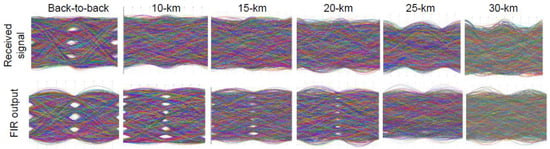
Figure 4.
Eye-diagrams before and after FIR for back-to-back, 10-km, 15-km, 20-km, 25-km, and 30-km for the experimental setup of Figure 1a.
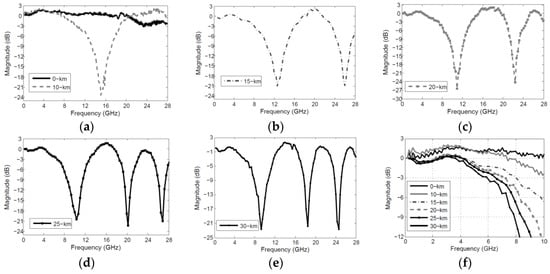
Figure 5.
The system’s transfer function measured for (a) the back-to-back case, and after transmission over (a) 10-km; (b) 15-km; (c) 20-km; (d) 25-km; and (e) 30-km; (f) 3-dB bandwidth of the transfer functions for all scenarios under investigation.
BER results for the back-to-back case for the scheme shown in Figure 1a are shown in Figure 6a, in black. For the discussion of the results, we will consider the 7% hard decision (HD) forward error correction code (FEC) threshold [20] (i.e., BER = 4.5 × 10⁻³), and the 20% soft decision FEC threshold [23] (i.e., BER = 2 × 10⁻²). As we can see, there is a 1 dB sensitivity improvement at the 7% HD-FEC BER threshold which approaches higher (i.e., ~2 dB) sensitivity improvement for lower BER values (BER in the order of 10−5) compared with the results of the second scheme (Figure 1b, in grey) [15]. The 7% HD-FEC BER threshold can be achieved at −9 dBm received optical power using only a FIR filter for equalization. MLSE employment after the FIR is also investigated, however there is no impact on the performance of the system when employing the latter, as the FIR alone can compensate for any signal distortion in that case.
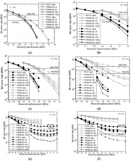
Figure 6.
BER vs. received optical power for (a) 10-km; (b) 15-km; (c) 20-km; (d) 20-km; (e) 25-km; and (f) 30-km for the scheme of Figure 1a,b in black and in grey, respectively.
The results for the 56 Gb/s PAM-4 transmission over 10 km for the scheme shown in Figure 1a are presented in Figure 6b, in black. The 7% HD-FEC threshold in that case can be achieved at −7.5 dBm received optical power only by employing an 81-taps FIR filter in the receiver’s DSP. Implementing the MLSE equalizer at the output of the FIR would result in further BER improvement by ~0.5 dB. Increasing the complexity of the MLSE up to 64, 256, or 1024 states does not bring further benefit to the overall BER performance. The BER results are improved by 1.5 dB compared to the results of the second scheme (Figure 1b, in grey) [15] when only an FIR is employed, and by 2 dB when an MLSE with 16 states (MLSE-16) is employed after the FIR. Higher complexity MLSE implementations are not justified, since the improvement in the performance is negligible, and it appears at lower BER values.
The results for 56 Gb/s PAM-4 transmission over 15 km for the scheme shown in Figure 1a are presented in Figure 6c, in black. The 7% HD-FEC threshold in that case can be achieved at −7 dBm received optical using an 81-taps FIR filter in the receiver’s DSP. The use of a cascaded MLSE scheme further improves the performance of the system by 1 dB for MLSE that entails 16, 64, 256, and 1024 states. As we can see, the BER performance is slightly improved by increasing the complexity up to 4096 states. Comparing these results to the results obtained for the second scheme (Figure 1b, in grey) [15], it is shown that BER performance at the 7% HD-FEC threshold can be optimized by 3.5 dB by using an FIR filter to compensate for the linear distortion of the channel, and by 4.5 dB when MLSE is used at the output of the FIR to compensate for the non-linear distortions of the system.
The results for the 56 Gb/s PAM-4 transmission over 20 km for the scheme shown in Figure 1a are presented in Figure 6d, in black. The 7% HD-FEC threshold in that case can be achieved at −5.5 dBm received optical using an 81-taps FIR filter. The hybrid implementation of FIR/MLSE scheme further improves the performance of the system by 1.5 dB at the 7% HD-FEC threshold. Note that in order to obtain these results, the TF of the system measured in Figure 5f is used to calculate the inverse TF and pre-distort the data at the transmitter side. This leads to a significant performance improvement compared to the results of the second scheme, shown in the same Figure 6d, in grey. Specifically, the sensitivity requirements are being relaxed, and at the same time, a suppression of the BER error floors is achieved. In particular, the transmission becomes feasible by only employing an FIR filter in contrast to the results obtained with the scheme of Figure 1b (in grey), while the use of the MLSE at the latter’s output leads to a 5.5, 3, 3.5, and 1.5 dB improvement if we compare the MLSE-16, -64, -256, and 1024 cases for both schemes, respectively.
The results for the 56 Gb/s PAM-4 transmission over 25 km for the scheme shown in Figure 1a are presented in Figure 6e in black. In contrast with the results based on the scheme of Figure 1b (in grey), transmission below the 7% HD-FEC threshold is now enabled by the implementation of an FIR followed by the MLSE at the receiver’s DSP. As we can see, in that case, the FIR filter alone cannot compensate for the ISI induced by the fiber link, and the employment of MLSE is essential to enable transmission below the HD-FEC threshold. MLSE with 16 states can achieve a BER = 4.5 × 10⁻³ at −3 dBm, while further increasing the memory of the MLSE so the latter consists of 64, 256, 1024 and 4096 states further improves the performance and brings the BER error floor down to BER ~ 10−4.
For the 30-km transmission case, the results based on the scheme of Figure 1a are presented in Figure 6f. In that case, transmission is not feasible below the 7% HD-FEC threshold if only an FIR filter or an FIR/MLSE scheme that incorporates 16, 64, or 256 states is employed. However, BER values below the 7% HD-FEC threshold are achieved by increasing the memory of the MLSE to 5 and 6 bits; i.e., to MLSE schemes that consist of 1024 and 4096 states. Lower complexity MLSE schemes could be used if a higher FEC overhead was to be employed to enable the transmission (i.e., 20% HD-FEC). For the 30-km transmission case, as was indicated by the eye-diagrams and by the narrow 6-GHz bandwidth system’s TF before, the performance gets significantly degraded by the chromatic dispersion in the link, such that the equalization schemes at the receiver cannot compensate for the signal distortion. Note that pre-compensation of the total system’s TF (Figure 5f) was implemented for the 25-km and 30-km cases, as was previously described in the 20-km transmission case. The sensitivity requirements of the scheme of Figure 1a at 7% HD-FEC threshold are summarized in Table 1. The 20% HD-FEC threshold is also drawn in Figure 6 so as to illustrate the sensitivity requirements for the corresponding reduced raw data rate.

Table 1.
Sensitivity requirements of the scheme of Figure 1a at 7% hard decision forward error correction code (HD-FEC) threshold.
Taking the MLSE-1024 case as reference, the power budget of the different transmission scenarios can be estimated as 8.8, 8, 8, 7.2 dBm, for back-to-back, 10-km, 15-km, and 20-km, and 5 and 4.2 dBm for MLSE-4096 for 25-km and 30-km. Power budget improvements could be achieved with advances in transmitter optical sub-assembly (TOSA) output powers in such systems.
Finally, in order to infer whether the use of the FIR filter at the input of the MLSE is essential, we take the scheme of Figure 1b as a worst case scenario, and we analyze the results omitting the FIR filter at the receiver’s DSP. We use only the MLSE with different degrees of complexity, and we calculate the BER for back-to-back, 10-km, 15-km, and 20-km. The results are shown in Figure 7. As it is shown, employing only an MLSE at the DSP results in a performance similar to employing the hybrid implementation of FIR/MLSE for the back-to-back-case (Figure 6a). For 10-km, MLSE alone performs worse than the FIR/MLSE scheme (Figure 6b) by ~1.5 dB at 7% HD-FEC threshold. For 15-km and 20-km transmission, the MLSE scheme alone cannot make the transmission feasible, regardless of the increase of the MLSE states; so, the FIR/MLSE implementation proves essential in that case to enable the 56 Gb/s PAM-4 transmission. So, the FIR filter proves essential to improve the performance if implemented before the MLSE, because it partially equalizes the signal and compensates for linear and quasi-linear distortions, so the MLSE can cope with the residual ISI and distortions of the signal, making the transmission feasible over 30-km.
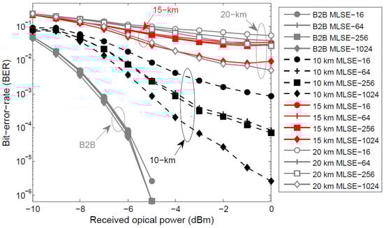
Figure 7.
BER vs. received optical power when a 16-, 64-, 256-, and 1024-level MLSE.
4. Conclusions
We have demonstrated a record transmission distance of 30-km for 56 Gb/s PAM-4 signaling, with direct detection, employing a C-band EML without using any in-line dispersion compensation in the link. CD compensation is done at the receiver side by digital signal processing algorithms using a hybrid implementation of an FIR followed by an MLSE for signal equalization, making use of the benefits of both equalization schemes. First, the FIR filter acquires the channel response and partially equalizes the signal, performs linear feed forward signal equalization, and is used to increase the eye-opening of the received signal. However, only the FIR is not sufficient to completely remove the accumulated ISI after transmission; thus, the implementation of the MLSE at its output significantly enhances the performance, as it compensates for the bandwidth limitations and residual ISI and decodes the signal. Results showed that the hybrid FIR/MLSE scheme can enable transmission below the 7% HD-FEC threshold up to 20-km without the need for optical amplification in the link, and up to 30-km when an EDFA is employed. If a 20% overhead HD-FEC is used, error-free operation can be achieved with relaxed sensitivity requirements, as indicated by the results. In that case, lower complexity (i.e., a MLSE-16 states scheme) can also enable transmission up to 30-km. The proposed scheme would reduce the sensitivity requirements of short-reach links making use of the 1550-nm wavelength and avoid the deployment of in-line amplifiers due to minimum fiber attenuation in that region. At the same time, it minimizes the cost of the network, utilizing inexpensive small form-factor EMLs at the transmitter, and avoids making use of expensive components such as MZMs or DD-MZMs to enable the transmission. For an actual implementation, the DAC can be integrated together with transmitter and the receiver’s DSP in a single chip, thus reducing the cost of a real implementation. Simplifications in the DSP implementations using MLSE variants that use less states to achieve the same performance would reduce the power consumption of the scheme [24]. As far as latency is concerned, all MLSE schemes experience similar value, as the data are processed symbol by symbol in the trellis; i.e., in one CMOS clock cycle, we process all branches together.
Author Contributions
F.K. conceived, designed, and performed the experiments, analyzed the data and wrote the paper; N.S. designed the digital signal processing algorithms. C.P. and Q.Z. revised the manuscript.
Conflicts of Interest
The authors declare no conflict of interest.
References
- The 2016 Ethernet Roadmap. Available online: http://www.ethernetalliance.org/roadmap/ (accessed on 28 March 2016).
- IEEE P802.3bs 200 Gb/s and 400 Gb/s Ethernet Task Force. Available online: http://www.ieee802.org/3/bs/ (accessed on 16 November 2016).
- Welch, B. IEEE P802.3bs 2014. Available online: http://www.ieee802.org/3/bs/public/14_05/welch_3bs_01_0514.pdf (accessed on 1 May 2014).
- Chen, C.; Tang, X.; Zhang, Z. Transmission of 56-Gb/s PAM-4 over 26-km single mode fiber using maximum likelihood sequence estimation. In Proceedings of the Optical Fiber Communications Conference, Los Angeles, CA, USA, 22–26 March 2015.
- Mestre, M.A.; Jorge, F.; Mardoyan, H.; Estarán, J.; Blache, F.; Angelini, P.; Konczykowska, A.; Riet, M.; Nodjiadjim, V.; Dupuy, J.-Y.; et al. 100-Gbaud PAM-4 intensity-modulation direct-detection transceiver for datacenter interconnect. In Proceedings of the IEEE European Conference on Optical Communications, Duesseldorf, Germany, 18–22 September 2016.
- Eiselt, N.; Heide, S.; Griesser, H.; Eiselt, M.; Okonkwo, C.; Vegas Olmos, J.J.; Tafur Monroy, I. Experimental demonstration of 112-Gbit/s PAM-4 over up to 80 km SSMF at 1550 nm for inter-DCI applications. In Proceedings of the IEEE European Conference on Optical Communications, Duesseldorf, Germany, 18–22 September 2016.
- Lee, J.; Kaneda, N.; Chen, Y.K. 112-Gbit/s intensity-modulated direct-detect vestigial-sideband PAM4 transmission over an 80-km SSMF link. In Proceedings of the IEEE European Conference on Optical Communications, Duesseldorf, Germany, 18–22 September 2016.
- Zhang, L.; Zuo, T.; Zhang, Q.; Zhou, E.; Liu, G.N. Single wavelength 248-Gb/s transmission over 80-km SMF based on twin-SSB-DMT and direct detection. In Proceedings of the IEEE European Conference on Optical Communications, Duesseldorf, Germany, 18–22 September 2016.
- Zhou, J.; Zhang, L.; Zuo, T.; Zhang, Q.; Zhang, S.; Zhou, E.; Liu, G.N. Transmission of 100-Gb/s DSB-DMT over 80-km SMF using 10-G class TTA and direct-detection. In Proceedings of the IEEE European Conference on Optical Communications, Duesseldorf, Germany, 18–22 September 2016.
- Zhong, K.; Zhou, X.; Gao, Y.; Chen, W.; Man, J.; Zeng, L.; Tao Lau, A.P.; Lu, C. 140-Gb/s 20-km transmission of PAM-4 signal at 1.3 μm for short reach communications. IEEE Photonics Technol. Lett. 2015, 27, 1757–1760. [Google Scholar] [CrossRef]
- Kikuchi, N.; Hirai, R.; Fukui, T. Non-linearity compensation of high-speed PAM4 signals from directly-modulated laser at high extinction ratio. In Proceedings of the IEEE European Conference on Optical Communications, Duesseldorf, Germany, 18–22 September 2016.
- Gao, Y.; Cartledge, J.C.; Yam, S.S.-H.; Rezania, A.; Matsui, Y. 112 Gb/s PAM-4 using a directly modulated laser with linear pre-compensation and nonlinear post-compensation. In Proceedings of the IEEE European Conference on Optical Communications, Duesseldorf, Germany, 18–22 September 2016.
- Ozolins, O.; Olmedo, M.I.; Pang, X.; Gaiarin, S.; Kakkar, A.; Udalcovs, A.; Engenhardt, K.M.; Asyngier, T.; Schatz, R.; Li, J.; et al. 100 GHz EML for high speed optical interconnect applications. In Proceedings of the European Conference on Optical Communications, Duesseldorf, Germany, 18–22 September 2016.
- Pang, X.; Ozolins, O.; Gaiarin, S.; Olmedo, M.I.; Schatz, R.; Westergren, U.; Zibar, D.; Popov, S.; Jacobsen, G. Evaluation of high-speed EML-based IM/DD links with PAM modulations and low-complexity equalization. In Proceedings of the European Conference on Optical Communications, Duesseldorf, Germany, 18–22 September 2016.
- Karinou, F.; Stojanovic, N.; Prodaniuc, C. 56 Gb/s 20-km Transmission of PAM-4 Signal Employing an EML in C-band without in-line Chromatic Dispersion Compensation. In Proceedings of the IEEE European Conference on Optical Communications, Duesseldorf, Germany, 18–22 September 2016.
- Erasme, D.; Anfray, T.; Chaibi, M.E.; Kechaou, K.; Petit, J.; Aubin, G.; Merghem, K.; Kazmierski, C.; Provost, J.K.; Chanclou, P.; et al. The dual-electroabsorption modulated laser, a flexible solution for amplified and dispersion uncompensated networks over standard fiber. IEEE J. Lightw. Technol. 2014, 32, 4068–4078. [Google Scholar]
- Gardner, F.M. A BPSK/QPSK timing-error detector for sampled receivers. Trans. Commun. 1986, 34, 423–429. [Google Scholar] [CrossRef]
- Forney, G. Maximum-likelihood sequence estimation of digital sequences in the presence of intersymbol interference. Trans. Inf. Theory 1972, 18, 363–378. [Google Scholar] [CrossRef]
- Karinou, F.; Prodaniuc, C.; Stojanovic, N.; Ortsiefer, M.; Daly, A.; Hohenleitner, R.; Kögel, B.; Neumeyr, C. Directly PAM-4 modulated 1530-nm VCSEL enabling 56 Gb/s/λ data-center interconnects. IEEE Photonics Technol. Lett. 2015, 27, 1872–1875. [Google Scholar] [CrossRef]
- Scholten, M.; Coe, T.; Dillard, J. Continuously-interleaved BCH (CI-BCH) FEC delivers best in class NECG for 40G and 100G metro applications. In Proceedings of the Optical Fiber Communications Conference, Camarillo, CA, USA, 21–25 March 2010.
- Kupfer, T.; Fludger, C.; Langenbach, S.; Stojanovic, N.; Dorschky, C.; Schulien, C. Digital equalization at 10.7 Gb/s using maximum likelihood sequence estimation—A present and future technology. In Proceedings of the IEE Seminar on Optical Fiber Communications and Electronic Signal Processing, London, UK, 15 December 2005.
- Proakis, J.G. Digital Communications, 4th ed.; McGraw-Hill: New York, NY, USA, 2001. [Google Scholar]
- Chang, D.; Chang, D; Yu, F.; Xiao, Z.; Li, Y.; Stojanovic, N.; Xie, C.; Shi, X.; Xu, X.; Xiong, Q. FPGA verification of a single QC-LDPC code for 100Gb/s optical systems without error floor down to BER of 10−15. In Proceedings of the Optical Fiber Communications Conference, Los Angeles, CA, USA, 6–10 March 2011.
- Finamore, W.A.; Pimentel, C.J.; Anderson, J.B. M-algorithm decoding of convolutional code combined with CPM. In Proceedings of the SBT/IEEE International Telecommunications Symposium (SBT/IEEE ITS), Rio de Janerio, Brazil, 3–6 September 1990; pp. 514–518.
© 2017 by the authors. Licensee MDPI, Basel, Switzerland. This article is an open access article distributed under the terms and conditions of the Creative Commons Attribution (CC BY) license ( http://creativecommons.org/licenses/by/4.0/).