Design Study of Time-Preserving Grating Monochromators for Ultrashort Pulses in the Extreme-Ultraviolet and Soft X-Rays


Abstract
:1. Introduction
2. Single-Grating Monochromators for Ultrashort Pulses
3. Pulse-Preserving Monochromators
4. Single-Grating Monochromators for HHs
5. Single-Grating Monochromators for FELs
6. Conclusions
Author Contributions
Conflicts of Interest
References
- Marciak-Kozlowska, J.; Kozlowski, M. From Femto-To Attoscience and Beyond; Nova Science Publisher: Hauppauge, NY, USA, 2009. [Google Scholar]
- Diels, J.C.; Rudolph, W. Ultrashort Laser Pulse Phenomena, 2nd ed.; Elsevier: London, UK, 2006; pp. 277–394. [Google Scholar]
- Jaeglè, P. Coherent Sources of XUV Radiation; Springer: New York, NY, USA, 2006; pp. 277–344. [Google Scholar]
- Krausz, F.; Ivanov, M. Attosecond physics. Rev. Mod. Phys. 2009, 81, 163–234. [Google Scholar] [CrossRef]
- Sansone, G.; Poletto, L.; Nisoli, M. High-energy attosecond light sources. Nat. Photonics 2011, 5, 655–663. [Google Scholar] [CrossRef]
- Gallmann, L.; Cirelli, C.; Keller, U. Attosecond Science: Recent Highlights and Future Trends. Ann. Rev. Phys. Chem. 2012, 63, 447–469. [Google Scholar] [CrossRef] [PubMed]
- Krausz, F.; Stockman, M.I. Attosecond metrology: From electron capture to future signal processing. Nat. Photonics 2014, 8, 205–213. [Google Scholar] [CrossRef]
- Free-Electron Laser FLASH. Available online: http://flash.desy.de/ (accessed on 30 January 2017).
- SACLA (XFEL). Available online: http://xfel.riken.jp/eng/ (accessed on 30 January 2017).
- LCLS—Linac Coherent Light Source. Available online: http://lcls.slac.stanford.edu/ (accessed on 30 January 2017).
- FERMI. Available online: https://www.elettra.trieste.it/lightsources/fermi.html (accessed on 30 January 2017).
- Sekikawa, T.; Okamoto, T.; Haraguchi, E.; Yamashita, M.; Nakajima, T. Two-photon resonant excitation of a doubly excited state in He atoms by high-harmonic pulses. Opt. Express 2008, 16, 21922–21929. [Google Scholar] [CrossRef] [PubMed]
- Zurch, M.; Kern, C.; Spielmann, C. XUV coherent diffraction imaging in reflection geometry with low numerical aperture. Opt. Express 2013, 21, 21131–21147. [Google Scholar] [CrossRef] [PubMed]
- Martins, M.; Wellhöfer, M.; Hoeft, J.T.; Wurth, W.; Feldhaus, J.; Follath, R. Monochromator beamline for FLASH. Rev. Sci. Instrum. 2006, 77, 115108. [Google Scholar] [CrossRef]
- Guerassimova, N.; Dziarzhytski, S.; Feldhaus, J. The monochromator beamline at FLASH: Performance, capabilities and upgrade plans. J. Mod. Opt. 2011, 58, 1480–1485. [Google Scholar] [CrossRef]
- Schlotter, W.F.; Turner, J.J.; Rowen, M.; Heimann, P.; Holmes, M.; Krupin, O.; Messerschmidt, M.; Moeller, S.; Krzywinski, J.; Soufli, R.; et al. The soft X-ray instrument for materials studies at the linac coherent light source X-ray free-electron laser. Rev. Sci. Instrum. 2012, 88, 043107. [Google Scholar] [CrossRef] [PubMed]
- Heimann, P.A.; Glover, T.E.; Plate, D.; Lee, H.J.; Brown, V.C.; Padmore, H.A.; Schoenlein, R.W. The Advanced Light Source (ALS) Slicing Undulator Beamline. AIP Conf. Proc. 2007, 879, 1195–1197. [Google Scholar]
- Brzhezinskaya, M.; Firsov, A.; Holldack, K.; Kachel, T.; Mitzner, R.; Pontius, N.; Schmidt, J.-S.; Sperling, M.; Stamm, C.; Fohlisch, A.; et al. A novel monochromator for experiments with ultrashort X-ray pulses. J. Synchr. Radiat. 2013, 20, 1–9. [Google Scholar] [CrossRef] [PubMed]
- Holldack, K.; Bahrdt, J.; Balzer, A.; Bovensiepen, U.; Brzhezinskaya, M.; Erko, A.; Eschenlohr, A.; Follath, R.; Firsov, A.; Frentrup, W.; et al. FemtoSpeX: A versatile optical pump-soft X-ray probe facility with 100 fs X-ray pulses of variable polarization. J. Synchr. Radiat. 2013, 21, 1090–1104. [Google Scholar] [CrossRef] [PubMed]
- Wieland, M.; Frueke, R.; Wilhein, T.; Spielmann, C.; Pohl, M.; Kleineberg, U. Submicron extreme ultraviolet imaging using high-harmonic radiation. Appl. Phys. Lett. 2002, 81, 2520–2522. [Google Scholar] [CrossRef]
- Mashiko, H.; Suda, A.; Midorikawa, K. Focusing coherent soft-X-ray radiation to a micrometer spot size with an intensity of 1014 W/cm2. Opt. Lett. 2004, 29, 1927–1929. [Google Scholar] [CrossRef] [PubMed]
- Poletto, L.; Tondello, G. Time-compensated EUV and soft X-ray monochromator for ultrashort high-order harmonic pulses. Pure Appl. Opt. 2001, 3, 374–379. [Google Scholar] [CrossRef]
- Poletto, L.; Frassetto, F. Time-preserving monochromators for ultrafast extreme-ultraviolet pulses. Appl. Opt. 2010, 49, 5465–5473. [Google Scholar] [CrossRef] [PubMed]
- Poletto, L. Time-compensated grazing-incidence monochromator for extreme-ultraviolet and soft X-ray high-order harmonics. Appl. Phys. B 2004, 78, 1013–1016. [Google Scholar] [CrossRef]
- Poletto, L.; Villoresi, P.; Benedetti, E.; Ferrari, F.; Sansone, G.; Stagira, S.; Nisoli, M. Intense femtosecond extreme ultraviolet pulses by using a time-delay compensated monochromator. Opt. Lett. 2007, 32, 2897–2899. [Google Scholar] [CrossRef] [PubMed]
- Poletto, L.; Villoresi, P.; Frassetto, F.; Calegari, F.; Ferrari, F.; Lucchini, M.; Sansone, G.; Nisoli, M. Time-delay compensated monochromator for the spectral selection of extreme-ultraviolet high-order laser harmonics. Rev. Sci. Instrum. 2009, 80, 123109. [Google Scholar] [CrossRef]
- Ito, M.; Kataoka, Y.; Okamoto, T.; Yamashita, M.; Sekikawa, T. Spatiotemporal characterization of single-order high harmonic pulses from time-compensated toroidal-grating monochromator. Opt. Express 2010, 18, 6071–6078. [Google Scholar] [CrossRef] [PubMed]
- Igarashi, H.; Makida, A.; Ito, M.; Sekikawa, T. Pulse compression of phase-matched high harmonic pulses from a time-delay compensated monochromator. Opt. Express 2012, 20, 3725–3732. [Google Scholar] [CrossRef] [PubMed]
- Poletto, L.; Villoresi, P. Time-compensated monochromator in the off-plane mount for extreme-ultraviolet ultrashort pulses. Appl. Opt. 2006, 45, 8577–8585. [Google Scholar] [CrossRef] [PubMed]
- Pascolini, M.; Bonora, S.; Giglia, A.; Mahne, N.; Nannarone, S.; Poletto, L. Gratings in a conical diffraction mounting for an extreme-ultraviolet time-delay-compensated monochromator. Appl. Opt. 2006, 45, 3253–3262. [Google Scholar] [CrossRef] [PubMed]
- Frassetto, F.; Cacho, C.; Froud, C.A.; Turcu, I.C.; Villoresi, P.; Bryan, W.A.; Springate, E.; Poletto, L. Single-grating monochromator for extreme-ultraviolet ultrashort pulses. Opt. Express 2011, 19, 19169–19181. [Google Scholar] [CrossRef]
- Grazioli, C.; Callegari, C.; Ciavardini, A.; Coreno, M.; Frassetto, F.; Gauthier, D.; Golob, D.; Ivanov, R.; Kivimäki, A.; Mahieu, B.; et al. CITIUS: An infrared-extreme ultraviolet light source for fundamental and applied ultrafast science. Rev. Sci. Instrum. 2014, 85, 023104. [Google Scholar] [CrossRef] [PubMed]
- Poletto, L.; Miotti, P.; Frassetto, F.; Spezzani, C.; Grazioli, C.; Coreno, M.; Ressel, B.; Gauthier, D.; Ivanov, R.; Ciavardini, A.; et al. Double-configuration grating monochromator for extreme-ultraviolet ultrafast pulses. Appl. Opt. 2014, 53, 5879–5888. [Google Scholar]
- Ojeda, J.; Arrell, C.A.; Grilj, J.; Frassetto, F.; Mewes, L.; Zhang, H.; Mourik, F.; Poletto, L.; Chergui, M. Harmonium: A pulse preserving source of monochromatic EUV (30–110 eV) radiation for ultrafast photoelectron spectroscopy of liquids. Struct. Dyn. 2016, 3, 023602. [Google Scholar] [CrossRef] [PubMed]
- Poletto, L.; Frassetto, F. Single-grating monochromators for extreme-ultraviolet ultrashort pulses. Appl. Sci. 2013, 3, 1–13. [Google Scholar] [CrossRef]
- Poletto, L.; Bonora, S.; Pascolini, M.; Villoresi, P. Instrumentation for analysis and utilization of extreme-ultraviolet and soft X-ray high-order harmonics. Rev. Sci. Instrum. 2004, 75, 4413–4418. [Google Scholar] [CrossRef]
- Salières, P.; Ditmire, T.; Perry, M.D.; L’Huillier, A.; Lewenstein, M. Angular distributions of high-order harmonics generated by a femtosecond laser. J. Phys. B. At. Mol. Opt. Phys. 1996, 29, 4771–4786. [Google Scholar] [CrossRef] [Green Version]
- Nisoli, M.; Priori, E.; Sansone, G.; Stagira, S.; Cerullo, G.; De Silvestri, S.; Altucci, C.; Bruzzese, R.; de Lisio, C.; Villoresi, P.; et al. High-Brightness High-Order Harmonic Generation by Truncated Bessel Beams in the Sub-10-fs Regime. Phys. Rev. Lett. 2002, 88, 33902. [Google Scholar] [CrossRef] [PubMed]
- Takahashi, E.J.; Nabekawa, Y.; Midorikawa, K. Low-divergence coherent soft X-ray source at 13 nm by high-order harmonics. Appl. Phys. Lett. 2004, 84, 4. [Google Scholar] [CrossRef]
- Jin, C.; Lin, C.D. Comparison of high-order harmonic generation of Ar using truncated Bessel and Gaussian beams. Phys. Rev. A 2012, 85, 033423. [Google Scholar] [CrossRef]
- Ye, P.; Teng, H.; He, X.-K.; Zhong, S.-Y.; Wang, L.-F.; Zhan, M.-J.; Zhang, W.; Yun, C.-X.; Wei, Z.-Y. Minimizing the angular divergence of high-order harmonics by truncating the truncated Bessel beam. Phys. Rev. A 2014, 90, 063808. [Google Scholar] [CrossRef]
- Heimann, P.; Krupin, O.; Schlotter, W.F.; Turner, J.; Krzywinski, J.; Sorgenfrei, F.; Messerschmidt, M.; Bernstein, D.; Chalupský, J.; Hájková, V.; et al. Linac Coherent Light Source soft X-ray materials science instrument optical design and monochromator commissioning. Rev. Sci. Instrum. 2011, 82, 093104. [Google Scholar] [CrossRef] [PubMed]
- Frassetto, F.; Ploenjes, E.; Kuhlmann, M.; Poletto, L. Time-delay-compensated grating monochromator for FEL beamlines. In SPIE Proceedings 9210, X-ray Free-Electron Lasers: Beam Diagnostics, Beamline Instrumentation, and Applications II; SPIE: San Diego, CA, USA, 2014; Volume 9210. [Google Scholar]


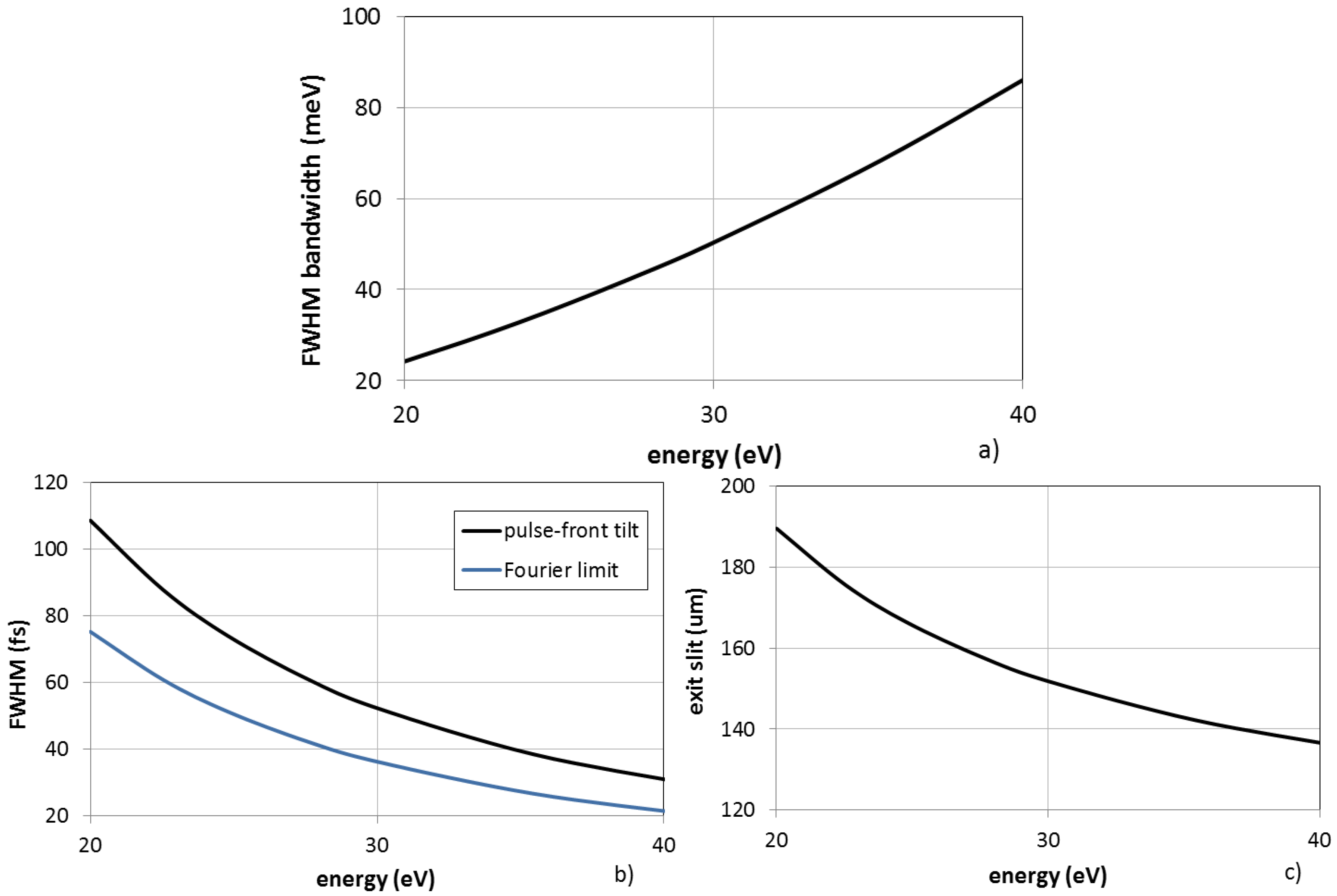
| Spectral Region | 20–40 eV | |
| CDM Grating | Subtended angle | 152°, external order |
| Groove density | 600 gr/mm | |
| Entrance/output arm | 700 mm | |
| OPM Grating | Altitude angle | 6° |
| Groove density | 1200 gr/mm | |
| Entrance/output arm | 1200 mm |
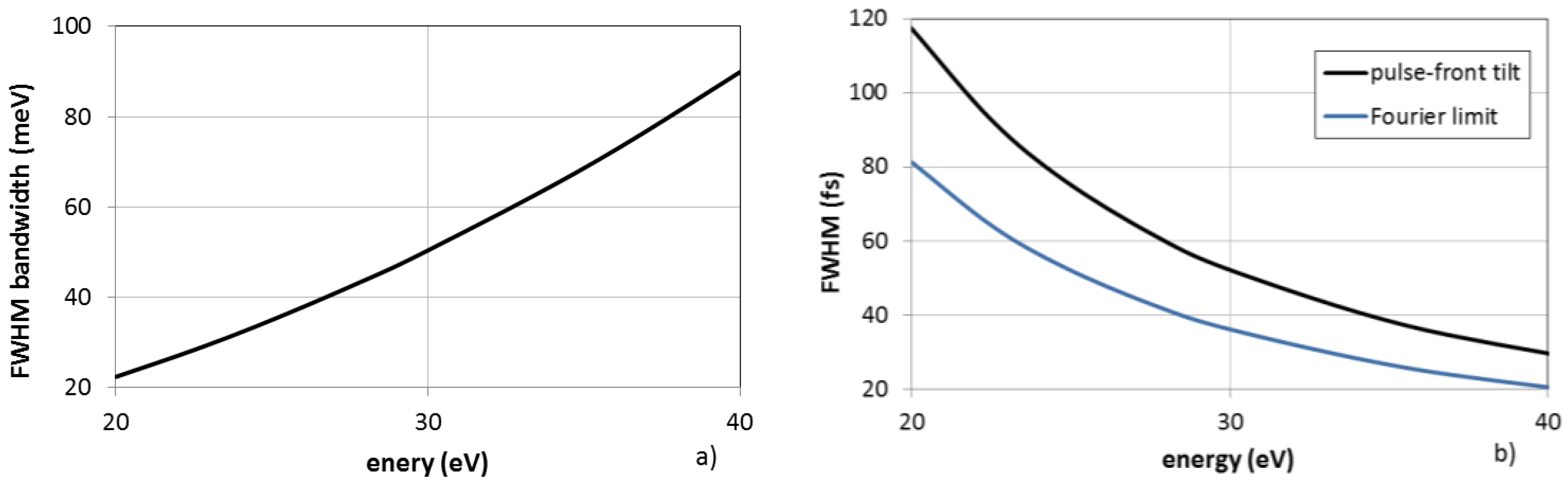
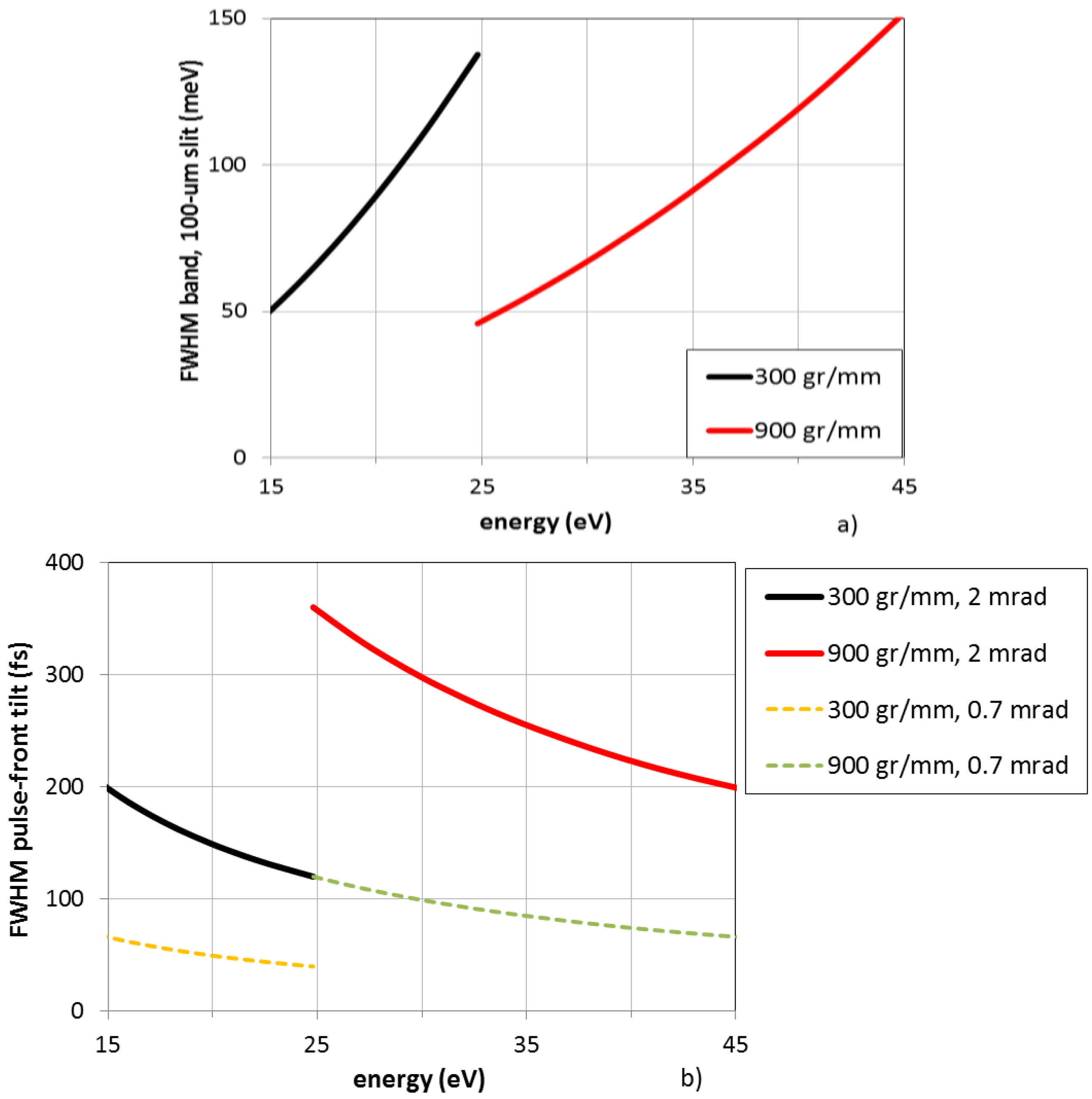
| Spectral Region | 15–45 eV | |
| Energy Bandwidth | 100 meV | |
| Source Divergence | 2 mrad FWHM | |
| OPM Gratings | 2 gratings | |
| Entrance arm | 1200 mm | |
| Output arm | 1200 mm | |
| Grating 1 | Energy region | 15–25 eV |
| Groove density | 300 gr/mm | |
| Grating 2 | Energy region | 25–45 eV |
| Groove density | 900 gr/mm |
© 2017 by the authors. Licensee MDPI, Basel, Switzerland. This article is an open access article distributed under the terms and conditions of the Creative Commons Attribution (CC BY) license ( http://creativecommons.org/licenses/by/4.0/).
Share and Cite
Frassetto, F.; Fabris, N.; Miotti, P.; Poletto, L. Design Study of Time-Preserving Grating Monochromators for Ultrashort Pulses in the Extreme-Ultraviolet and Soft X-Rays. Photonics 2017, 4, 14. https://doi.org/10.3390/photonics4010014
Frassetto F, Fabris N, Miotti P, Poletto L. Design Study of Time-Preserving Grating Monochromators for Ultrashort Pulses in the Extreme-Ultraviolet and Soft X-Rays. Photonics. 2017; 4(1):14. https://doi.org/10.3390/photonics4010014
Chicago/Turabian StyleFrassetto, Fabio, Nicola Fabris, Paolo Miotti, and Luca Poletto. 2017. "Design Study of Time-Preserving Grating Monochromators for Ultrashort Pulses in the Extreme-Ultraviolet and Soft X-Rays" Photonics 4, no. 1: 14. https://doi.org/10.3390/photonics4010014
APA StyleFrassetto, F., Fabris, N., Miotti, P., & Poletto, L. (2017). Design Study of Time-Preserving Grating Monochromators for Ultrashort Pulses in the Extreme-Ultraviolet and Soft X-Rays. Photonics, 4(1), 14. https://doi.org/10.3390/photonics4010014