Mid-Infrared Quantum-Dot Quantum Cascade Laser: A Theoretical Feasibility Study


Abstract
:
1. Introduction
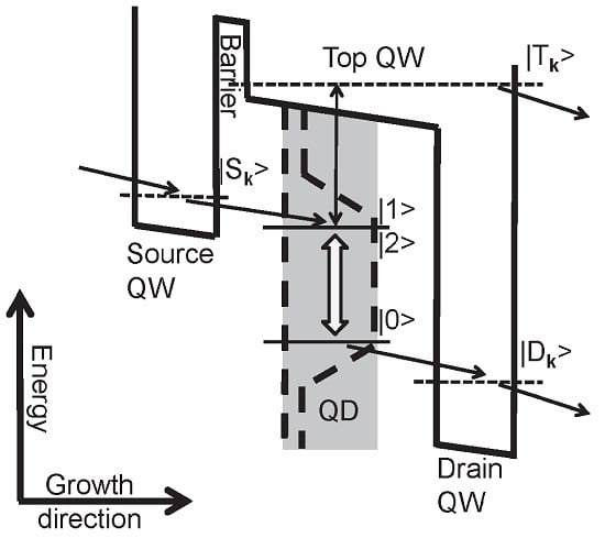
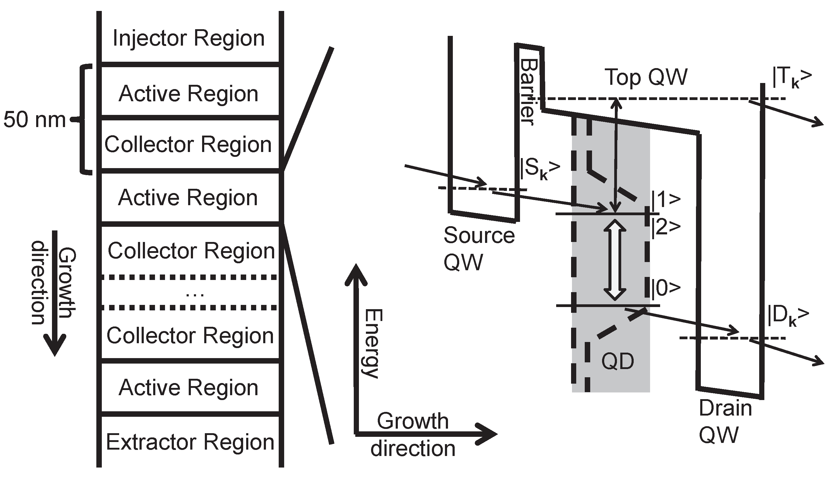
2. Setup
3. Results
3.1. QD Material Parameters
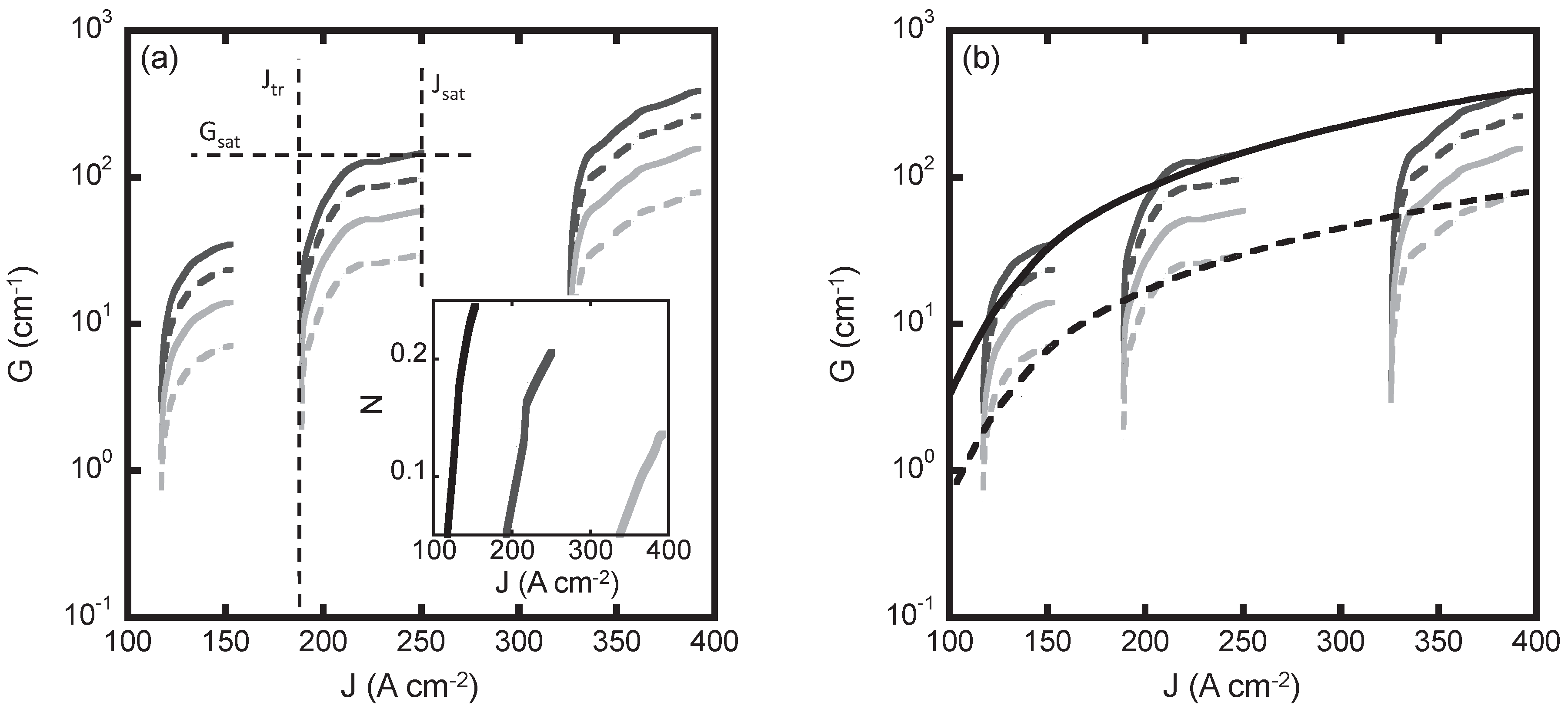
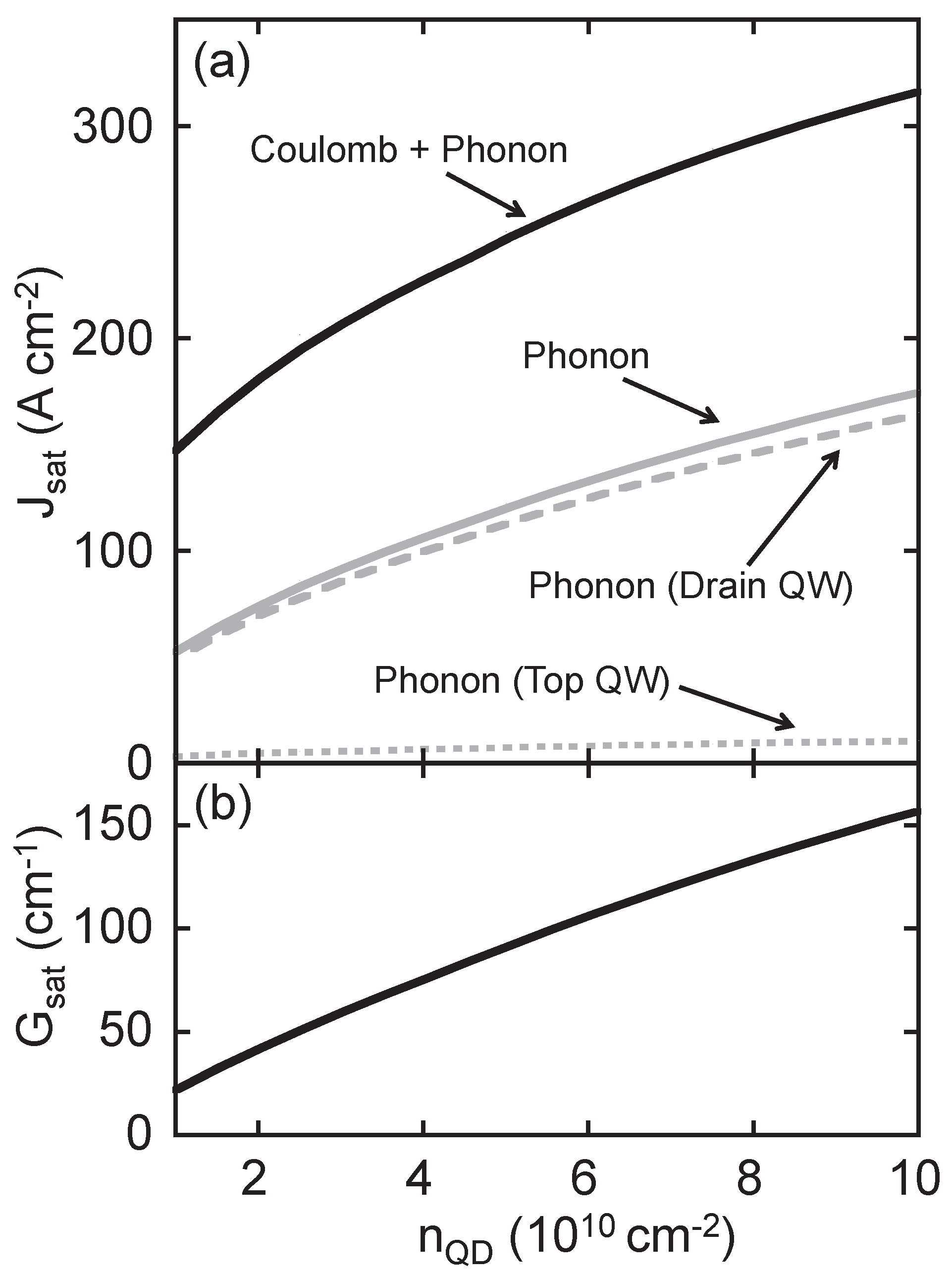
3.2. Contributions to the Current
4. Conclusions
Acknowledgments
Author Contributions
Conflicts of Interest
References
- Faist, J.; Capasso, F.; Sivco, D.L.; Sirtori, C.; Hutchinson, A.L.; Cho, A.Y. Quantum cascade laser. Science 1994, 264, 553–556. [Google Scholar] [CrossRef] [PubMed]
- Gmachl, C.; Capasso, F.; Sivco, D.L.; Cho, A.Y. Recent progress in quantum cascade lasers and applications. Rep. Prog. Phys. 2001, 64, 1533–1601. [Google Scholar] [CrossRef]
- Bai, Y.; Slivken, S.; Kuboya, S.; Darvish, S.R.; Razeghi, M. Quantum cascade lasers that emit more light than heat. Nat. Photonics 2010, 4, 99–102. [Google Scholar] [CrossRef]
- Yao, Y.; Hoffman, A.J.; Gmachl, C.F. Mid-infrared quantum cascade lasers. Nat. Photonics 2012, 6, 432–439. [Google Scholar] [CrossRef]
- Iotti, R.C.; Rossi, F. Nature of charge transport in quantum-cascade lasers. Phys. Rev. Lett. 2001, 87, 146603. [Google Scholar] [CrossRef] [PubMed]
- Indjin, D.; Harrison, P.; Kelsall, R.; Ikonic, Z. Electron transport in GaAs/AlGaAs quantum cascade lasers operating in midinfrared is calculated self-consistently using an intersubband scattering model. Appl. Phys. Lett. 2002, 91, 9019–9026. [Google Scholar]
- Waldmueller, I.; Wanke, M.C.; Lerttamrab, M.; Allen, D.G.; Chow, W.W. Inverse-quantum-engineering: A new methodology for designing quantum cascade lasers. IEEE J. Quant. Electron. 2010, 46, 1414–1420. [Google Scholar] [CrossRef]
- Waldmueller, I.; Wanke, M.C.; Chow, W.W. Circumventing the Manley-Rowe quantum efficiency limit in an optically pumped terahertz quantum-cascade amplifier. Phys. Rev. Lett. 2007, 99, 117401. [Google Scholar] [CrossRef] [PubMed]
- Bai, Y.; Darvish, S.R.; Slivken, S.; Zhang, W.; Evans, A.; Nguyen, J.; Razeghi, M. Room temperature continuous wave operation of quantum cascade lasers with watt-level optical power. Appl. Phys. Lett. 2008, 92, 101105. [Google Scholar] [CrossRef]
- Faist, J.; Capasso, F.; Sirtori, C.; Sivco, D.L.; Baillargeon, J.N.; Hutchinson, A.L.; Chu, S.N.G.; Cho, A.Y. High power mid-infrared (λ ∼ 5 µm) quantum cascade lasers operating above room temperature. Appl. Phys. Lett. 1996, 68, 3680–3682. [Google Scholar] [CrossRef]
- Page, H.; Becker, C.; Robertson, A.; Glastre, G.; Ortiz, V.; Sirtori, C. 300 K operation of a GaAs-based quantum-cascade laser at λ ∼ 9 µm. Appl. Phys. Lett. 2001, 78, 3529–3531. [Google Scholar] [CrossRef]
- Slivken, S.; Evans, A.; Zhang, W.; Razeghi, M. High-power, continuous-operation intersubband laser for wavelengths greater than 10 µm. Appl. Phys. Lett. 2007, 90, 151115. [Google Scholar] [CrossRef]
- Grange, T. Nanowire terahertz quantum cascade lasers. Appl. Phys. Lett. 2014, 105, 141105. [Google Scholar] [CrossRef]
- Grange, T. Electron transport in quantum wire superlattices. Phys. Rev. B 2014, 89, 165310. [Google Scholar] [CrossRef]
- Wingreen, N.S.; Stafford, C.A. Quantum-dot cascade laser: Proposal for an ultralow-threshold semiconductor laser. IEEE J. Quant. Electron. 1997, 33, 1170–1173. [Google Scholar] [CrossRef]
- Hsu, C.F.; O, J.S.; Zory, P.; Botez, D. Intersubband quantum-box semiconductor lasers. IEEE J. Sel. Top. Quant. Electron. 2000, 6, 491–503. [Google Scholar]
- Liu, G.; Stintz, A.; Li, H.; Malloy, K.; Lester, L. Extremely low room-temperature threshold current density diode lasers using InAs dots in In0.15Ga0.85As quantum well. Electron. Lett. 1999, 35, 1163–1165. [Google Scholar] [CrossRef]
- Zhukov, A.E.; Kovsh, A.R.; Ustinov, V.M.; Shernyakov, Y.M.; Mikhrin, S.S.; Maleev, N.A.; Kondrat’eva, E.Y.; Livshits, D.A.; Maximov, M.V.; Volovik, B.V.; et al. Continuous-wave operation of long-wavelength quantum-dot diode laser on a GaAs substrate. IEEE Photonics Technol. Lett. 1999, 11, 1345–1347. [Google Scholar] [CrossRef]
- Deppe, D.; Shavritranuruk, K.; Ozgur, G.; Chen, H.; Freisem, S. Quantum dot laser diode with low threshold and low internal loss. Electron. Lett. 2009, 45, 54–56. [Google Scholar] [CrossRef]
- Cheng, Y.; Wu, J.; Zhao, L.; Luo, X.; Wang, Q.J. Ground-state lasing in high-power InAs/GaAs quantum dots-in-a-well laser using active multimode interference structure. Opt. Lett. 2015, 40, 69–72. [Google Scholar] [CrossRef] [PubMed]
- Pan, D.; Towe, E.; Kennerly, S. Normal-incidence intersubband (In, Ga)As/GaAs quantum dot infrared photodetectors. Appl. Phys. Lett. 1998, 73, 1937–1939. [Google Scholar] [CrossRef]
- Zhang, W.; Lim, H.; Taguchi, M.; Tsao, S.; Movaghar, B.; Razeghi, M. High-detectivity InAs quantum-dot infrared photodetectors grown on InP by metal-organic chemical-vapor deposition. Appl. Phys. Lett. 2005, 86, 191103. [Google Scholar] [CrossRef]
- Schrey, F.F.; Rebohle, L.; Müller, T.; Strasser, G.; Unterrainer, K.; Nguyen, D.P.; Regnault, N.; Ferreira, R.; Bastard, G. Intraband transitions in quantum dot-superlattice heterostructures. Phys. Rev. B 2005, 72, 155310. [Google Scholar] [CrossRef]
- Ulbrich, N.; Bauer, J.; Scarpa, G.; Boy, R.; Schuh, D.; Abstreiter, G.; Schmult, S.; Wegscheider, W. Midinfrared intraband electroluminescence from AllnAs quantum dots. Appl. Phys. Lett. 2003, 83, 1530–1532. [Google Scholar] [CrossRef]
- Anders, S.; Rebohle, L.; Schrey, F.F.; Schrenk, W.; Unterrainer, K.; Strasser, G. Electroluminescence of a quantum dot cascade structure. Appl. Phys. Lett. 2003, 82, 3862–3864. [Google Scholar] [CrossRef]
- Zhuo, N.; Liu, F.; Zhang, J.; Wang, L.; Liu, J.; Zhai, S.; Wang, Z. Quantum dot cascade laser. Nanoscale Res. Lett. 2014, 9, 1–7. [Google Scholar] [CrossRef] [PubMed]
- Wasserman, D.; Ribaudo, T.; Lyon, S.A.; Lyo, S.K.; Shaner, E.A. Room temperature midinfrared electroluminescence from InAs quantum dots. Appl. Phys. Lett. 2009, 94, 061101. [Google Scholar] [CrossRef]
- Hochreiner, A.; Schwarzl, T.; Eibelhuber, M.; Heiss, W.; Springholz, G.; Kolkovsky, V.; Karczewski, G.; Wojtowicz, T. Midinfrared electroluminescence from PbTe/CdTe quantum dot light-emitting diodes. Appl. Phys. Lett. 2011, 98, 021106. [Google Scholar] [CrossRef]
- Michael, S.; Chow, W.W.; Schneider, H.C. Microscopic model for intersubband gain from electrically pumped quantum-dot structures. Phys. Rev. B 2014, 90, 165302. [Google Scholar] [CrossRef]
- Michael, S.; Chow, W.W.; Schneider, H.C. Quantum dots as active material for quantum cascade lasers: Comparison to quantum wells. Proc. SPIE 2016, 9767. [Google Scholar] [CrossRef]
- Chow, W.W.; Jahnke, F. On the physics of semiconductor quantum dots for applications in lasers and quantum optics. Prog. Quant. Electron. 2013, 37, 109–184. [Google Scholar] [CrossRef]
- Burnett, B.A.; Williams, B.S. Density matrix model for polarons in a terahertz quantum dot cascade laser. Phys. Rev. B 2014, 90, 155309. [Google Scholar] [CrossRef]
- Nextnano3. Available online: http://www.nextnano.de/nextnano3/ (accessed on 7 May 2016).
- Florian, M.; Gies, C.; Jahnke, F.; Leymann, H.A.; Wiersig, J. Equation-of-motion technique for finite-size quantum-dot systems: Cluster expansion method. Phys. Rev. B 2013, 87, 165306. [Google Scholar] [CrossRef]
- Bhattacharya, R.; Pal, B.; Bansal, B. On conversion of luminescence into absorption and the van Roosbroeck-Shockley relation. Appl. Phys. Lett. 2012, 100, 222103. [Google Scholar] [CrossRef]


© 2016 by the authors; licensee MDPI, Basel, Switzerland. This article is an open access article distributed under the terms and conditions of the Creative Commons Attribution (CC-BY) license (http://creativecommons.org/licenses/by/4.0/).
Share and Cite
Michael, S.; Chow, W.W.; Schneider, H.C. Mid-Infrared Quantum-Dot Quantum Cascade Laser: A Theoretical Feasibility Study. Photonics 2016, 3, 29. https://doi.org/10.3390/photonics3020029
Michael S, Chow WW, Schneider HC. Mid-Infrared Quantum-Dot Quantum Cascade Laser: A Theoretical Feasibility Study. Photonics. 2016; 3(2):29. https://doi.org/10.3390/photonics3020029
Chicago/Turabian StyleMichael, Stephan, Weng W. Chow, and Hans Christian Schneider. 2016. "Mid-Infrared Quantum-Dot Quantum Cascade Laser: A Theoretical Feasibility Study" Photonics 3, no. 2: 29. https://doi.org/10.3390/photonics3020029
APA StyleMichael, S., Chow, W. W., & Schneider, H. C. (2016). Mid-Infrared Quantum-Dot Quantum Cascade Laser: A Theoretical Feasibility Study. Photonics, 3(2), 29. https://doi.org/10.3390/photonics3020029