Article

Mid-Infrared Quantum-Dot Quantum Cascade Laser: A Theoretical Feasibility Study

by
Stephan Michael
1,
Weng W. Chow
2 and
Hans Christian Schneider
1,*
1
Department of Physics and Research Center OPTIMAS, University of Kaiserslautern, P.O. Box 3049, 67653 Kaiserslautern, Germany
2
Semiconductor Materials and Device Sciences Department, Sandia National Laboratories, Albuquerque, NM 87185-1086, USA
*
Author to whom correspondence should be addressed.
Photonics 2016, 3(2), 29; https://doi.org/10.3390/photonics3020029
Submission received: 31 March 2016 / Revised: 6 May 2016 / Accepted: 9 May 2016 / Published: 13 May 2016
(This article belongs to the Special Issue Quantum Cascade Lasers - Advances and New Applications)

Abstract

:
In the framework of a microscopic model for intersubband gain from electrically pumped quantum-dot structures we investigate electrically pumped quantum-dots as active material for a mid-infrared quantum cascade laser. Our previous calculations have indicated that these structures could operate with reduced threshold current densities while also achieving a modal gain comparable to that of quantum well active materials. Here, we study the influence of two important quantum-dot material parameters, namely inhomogeneous broadening and quantum-dot sheet density, on the performance of a proposed quantum cascade laser design. In terms of achieving a positive modal net gain, a high quantum-dot density can compensate for moderately high inhomogeneous broadening, but at a cost of increased threshold current density. However, by minimizing quantum-dot density with presently achievable inhomogeneous broadening and total losses, significantly lower threshold densities than those reported in quantum-well quantum-cascade lasers are predicted by our theory.

Graphical Abstract

1. Introduction

Quantum cascade lasers (QCL) based on quantum wells (QW) have been an exciting and important topic of optoelectronic-device research for decades [1,2,3,4,5,6,7,8]. These systems have been realized up to and above room temperature and with high output powers [9,10,11]. Also, continuous operation with high efficiency has been achieved at wavelengths greater than 10 µm [12].
Using low-dimensional systems such as quantum dots (QDs) instead of QWs in QCLs promises a reduction of non-radiative losses due to their different density of states. In addition to QDs, nanowires have also been studied in this context theoretically recently [13,14]. Early proposals with QDs [15] involved transitions between QDs in different layers, but the idea of using transitions inside a single QD was already suggested in Reference [16]. Later it was shown experimentally that QDs in general promise lower threshold currents than conventional laser diodes [17,18,19,20]. Recently, much experimental progress in the direction of QD intersublevel devices has been made with mid-infrared (mid-IR) photodetectors [21,22,23]. While mid-IR electroluminescence at low temperatures [24,25,26], and also at room temperature [27,28] have been demonstrated, no QD-QCLs operating at room temperature have been realized so far.
In order to advance the understanding of the processes in QDs that are important for their use as a gain material for a QCL, we have used the design of the experimental structure of Reference [27], which has shown mid-IR electroluminescence, as a guide to develop a model QCL active region consisting of QDs. In particular, we have proposed a dot-in-a-well QD structure (DWELL structure) sandwiched between QWs, i.e., a QW-QD-QW structure [29,30].
The particular features of the model used to describe the QW-QD-QW structure are that it incorporates continuum states including tunneling with QD states, as well as polaronic effects, which effectively broaden the discrete QD states [31], and thus goes beyond earlier proposals of QDs as active material for QCLs [15,16]. The detailed inclusion of scattering contributions at elevated densities, at which continuum states are involved, also sets our approach apart from studies of strong electron-phonon coupling effects, such as long-lived QD polarons [32]. In Reference [29] we discussed theoretically requirements for an optimal line-up of QW and QD states in the QW-QD-QW structure. We found that it was most important to have an efficient extraction of carriers from the QW-QD-QW system by an additional collector structure. Otherwise electrons pile up in continuum states and provide an Auger-like contribution that degrades the performance, as we discuss in some detail below. A model for the design of the collector region, however, is beyond the scope of the present paper. Using our optimized band line-up for the active region in combination with our efficient extraction process, we found a reduced current requirement to achieve a gain-length product comparable to that of mid-IR QW QCL devices, for an inhomogeneous broadening of a quantum-dot ensemble that is close to the lower limit achievable today using self-organized growth [30].
The present paper extends our previous studies [29,30] and investigates how the inhomogeneous broadening and QD density affect the performance of QDs as active material for mid-IR QCL devices. We do not address here the numerous technical challenges of fabricating a QD laser device that fulfills our model requirements (in particular, the precise band line-up and a collector region with the desired properties), but focus on the tradeoffs among influences of the QD material parameters, which are an important part of design of possible future mid-IR QD QCL devices.
The paper is organized as follows. In Section 2, we introduce our theoretical model and indicate how we calculate the modal gain and the different contributions to the current. In Section 3 we first present calculated results of our optimized QD QCL model. We apply these to a feasibility study using QD density and inhomogeneous broadening as parameters. As the different scattering pathways through the QD active region have an important influence on the performance, we also analyze the different contributions to the current in some detail.

2. Setup

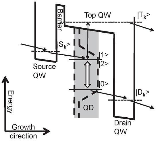
The model system of a QD structure as a gain material for QCLs that we investigate here was introduced in Reference [29], where the material composition and geometry have been optimized. Here, we give only a brief description. Figure 1 shows a schematic picture of the investigated structure, which is patterned after the experimental device in Reference [27]. The periodic QD QCL structure with device periodicity of 50 nm in Figure 1 (left) consists of alternating active and collector regions. The active region shown in the enlarged band lineup in Figure 1 (right) is described microscopically in our model. Here, a thin active layer of QDs embedded in a QW (DWELL structure) is sandwiched between a source QW, where the carriers are injected into the excited states of the QDs, and a drain QW, where the carriers are extracted from the ground state of the QDs. When a steady-state current is driven through this band lineup it creates an inversion N between the ground and excited QD states, which can be used for the amplification of an optical field. Finally, as the collector region combines the carriers from the top and drain QW, in a periodic structure these carriers can be injected into the following source QW.
The microscopic description of the region depicted in Figure 1 (right) includes a realistic model of the underlying electronic structure [33]. Furthermore, our dynamical model is based on the semiconductor Bloch equations and contains Boltzmann-like electron-phonon and electron-electron scattering terms including polaronic effects with an effective quasi-particle broadening [29]. The latter is especially important for scattering where discrete QD levels are involved. Electrons interact in general with longitudinal acoustic (LA) and optical (LO) phonons, but, as long as the level spacing of the QDs is much larger than the typical energy range of the acoustic phonons coupled to the QDs, the scattering effects due to acoustic phonons are inefficient.
In particular, we describe the occupation of the QD states by ensemble-averaged electron distributions. We do not include carrier correlation effects, as they are important when only a few QDs are coupled to a single cavity mode [34]. However, we do include scattering processes where several electrons in each QD of the ensemble may be involved under current injection.
The electron-phonon scattering contributions can be characterized by the types of states (i.e., QD, QW) involved in the scattering process: The different possibilities are intra-QW scattering (only QW states involved), phonon-assisted QD capture/emission (one QW state involved), and intra-QD scattering (only QD states involved). For the electron-electron scattering contributions we distinguish between intra-QW scattering (only QW states involved), intra-QD scattering (only QD states involved) and Auger-like contributions. Among the Auger-like contributions we count the following processes: QW-assisted QD capture/emission (three QW states involved), QW-assisted QD scattering (transitions between two QW states and two QD states, respectively), pure QD-QW scattering (QD-QW transitions), and QD-assisted QD capture/emission (three QD states involved). More details on the calculation of the electronic structure, the Coulomb- or electron-phonon scattering matrix elements and the derivation of the scattering contributions can be found in Reference [29].
Further, we model the electron injection into the source QW and the extraction of electrons by transport of electrons from the top or drain QW into the collector region with rate equations. We do not address the challenge of growing an optimized design of the collector region for an efficient extraction process and a minimization of carrier losses.
With regard to the injection model, we should also briefly discuss changes introduced to the band lineup in a biased structure. We assume in the following dynamical calculations a structure optimized in the presence of a bias voltage. For an actual device design, the cold structure needs to be optimized so that the bias-induced shift leads to a level lineup close to the one described in Figure 1. For example, we have checked that, for a field of 36 kV/cm, the following material composition leads to the desired level line-up: The DWELL structure itself consists of a GaAs top QW with embedded In 0 . 75 Ga 0 . 25 As QDs, the source-QW composition is In 0 . 19 Ga 0 . 81 As, and that of the drain-QW is In 0 . 33 Ga 0 . 67 As.
These compositions have been computed without many-particle renormalizations of the band structure, but should be meaningful because energy shifts of only a few meVs do not affect the scattering behavior significantly. For instance, the steady-state result for the cw small signal gain should described accurately, if the material parameters of the cold structure are optimized for the applied voltage. However, we cannot resolve the switch-on dynamics during which this renormalized band lineup develops. The inclusion of interaction-induced shifts would be a numerical challenge, as we would have to treat kinetic and spectral properties self-consistently. To go beyond the present results, which neglect many-particle renormalizations, we would have to do inverse quantum engineering for the cold structure, which increases the numerical demand even more.
Our analysis focuses on the active region, but is transferable to a periodic structure (like a QD QCL), if small carrier losses in the collector region are neglected. This is a valid assumption for an optimized design of the collector region. However, finite carrier losses increase with the length of the device and restrict its extension in the direction of current flow, but the current coming from the injector region is not significantly changed. By contrast, the overlaps of the QW and QD wave functions as well as the QD density substantially influence the injected current, and these are incorporated in our microscopic theory. Thus, we compute microscopically the modal gain and current density as a measure for the performance of the active region, and regard inhomogeneous broadening and QD density as parameters. We will assume a temperature of 300 K for all the results presented in this paper.
We calculate the steady-state current density J through the QD QCL device via
J = e 1 A k d n k d t | inj
where ( d n k / d t ) | inj is a measure of the number of injected electrons into the source QW per time and A is the normalization area of the source QW. The steady-state modal gain G can be calculated with the help of the inversion N
G = Γ con 2 ω 0 c 0 ε 0 n b Γ inh n QD μ 2 γ d N
where Γ con = 0 . 65 is the confinement factor, ω 0 = 105 meV is the transition energy, n b = 3 . 4 (GaAs) the background refractive index of the host material, = 50 nm is the periodicity length of the structure, μ = 2 . 5 e nm the dipole moment, γ d = 1 meV the polarization dephasing (see also Reference [29] for the choice of this quantity), n Q D the QD density, and N the inversion of the optically active states. The inhomogeneous broadening, in contrast to the homogeneous broadening determined by the polarization dephasing, acts as an effective reduction Γ inh of the density n Q D of QDs that are resonant with the optical field and is calculated assuming a Gaussian distributed level spacing of the QD ensemble. The microscopic model of the QD active material and the electronic transitions involved are calculated in the transport part of the model, which determines the steady-state inversion and current.
In addition to electron-electron and electron-phonon interaction, spontaneous emission of photons between the optically active states of the QDs might contribute to the current. Therefore, we computed the spontaneous emission current [31] via the equation
J s p = e 0 d ω S ω , α ( ω )
with the spontaneous emission spectrum S ω , α ( ω ) calculated with a nonequilibrium Kubo-Martin-Schwinger relation as given, e.g., in Reference [35] using the absorption coefficient α ( ω ) proportional to the reciprocal periodicity length 1 . Numerically we find that the spontaneous emission current is below 1 A·cm 2 for QD densities up to 5 × 10 11 cm 2 and therefore negligible for the QD model under study.

3. Results

3.1. QD Material Parameters

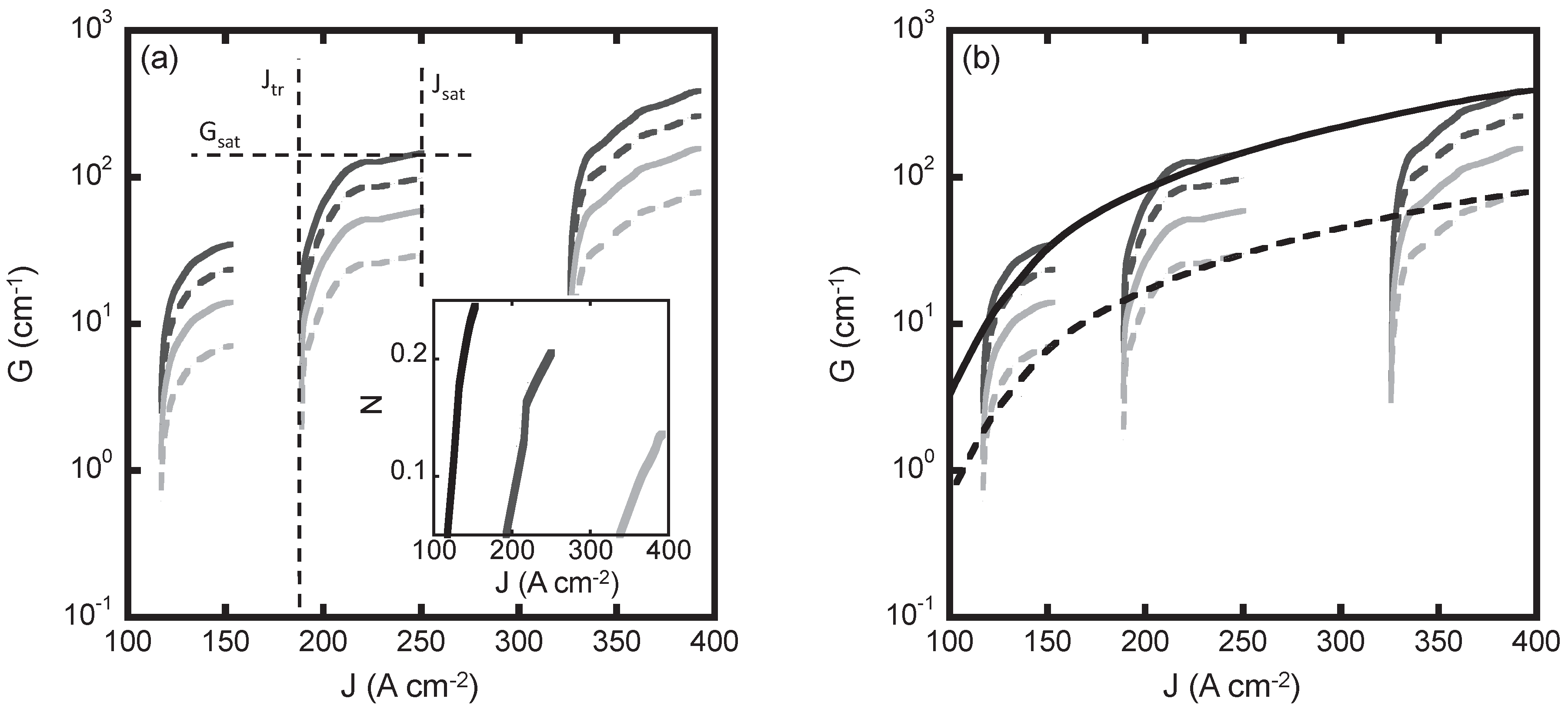
As explained in the previous section, we determine the inversion N vs. current density J by a microscopic model of the steady-state carrier transport from the source QW through the active QD region into the drain QW. Figure 2a shows the results of this calculation for various QD densities n QD in two different forms. While the basic physics contained in Figure 2 has been discussed in our previous papers [29,30], it shows some of the “raw data” needed for the main results of this paper concerning the influence of QD material parameters on QD QCL design choices. Figure 2 shows the modal gain G, which is computed by Equation (2), vs. current density J in the steady state and the inset figure shows the inversion vs. current density J. In our calculation, the inversion is a property of individual QDs, whereas the modal gain applies to the QD ensemble.
We do the transport calculation for a range of injection rates into the source QW, and from this determine the current density. Increasing the injection rate leads to a larger current density J until a saturation value around an injection rate of, e.g., Λ = 1 . 2 ps 1 for moderate QD densities is reached. For a larger current density J, a higher inversion and a higher modal gain result for a specific QD density. Note that, for a lower QD density, a higher inversion for the individual QD transitions may be reached and less current is necessary to obtain this inversion. This can be explained as follows: For higher QD densities more carriers need to go through the active QD layer and thus the steady state current density increases. However, more carriers injected into the whole structure also mean more carrier-carrier and carrier-phonon scattering processes into continuum states, which compete with the transition between the optically active states in the QDs. In particular, the structure is designed so that carrier-phonon scattering causes inversion for the optically active QD states, but the inversion is diminished by an increased effectiveness of carrier-carrier scattering processes at higher carrier densities. In the following we analyze the dependencies between gain G and the density of the QD ensemble n QD in detail.
From Figure 2a, we observe a reduced gain G for a higher inhomogeneous broadening. Most notably, in spite of a reduction of the individual QD inversion N for higher QD densities n QD (as shown in the inset of the Figure 2a), the gain G of the whole QD ensemble is increased. But the increase of the QD density also leads to an increased current requirement.
For the intermediate QD density of n QD = 5 × 10 10 cm 2 , we have also indicated in Figure 2a how we determine the saturated gain G sat and the threshold and saturation currents J tr and J sat , respectively, for a given QD density and inhomogeneous broadening. Figure 2b shows schematically, for two different values of inhomogeneous broadening, how we obtain by interpolation the dependence of G sat on the current J from a set of G vs. J calculations. Using this procedure, we obtain G sat as a function of current, QD density and inhomogeneous broadening.
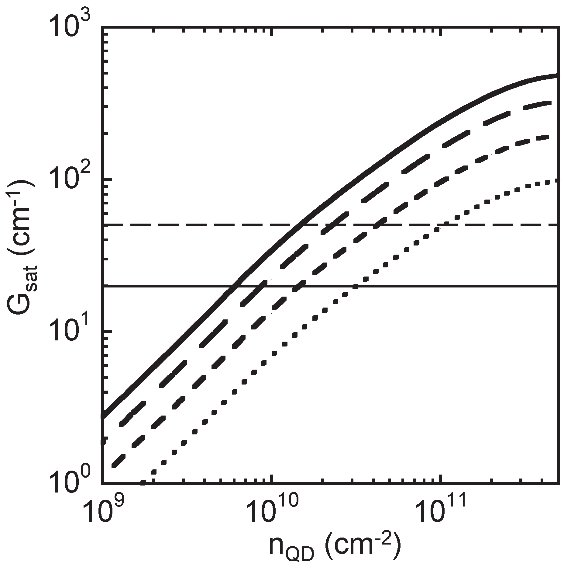
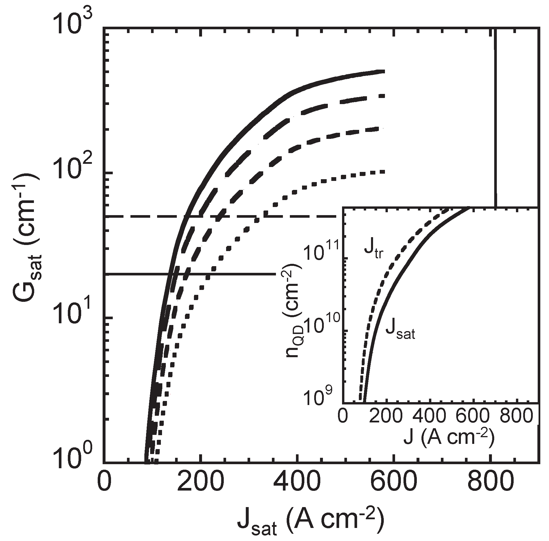
We next plot the saturation gain G sat vs. QD density n QD in Figure 3, and the saturation gain vs. saturation current density J sat in Figure 4 for a set of inhomogeneous broadenings. As the saturation gain depends on both quantities, one could interpret these figures as the two dimensional projections of the three dimensional saturation gain curve G sat ( n QD , J sat ) . We have also included two lines for the loss α, which is a combination of the mirror and waveguide losses. The smaller value α = 20 cm 1 is a conservative estimate taken from Reference [12] as lower currently attainable limit and the larger one α = 50 cm 1 is intended to mimic the effect of a positive net gain of about 30 cm 1 .
Figure 3 shows that, in order to overcome the total losses, the QD density has to be around 1 × 10 10 cm 2 for an inhomogeneous broadening with FWHM Δ inh of 10 meV and at most 1 × 10 11 cm 2 for Δ inh = 50 meV. Figure 4 then shows that this entails a current density J sat of around 150 A·cm 2 for Δ inh = 10 meV, and between 225 A·cm 2 and 325 A·cm 2 for Δ inh = 50 meV. Figure 4 also shows that, for all the QD densities considered here, the current density J sat is below the QW QCL current density limit, which we determined in Reference [30]. Finally, the inset in Figure 4 contains the relation between QD density n QD and the two different current densities J sat and J tr , as defined in Figure 2. There is obviously only a small deviation between transparency and saturation currents, but a pronounced dependence of the current density on the QD density.
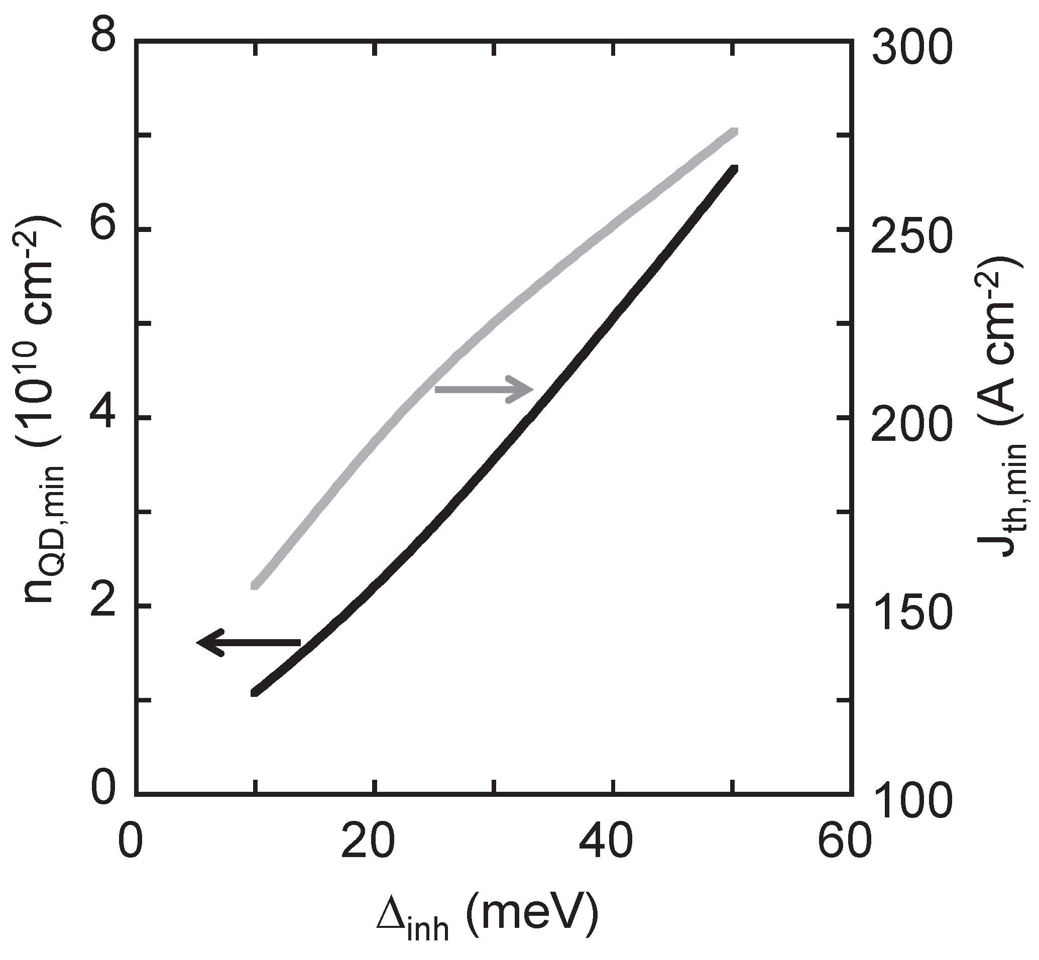
We next pick an intermediate value for the losses α = 35 cm 1 and determine the minimum QD density n QD , min to overcome this losses, i.e., to produce a zero net gain. The corresponding current density is thus the threshold current density for this loss, which we denote by J th , min . Figure 5 plots n QD , min and J th , min vs. the inhomogeneous broadening Δ inh . For small inhomogeneous broadening, a lower QD density is necessary to overcome the losses. Also a lower threshold current is required for small inhomogeneous broadenings, because the threshold current increases with increasing QD density. In particular, for an inhomogeneous broadening with FWHM of 10 meV (50 meV) a minimum QD density of about 1 × 10 10 cm 2 ( 7 × 10 10 cm 2 ) with a corresponding threshold current density of about 150 A·cm 2 (275 A·cm 2 ) is required to overcome the total losses. This figure shows clearly the dependencies between QD material parameters and threshold current for a particular device design, and establishes that net gain for realistic values of QD density and inhomogeneous broadening should be achievable.

3.2. Contributions to the Current

The dynamics behind the results presented so far arise from a complicated interplay of complex electron scattering processes in the whole structure under investigation. To elucidate these processes, we first separate the different contributions to the current. We then explain qualitatively the microscopic scattering processes behind the contributions to the current, as the detailed scattering pathways through the structure have an important influence on the performance. Even for a device design that is different from ours, these qualitative considerations concerning the scattering pathways may help to optimize a structure design.
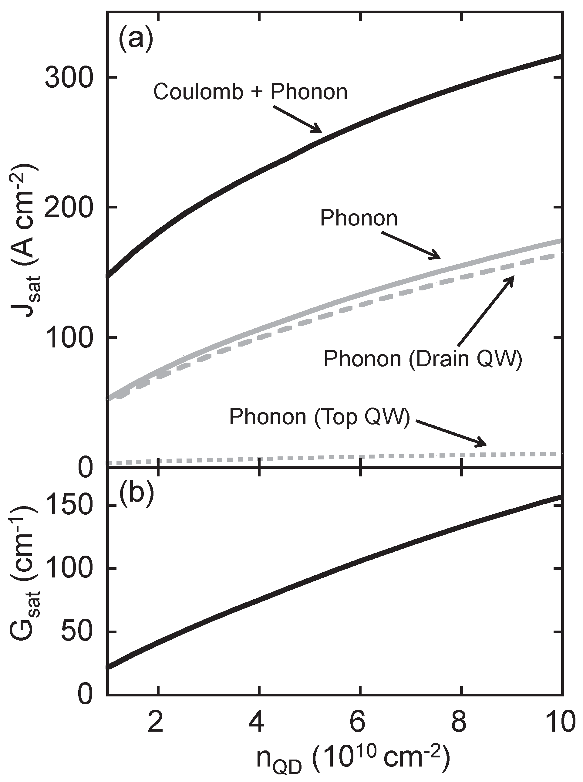
Figure 6a shows the different contributions to the current density, for saturated gain J sat vs. ensemble QD density n QD . The solid line is the full calculation including all scattering mechanisms. The electron-phonon contributions, shown as solid gray line in Figure 6a, is determined in a separate calculation without Coulomb interaction. We interpret as the Coulomb-interaction contribution to the current the difference of the current resulting from a calculation with and without Coulomb-scattering. Compared to the electron-phonon interaction contribution it plays an almost equally important role and primarily depends on the electronic occupation of the continuum states above the QD, as will be discussed in more detail below. For completeness, the saturated gain (corresponding to the current for saturated gain) vs. ensemble QD density is shown in Figure 6b for an inhomogeneous broadening of 15 meV (FWHM).
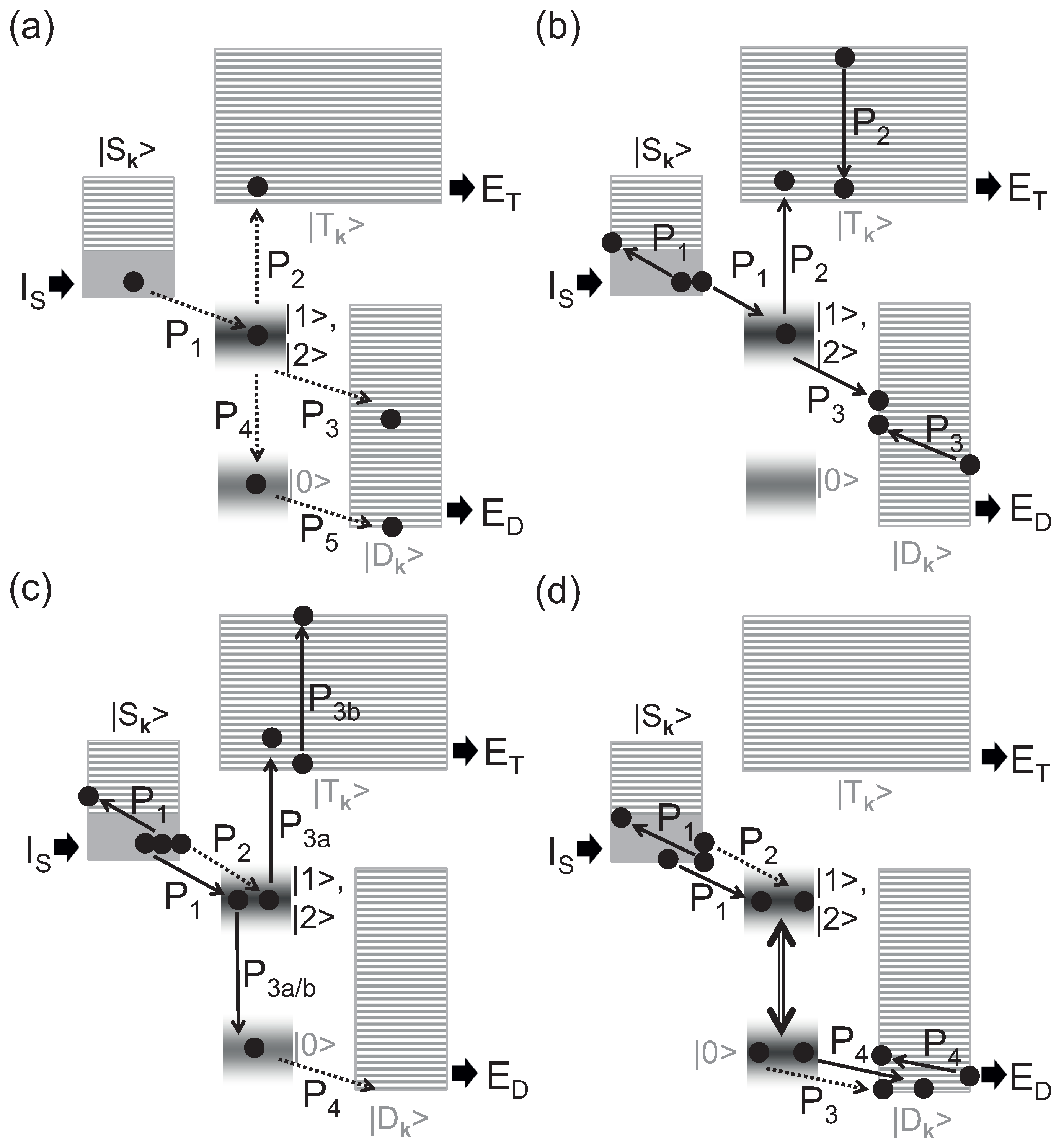
The different results shown in Figure 6a are the best one can do to separate different contributions to the current in the framework of the numerical calculation. Figure 7 contains a purely schematic picture of different scattering pathways that are involved in the computed results shown in Figure 6a. As already mentioned, the spontaneous emission current is negligible for the QD model under study. In Figure 7a–d, the steady-state current injected into the source QW ( I S ) is equal to the current extracted from the drain ( E D ) and the top QW ( E T ).
To distinguish between different electron-phonon contributions, which are the gray curves in Figure 6a, we turn first to Figure 7a. In the vast majority of current pathways, the electrons relax from the source QW to the excited QD states via phonon-assisted QD capture ( P 1 ). Then, the electron may contribute via direct phonon-assisted QD emission from the excited QD to the top QW states ( P 2 ) to the current extracted from the top QW (see dotted gray line in Figure 6a). Another possibility is an electron-phonon process via direct phonon-assisted QD emission from excited QD into drain QW states ( P 3 ). Also, the combination of the intra-QD relaxation process P 4 and the phonon-assisted QD emission process P 5 , i.e., indirect electron-phonon scattering (from the ground QD) to drain QW states primarily due to a weakening of the phonon-bottleneck effect by the inclusion of polaronic effects, might occur. The scattering processes P 3 and P 4 + 5 contribute to the current extracted from the drain QW (see dashed gray line in Figure 6a).
Next, we describe the Coulomb processes in more detail: First, Figure 7b depicts QW-assisted QD capture/emission counted among Auger-like processes, i.e., processes where QD and QW states are involved. Furthermore, the scattering pathways (QD-assisted QD emission P 3 a and top QW-assisted QD scattering P 3 b ) illustrated in Figure 7c) make Coulomb-assisted electronic scattering in the QD faster and thus work against the inversion in the QD. In particular, an efficient scattering via top QW-assisted QD scattering P 3 b in Figure 7c requires a pronounced occupation of the continuum states. Finally, in Figure 7d scattering pathways that contribute to the inversion of the optically active states are depicted. Here, the Coulomb processes, source QW-assisted QD capture P 1 and drain QW-assisted QD emission P 4 , support the electron-phonon scattering pathways, phonon-assisted QD capture P 2 and phonon-assisted QD emission P 3 , respectively. The suppression of processes such as top QW-assisted QD scattering P 3 b in Figure 7c is, in fact, detrimental for achieving gain. This was realized earlier [29], and is the reason that the model design includes an extraction process in the top QW to prevent an excessive accumulation of carriers in the top QW. Only the carrier density in the continuum states that piles up despite the extraction process contributes to an Auger-like current that works against the inversion.

4. Conclusions

In conclusion, we presented a theoretical investigation on the influence of QD material properties, such as inhomogeneous broadening and QD density, on the performance of QD active regions for mid-IR QCL devices under room temperature conditions. We computed modal gain and current density and showed that they are strongly influenced by the interdependence between inhomogeneous broadening and QD density. By computing the threshold current we showed how QD density and inhomogeneous broadening influences QD QCL characteristics, which may be used in the future for an optimized design of those devices. More precisely, one can compensate for moderately high inhomogeneous broadening (up to Δ inh = 50 meV) by increasing QD density, but current densities as high as 225 or 325 A·cm 2 will be necessary to achieve positive modal net gain. The direction to take may be to reduce inhomogeneous broadening. Our theory shows that with Δ inh = 15 meV a positive modal net gain is possible with current densities as low as 150 A·cm 2 .
We further investigated the different contributions to the current and found that both Coulomb (i.e., Auger-processes) and electron-phonon scattering play almost equally important roles. As the Coulomb contribution is controlled by the accumulation of carriers in the scattering states of the QD structure, this underscores the importance of QD structure design that allows for an efficient extraction of delocalized carriers in the QD layer.
An experimental realization of the structure proposed and analyzed here would have to produce the energy level line-up rather precisely in a superlattice structure and, perhaps even more importantly, would have to realize a collector region with the design requirements. The combination of these features may present considerable technical challenges associated with QD growth, but we believe our results make a strong case for the feasibility of a QD-QCL, and may help in the design of future mid-IR QD QCL devices.

Acknowledgments

Sandia National Laboratories is a multi-program laboratory managed and operated by Sandia Corporation, a wholly owned subsidiary of Lockheed Martin Corporation, for the U.S. Department of Energy’s National Nuclear Security Administration under contract DE-AC04-94AL85000.

Author Contributions

W.W.C, S.M. and H.C.S. designed the QD QCL device study; S.M. developed and implemented the QD QCL model. S.M. and H.C.S wrote the paper with input from W.W.C.

Conflicts of Interest

The authors declare no conflict of interest.

References

  1. Faist, J.; Capasso, F.; Sivco, D.L.; Sirtori, C.; Hutchinson, A.L.; Cho, A.Y. Quantum cascade laser. Science 1994, 264, 553–556. [Google Scholar] [CrossRef] [PubMed]
  2. Gmachl, C.; Capasso, F.; Sivco, D.L.; Cho, A.Y. Recent progress in quantum cascade lasers and applications. Rep. Prog. Phys. 2001, 64, 1533–1601. [Google Scholar] [CrossRef]
  3. Bai, Y.; Slivken, S.; Kuboya, S.; Darvish, S.R.; Razeghi, M. Quantum cascade lasers that emit more light than heat. Nat. Photonics 2010, 4, 99–102. [Google Scholar] [CrossRef]
  4. Yao, Y.; Hoffman, A.J.; Gmachl, C.F. Mid-infrared quantum cascade lasers. Nat. Photonics 2012, 6, 432–439. [Google Scholar] [CrossRef]
  5. Iotti, R.C.; Rossi, F. Nature of charge transport in quantum-cascade lasers. Phys. Rev. Lett. 2001, 87, 146603. [Google Scholar] [CrossRef] [PubMed]
  6. Indjin, D.; Harrison, P.; Kelsall, R.; Ikonic, Z. Electron transport in GaAs/AlGaAs quantum cascade lasers operating in midinfrared is calculated self-consistently using an intersubband scattering model. Appl. Phys. Lett. 2002, 91, 9019–9026. [Google Scholar]
  7. Waldmueller, I.; Wanke, M.C.; Lerttamrab, M.; Allen, D.G.; Chow, W.W. Inverse-quantum-engineering: A new methodology for designing quantum cascade lasers. IEEE J. Quant. Electron. 2010, 46, 1414–1420. [Google Scholar] [CrossRef]
  8. Waldmueller, I.; Wanke, M.C.; Chow, W.W. Circumventing the Manley-Rowe quantum efficiency limit in an optically pumped terahertz quantum-cascade amplifier. Phys. Rev. Lett. 2007, 99, 117401. [Google Scholar] [CrossRef] [PubMed]
  9. Bai, Y.; Darvish, S.R.; Slivken, S.; Zhang, W.; Evans, A.; Nguyen, J.; Razeghi, M. Room temperature continuous wave operation of quantum cascade lasers with watt-level optical power. Appl. Phys. Lett. 2008, 92, 101105. [Google Scholar] [CrossRef]
  10. Faist, J.; Capasso, F.; Sirtori, C.; Sivco, D.L.; Baillargeon, J.N.; Hutchinson, A.L.; Chu, S.N.G.; Cho, A.Y. High power mid-infrared (λ ∼ 5 µm) quantum cascade lasers operating above room temperature. Appl. Phys. Lett. 1996, 68, 3680–3682. [Google Scholar] [CrossRef]
  11. Page, H.; Becker, C.; Robertson, A.; Glastre, G.; Ortiz, V.; Sirtori, C. 300 K operation of a GaAs-based quantum-cascade laser at λ ∼ 9 µm. Appl. Phys. Lett. 2001, 78, 3529–3531. [Google Scholar] [CrossRef]
  12. Slivken, S.; Evans, A.; Zhang, W.; Razeghi, M. High-power, continuous-operation intersubband laser for wavelengths greater than 10 µm. Appl. Phys. Lett. 2007, 90, 151115. [Google Scholar] [CrossRef]
  13. Grange, T. Nanowire terahertz quantum cascade lasers. Appl. Phys. Lett. 2014, 105, 141105. [Google Scholar] [CrossRef] [Green Version]
  14. Grange, T. Electron transport in quantum wire superlattices. Phys. Rev. B 2014, 89, 165310. [Google Scholar] [CrossRef]
  15. Wingreen, N.S.; Stafford, C.A. Quantum-dot cascade laser: Proposal for an ultralow-threshold semiconductor laser. IEEE J. Quant. Electron. 1997, 33, 1170–1173. [Google Scholar] [CrossRef]
  16. Hsu, C.F.; O, J.S.; Zory, P.; Botez, D. Intersubband quantum-box semiconductor lasers. IEEE J. Sel. Top. Quant. Electron. 2000, 6, 491–503. [Google Scholar]
  17. Liu, G.; Stintz, A.; Li, H.; Malloy, K.; Lester, L. Extremely low room-temperature threshold current density diode lasers using InAs dots in In0.15Ga0.85As quantum well. Electron. Lett. 1999, 35, 1163–1165. [Google Scholar] [CrossRef]
  18. Zhukov, A.E.; Kovsh, A.R.; Ustinov, V.M.; Shernyakov, Y.M.; Mikhrin, S.S.; Maleev, N.A.; Kondrat’eva, E.Y.; Livshits, D.A.; Maximov, M.V.; Volovik, B.V.; et al. Continuous-wave operation of long-wavelength quantum-dot diode laser on a GaAs substrate. IEEE Photonics Technol. Lett. 1999, 11, 1345–1347. [Google Scholar] [CrossRef]
  19. Deppe, D.; Shavritranuruk, K.; Ozgur, G.; Chen, H.; Freisem, S. Quantum dot laser diode with low threshold and low internal loss. Electron. Lett. 2009, 45, 54–56. [Google Scholar] [CrossRef]
  20. Cheng, Y.; Wu, J.; Zhao, L.; Luo, X.; Wang, Q.J. Ground-state lasing in high-power InAs/GaAs quantum dots-in-a-well laser using active multimode interference structure. Opt. Lett. 2015, 40, 69–72. [Google Scholar] [CrossRef] [PubMed]
  21. Pan, D.; Towe, E.; Kennerly, S. Normal-incidence intersubband (In, Ga)As/GaAs quantum dot infrared photodetectors. Appl. Phys. Lett. 1998, 73, 1937–1939. [Google Scholar] [CrossRef]
  22. Zhang, W.; Lim, H.; Taguchi, M.; Tsao, S.; Movaghar, B.; Razeghi, M. High-detectivity InAs quantum-dot infrared photodetectors grown on InP by metal-organic chemical-vapor deposition. Appl. Phys. Lett. 2005, 86, 191103. [Google Scholar] [CrossRef]
  23. Schrey, F.F.; Rebohle, L.; Müller, T.; Strasser, G.; Unterrainer, K.; Nguyen, D.P.; Regnault, N.; Ferreira, R.; Bastard, G. Intraband transitions in quantum dot-superlattice heterostructures. Phys. Rev. B 2005, 72, 155310. [Google Scholar] [CrossRef]
  24. Ulbrich, N.; Bauer, J.; Scarpa, G.; Boy, R.; Schuh, D.; Abstreiter, G.; Schmult, S.; Wegscheider, W. Midinfrared intraband electroluminescence from AllnAs quantum dots. Appl. Phys. Lett. 2003, 83, 1530–1532. [Google Scholar] [CrossRef]
  25. Anders, S.; Rebohle, L.; Schrey, F.F.; Schrenk, W.; Unterrainer, K.; Strasser, G. Electroluminescence of a quantum dot cascade structure. Appl. Phys. Lett. 2003, 82, 3862–3864. [Google Scholar] [CrossRef]
  26. Zhuo, N.; Liu, F.; Zhang, J.; Wang, L.; Liu, J.; Zhai, S.; Wang, Z. Quantum dot cascade laser. Nanoscale Res. Lett. 2014, 9, 1–7. [Google Scholar] [CrossRef] [PubMed]
  27. Wasserman, D.; Ribaudo, T.; Lyon, S.A.; Lyo, S.K.; Shaner, E.A. Room temperature midinfrared electroluminescence from InAs quantum dots. Appl. Phys. Lett. 2009, 94, 061101. [Google Scholar] [CrossRef]
  28. Hochreiner, A.; Schwarzl, T.; Eibelhuber, M.; Heiss, W.; Springholz, G.; Kolkovsky, V.; Karczewski, G.; Wojtowicz, T. Midinfrared electroluminescence from PbTe/CdTe quantum dot light-emitting diodes. Appl. Phys. Lett. 2011, 98, 021106. [Google Scholar] [CrossRef]
  29. Michael, S.; Chow, W.W.; Schneider, H.C. Microscopic model for intersubband gain from electrically pumped quantum-dot structures. Phys. Rev. B 2014, 90, 165302. [Google Scholar] [CrossRef]
  30. Michael, S.; Chow, W.W.; Schneider, H.C. Quantum dots as active material for quantum cascade lasers: Comparison to quantum wells. Proc. SPIE 2016, 9767. [Google Scholar] [CrossRef]
  31. Chow, W.W.; Jahnke, F. On the physics of semiconductor quantum dots for applications in lasers and quantum optics. Prog. Quant. Electron. 2013, 37, 109–184. [Google Scholar] [CrossRef]
  32. Burnett, B.A.; Williams, B.S. Density matrix model for polarons in a terahertz quantum dot cascade laser. Phys. Rev. B 2014, 90, 155309. [Google Scholar] [CrossRef]
  33. Nextnano3. Available online: http://www.nextnano.de/nextnano3/ (accessed on 7 May 2016).
  34. Florian, M.; Gies, C.; Jahnke, F.; Leymann, H.A.; Wiersig, J. Equation-of-motion technique for finite-size quantum-dot systems: Cluster expansion method. Phys. Rev. B 2013, 87, 165306. [Google Scholar] [CrossRef]
  35. Bhattacharya, R.; Pal, B.; Bansal, B. On conversion of luminescence into absorption and the van Roosbroeck-Shockley relation. Appl. Phys. Lett. 2012, 100, 222103. [Google Scholar] [CrossRef]
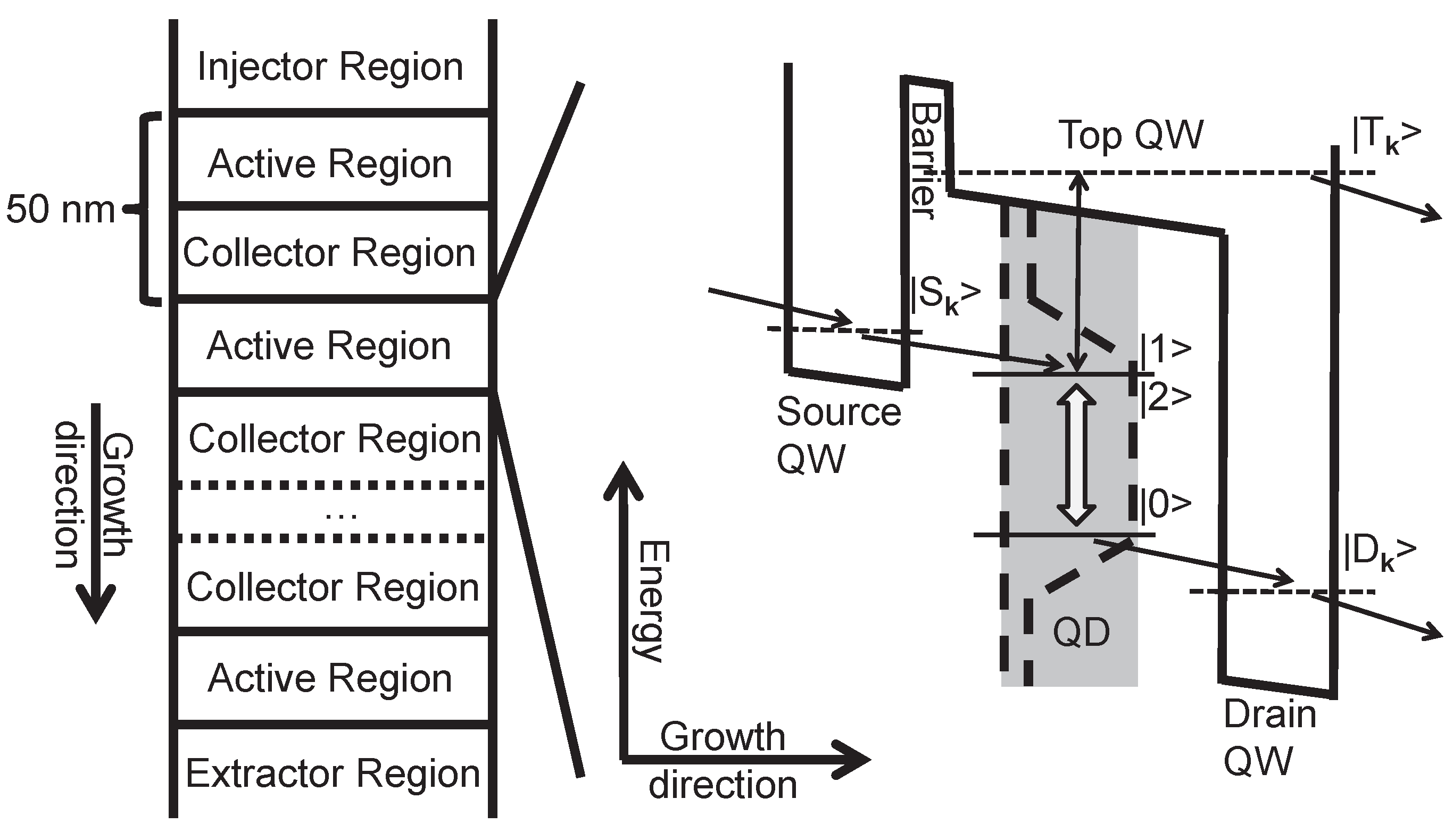
Figure 1. (Left): Schematic diagram of a quantum dot (QD) quantum cascade laser (QCL) structure studied in this paper. The current is injected from an Injector Region into an Active Region and flows in growth direction through a periodic structure of Active and Collector regions until an Extractor Region is reached. The periodicity of the structure is 50 nm. (Right): Model of the active region. The top quantum well (QW) is located energetically above the QD states and the drain QW. The black (double) arrows indicate the pathway of carriers through the active region. The QD transition used for the amplification of an optical field is highlighted by the gray double arrow.
Photonics 03 00029 g001
Figure 2. (a) Modal gain G vs. current density J for QD densities n Q D of n Q D , 1 = 10 10 , n Q D , 2 = 5 × 10 10 and n Q D , 3 = 2 × 10 11 cm 2 . The FWHM of the inhomogeneous broadening Δ inh is 10 (solid dark-gray line), 15 (dashed dark-gray line), 25 (solid light-gray line), and 50 meV (dashed light-gray line). For one data set, the current density J sat for modal saturation gain, the current density J tr for transparency and the modal saturation gain G sat are depicted. Inset: Inversion N vs. current density J for a QD density n QD of 1 × 10 10 cm 2 (black), 5 × 10 10 cm 2 (dark-gray) and 20 × 10 10 cm 2 (light-gray). (b) Saturation gain G sat as function of the current density J sat extracted from raw data as partly shown in Figure 2a for an inhomogeneous broadening with Δ inh of 10 (solid black line) and 50 meV (dashed black line).
Photonics 03 00029 g002
Figure 3. Saturation gain G sat vs. QD density n QD for inhomogeneous broadenings Δ inh of 10 (solid line), 15 (long dashed line), 25 (short dashed line), and 50 meV (dotted line). The black line is the total loss line at 20 cm 1 (solid line) and 50 cm 1 (dashed line).
Photonics 03 00029 g003
Figure 4. Saturation gain G sat vs. current density J sat for inhomogeneous broadenings Δ inh of 10 (solid line), 15 (long dashed line), 25 (short dashed line), and 50 meV (dotted line). The black horizontal line is the total loss line by 20 cm 1 (solid line) and 50 cm 1 (dashed line). The black vertical line is the QW QCL current density limit chosen for comparison. Inset: QD density n QD vs. current density J sat for saturation gain and current density J tr for transparency.
Photonics 03 00029 g004
Figure 5. Minimum QD density n QD , min (black line) and corresponding current density J th , min (gray line) necessary to reach lasing threshold for a device with a total loss of 35 cm 1 vs. inhomogeneous broadening Δ inh .
Photonics 03 00029 g005
Figure 6. (a) Contributions to the current density for saturated gain J sat (solid black line) vs. QD density n QD . The current with (solid black line) and without (solid gray line) inclusion of Coulomb scattering is shown. The current due to electron-phonon scattering consists of the phonon contribution extracted from the drain QW (dashed gray line) and the phonon contribution extracted from the top QW (dotted gray line). (b) Corresponding saturated gain G sat vs. QD density n QD for an inhomogeneous broadening Δ inh of 15 meV.
Photonics 03 00029 g006
Figure 7. Schematic picture of different electronic scattering pathways; in particular, (a) electron-phonon processes, (b) Auger processes, (c) Coulomb induced processes that work against the inversion, and (d) scattering pathways that contribute to gain the cavity field. Electron-phonon scattering is illustrated by one dashed arrow, electron-electron transitions by two solid arrows, and injection or extraction processes by wide arrows. The black QD states and the filled gray QW regions are highly occupied and the gray QD states and the striped gray QW regions have only a small electron occupation. Refer to Figure 1 for the explanation of the states involved.
Photonics 03 00029 g007