1. Introduction
Free space optical (FSO) communication, a cost-effective and highly secured technique using a wide bandwidth on an unregulated spectrum technique, has received growing attention with recent commercialization successes. It is considered an attractive solution to the last mile problem of bridging the gap between the end user and the backbone construction. In regard to the FSO system model, however, a significant influence factor is the turbulence-induced channel fading, which impairs the quality of the received signal and link performance improvement [
1]. Therefore, it is imperative to apply efficient techniques to mitigate the channel fading caused by the atmospheric turbulence. In recent years, many researchers have studied the effects of atmospheric turbulence on FSO communications. A number of turbulence mitigation methods for FSO systems have been proposed, such as diversity techniques, adaptive optical technology, robust modulation techniques,
etc.
Traditionally, modulation schemes, in particular based on intensity modulation/direction detection (IM/DD), for FSO systems have been wildly reported, such as amplitude shift keying (ASK),
etc. However, the performance of the ASK scheme is highly sensitive to the turbulence fluctuation and modulation index; thus, the adaptive detection technique is required at the receiver to improve the link performance [
2,
3]. This would mean the requirement of the knowledge of the channel characteristic, which adds to the system complexity [
3]. Different from IM-based modulation schemes, polarization shift keying (PolSK) was proposed as an alternative modulation technique to both envelop- and phase-based modulation schemes [
4]. Under this technique, information is encoded as different states of polarization (SOPs) of the laser source by an external modulator (
i.e., a Mach–Zehnder modulator) [
5]. For an optical beam, polarization states are the most stable properties compared with the amplitude and phase when propagating though a turbulent channel [
6]. Various PolSK schemes have been proposed for FSO transmission systems [
5,
6,
7]. In [
8], it is shown that the binary PolSK modulation scheme offers improved link performance in terms of the peak optical power by about 3 dB compared to the ASK scheme. However, most of the PolSK schemes proposed so far are based on single user access without interference distortion in the FSO link. In this paper, a novel transceiver architecture based on the PolSK scheme with a multiplexing transmission technique has been proposed to mitigate the channel fading, as well as to enhance the system capacity in FSO communication systems.
Optical code division multiplexing access (OCDMA) is a technology to realize multiplexing transmission and multiple access, which supports high-speed and large capacity communication in optical fiber networks. At the same time, the OCDMA technique has also drawn a lot of attention in optical wireless communications. In [
9], the authors reported for the first time the experimental performance of OCDMA transmission over 160-m FSO links and 20-km optical fiber links, showing that the OCDMA signals can be utilized in an FSO communication system. Furthermore, the use of OCDMA schemes as a countermeasure for the mitigation of turbulence has been considered in [
10,
11], in which the transmission performance of OCDMA signals influenced by atmospheric turbulence and multiple-access interference (MAI) was thoroughly discussed. However, in most of the previous literature [
10,
12,
13], FSO links only can be used to transmit the OCDMA signal based on intensity modulation through free space, and no systematic study of a cost-effective all-optical CDMA-FSO system with external modulation has been carried out. Therefore, such a study will be important in designing and optimizing methods to enhance the performance of the OCDMA FSO systems in operation environments, combining the advantages of high transmission capacity enabled by multiplexing transmission technology and the efficiency of a robust modulation scheme for the mitigation of channel fading.
The advantages of combining PolSK and OCDMA in optical fiber networks were already reported in [
14,
15], where the fiber dispersion and noise are the important impairment factors. However, no complete study providing an analytical model for PolSK-modulated OCDMA systems over an FSO link has been proposed so far to our knowledge. Therefore, the goal of this paper is to analyze and explore the potential of a PolSK-OCDMA FSO system for use in high performance, high speed optical wireless transmission. Firstly, in this paper, we develop a framework for a PolSK-modulated OCDMA signal over a direct detection FSO link modeled by the Gamma-Gamma distribution. Then, we investigate and evaluate the impact of optical scintillation and MAI on the transmission performance of the PolSK-OCDMA FSO link, in terms of the bit error ratio (BER), as well as the outage probability in the case of the plane-wave model. Furthermore, the numerical results show that the transmission performance of the proposed system is highly sensitive to atmospheric turbulence, received optical power and multiple-access interference. For comparison, the OOK and PolSK for the OCDMA-FSO link performance have also been presented. Our theoretical study provides an all-optical CDMA-FSO system structure based on the PolSK scheme, which takes into account the significant influence factors on transmission performance, especially when a large number of active users share the same turbulence channel.
The remainder of the paper is organized as follows. In
Section 2, we introduce the statistical modeling for the atmospheric turbulence. In
Section 3, we present the mathematical modeling for the transmission of the OCMDA signal over the FSO link based on the PolSK modulation. The analytical results are shown and discussed in
Section 4.
Section 5 concludes the paper.
4. Numerical Results and Discussion
In this section, we evaluate the optical scintillation and MAI effects on both the BER and outage probability, taking into account the overall performance of the PolSK-OCDMA signals over the turbulent FSO link. The main simulation parameters used in the numerical calculation are shown in
Table 1.
Since the behavior of the OOK-modulated OCDMA FSO system has already been investigated in several works [
12,
13], we prefer to evaluate the error probability of PolSK modulation to compare it with the OOK scheme under the same OCDMA FSO link conditions. The mathematical model of the error probability for the OOK-based OCDMA FSO system with a fixed threshold has already been evaluated in [
23,
27].
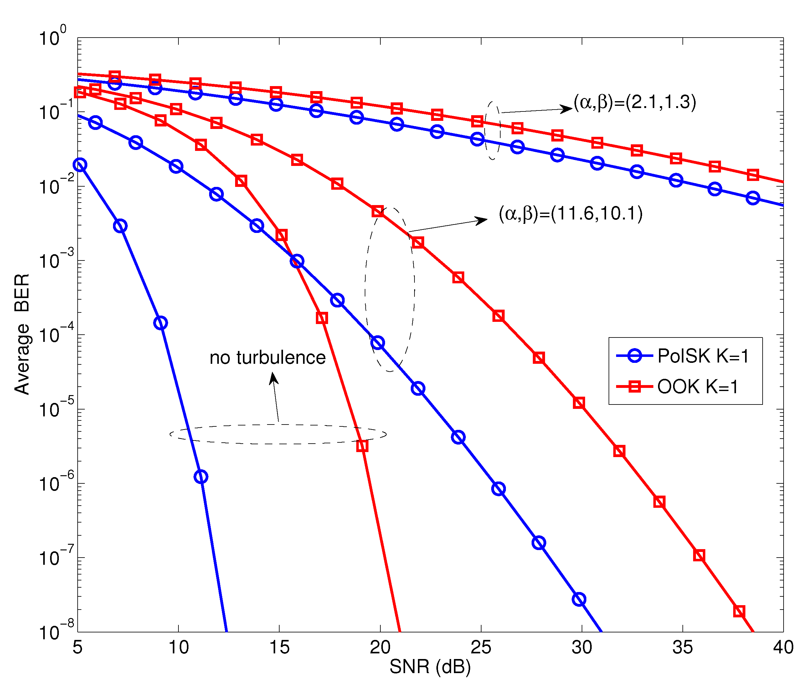
Figure 3 depicts the error probability against the normalized electric SNR for PolSK and OOK (with a fixed threshold of 0.5) schemes in a turbulent OCDMA FSO link when the number of active users
(no multiple-access interference). It is observed that the average BER performance deteriorates with the turbulence level, with OOK displaying the worst case scenario. For a BER of
and scintillation parameters
as a weak turbulent regime, the SNR for PolSK and OOK are about 24.5 dB and 33 dB, respectively. When the scintillation parameters are changed to
as a strong turbulent regime, a lower SNR is required for PolSK compared with OOK at the same average BER level. Therefore, based on these numerical results illustrated in this plot, we can determine that the information encoded in the intensity of the carrier signal is much more prone to turbulence-induced fluctuation. In other words, PolSK offers improved BER performance compared to OOK across all turbulence regimes.
Table 1.
Numerical parameters. PD, photo-detector; PBS, polarization beam splitter; PBC, polarization beam combiner.
Table 1.
Numerical parameters. PD, photo-detector; PBS, polarization beam splitter; PBC, polarization beam combiner.
| Parameters | Value |
|---|
| Link distance L | 1000 m |
| Channel bandwidth B | 2 GHz |
| Operating wavelength λ | 1550 nm |
| Aperture diameter D | 100 mm |
| Coupling losses | 3 dB |
| Beam divergence Θ | ±0.75 rmad |
| Relative intensity noise | −130 dB/Hz |
| Absolute temperature | 300 k |
| PD responsivity ρ | 0.9 A/W |
| Electron charge q | C |
| Noise figure | 2 dB |
| PBS/PBC loss | 2 dB |
| Atmospheric attenuation | 1 dB |
| Geometrical loss | 1 dB |
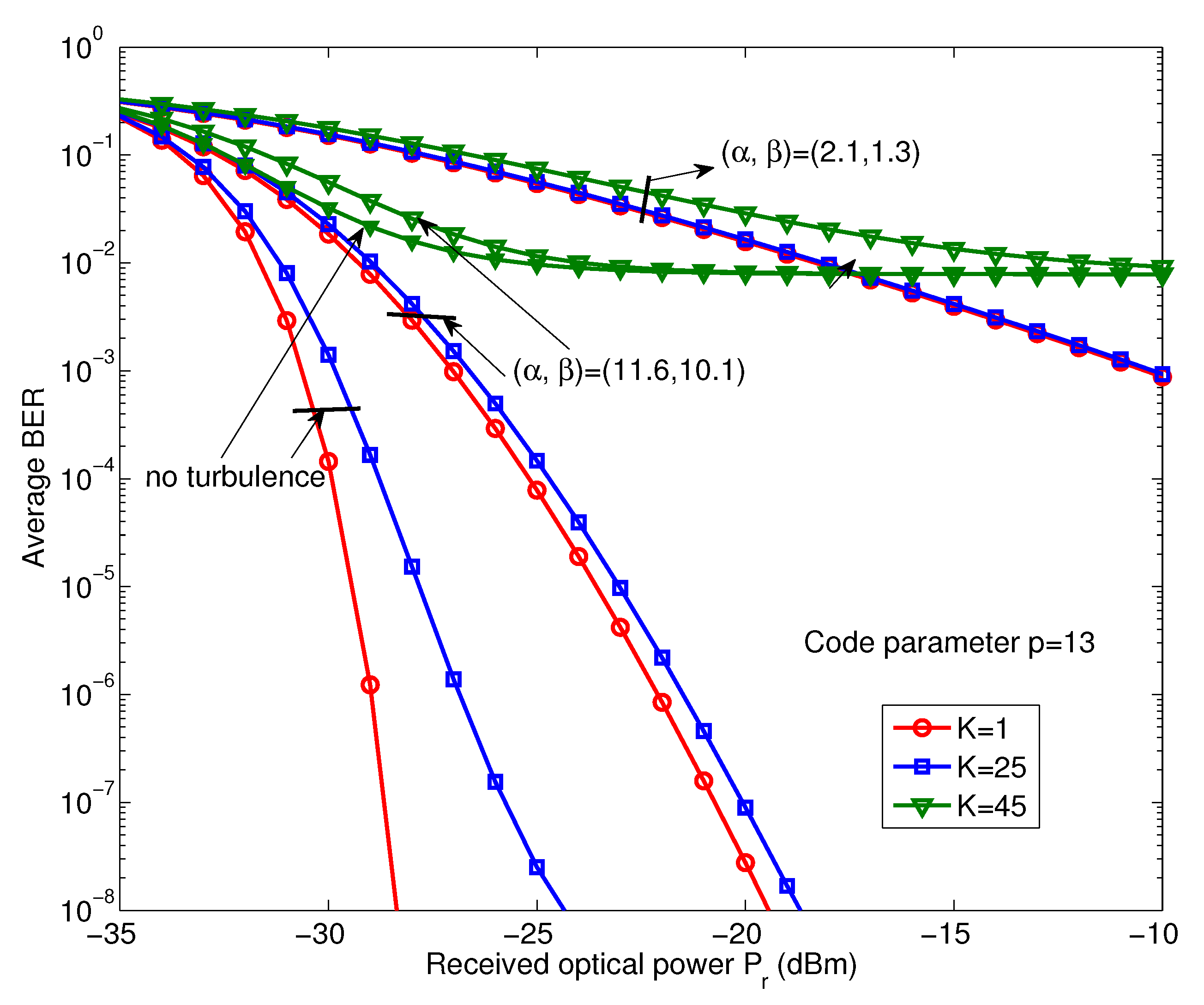
To assess the efficiency of the technique proposed in this work,
Figure 4 shows the variation of average BER performance
versus received optical power
in the turbulence channel. In this case, the number of simultaneous active users is
in the total of the interfering users when the prime number is given a fixed value
. The effect of the atmospheric turbulence on the received average BER is obvious. The transmission performance of the system deteriorates as the scintillation index increases. For example, a single active user system with average BER =
,
dBm, without turbulence outperforms the weak turbulence
=
and strong turbulence
=
by approximately 4 dBm and 20 dBm, respectively. Furthermore, three cases of the number of simultaneous active users have been considered, represented by
K= 1,
K= 25 and
K= 45 as a single user, 15% and 30% of the full-load of active users in the proposed system. As is apparent from graph, the analysis shows that the system can support 15% of the active users to provide a high transmission performance,
i.e., BER =
with received optical power
dBm in the weak turbulence. However, when the system accommodates 30% of all users, the system is unable to guarantee a reliable communication service in the whole of the turbulence strength regime. These results indicate that the system performance is highly sensitive to the atmospheric turbulence and also requires higher received optical power to overcome the BER degradation caused by MAI at the same time.
Figure 3.
Comparison of average bit error ratio (BER) performance of the PolSK and OOK schemes against normalized electric SNR in a turbulent OCDMA-FSO link.
Figure 3.
Comparison of average bit error ratio (BER) performance of the PolSK and OOK schemes against normalized electric SNR in a turbulent OCDMA-FSO link.
Figure 4.
Variation of the average BER performance versus received optical power with single user and multiple users interfering within all of the turbulence regimes.
Figure 4.
Variation of the average BER performance versus received optical power with single user and multiple users interfering within all of the turbulence regimes.
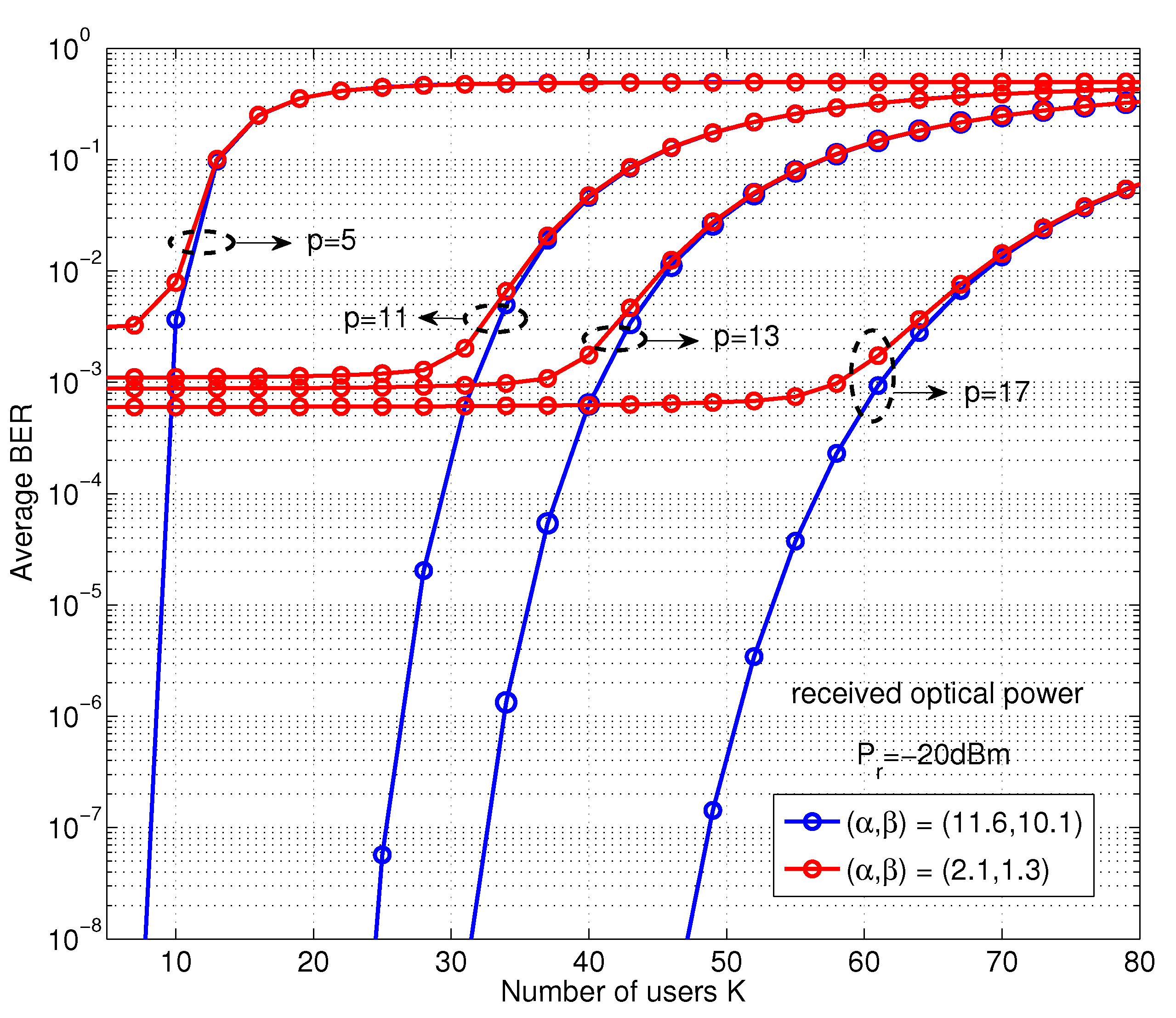
To highlight the impact of MAI on the overall system load performance, we further conduct a study on the averaged BER performance against the number of active users in the turbulence channel and the results, as shown in
Figure 5. In this analysis, for the received optical power
dBm, the system accommodates the variation number of active users, with prime number parameters (
,
,
,
) evaluated. According to the theory of the MPC property, the prime code corresponding to the code-set cardinality
is the main limiting factor of the number of supporting active users. From the graph, the BER performance improved by
p increases due to heavier code weight
p and longer code length
. In fact, the larger of the
p is closely related to the higher auto-correlation peaks or lower hit probabilities [
16]. Moreover, the BER performance gets worse as
K increases with respect to the strong mutual interference and, therefore, is unable to guarantee a reliable communication performance for larger active users, as the previous analysis in
Figure 4. In the meantime, under the different turbulence strength regimes, the impact of optical scintillation on the system BER performance is observed, especially when the signal propagates through the strong turbulent channel:
=
. These results indicate that the system employed a greater number of users, leading to growing interference. Hence, a larger prime number
p can be adopted to guarantee a reliable link performance when the system accommodates a large number of users.
Figure 5.
Variation of the average BER performance versus the number of active users K with different prime number p in both the weak and strong turbulence regimes.
Figure 5.
Variation of the average BER performance versus the number of active users K with different prime number p in both the weak and strong turbulence regimes.
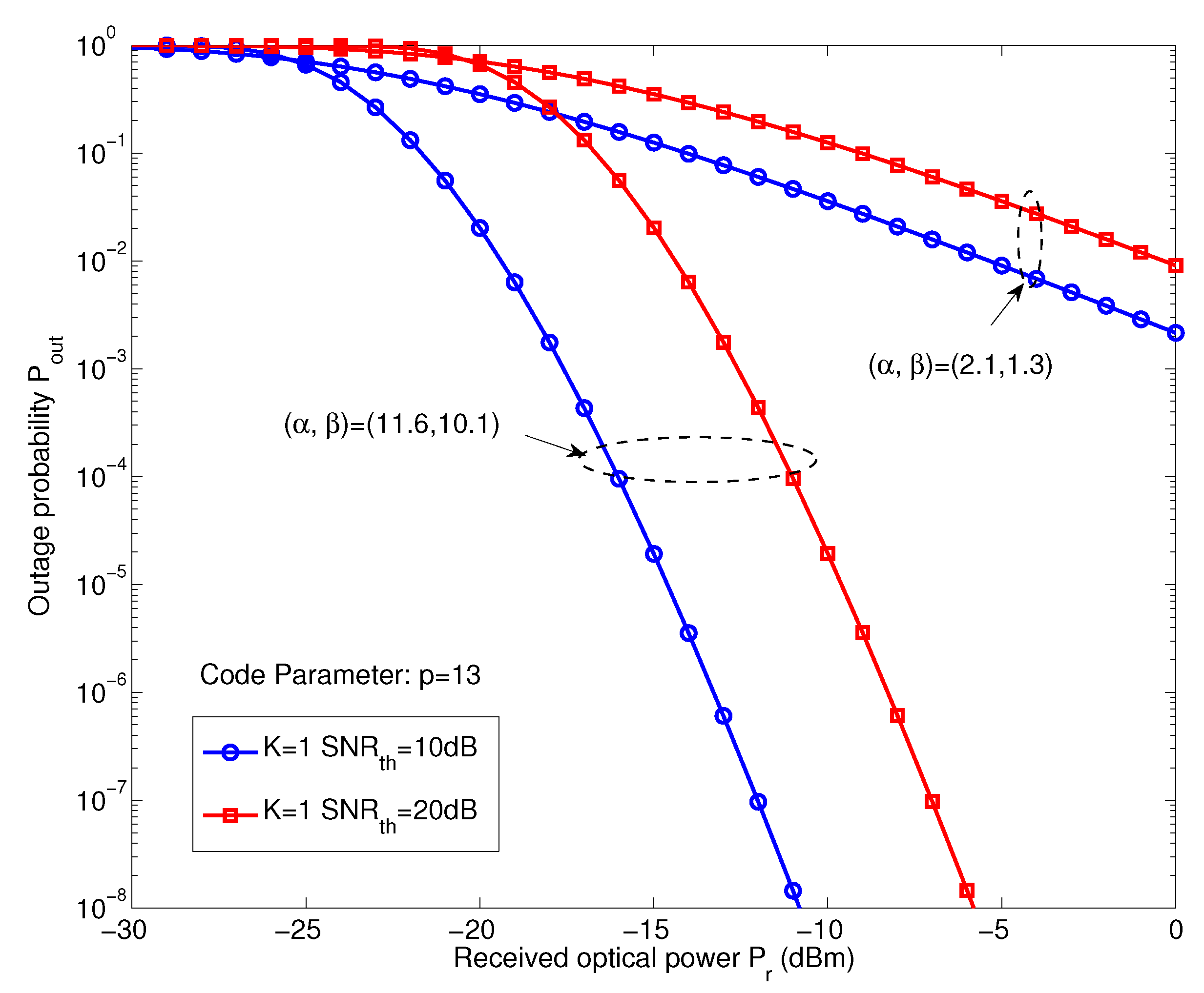
Next, we analyze the system outage probability
using Equation (26).
Figure 6 shows the variation of the outage probability
versus a single user with different SNR thresholds (
) in both the weak and strong turbulence regimes. In this analysis, the prime number is
. Two cases of the SNR threshold level have been considered,
= (10 dB, 20 dB), respectively. The system outage probability is similar to the BER performance under the turbulence fluctuation situation. From the
Figure 6, we can see clearly that the system outage probability is affected by the atmospheric turbulence and required more received optical power to achieve a better link performance. For example, when the system
is at
, the received optical power is close to
dBm in weak turbulence compared to
dBm in strong turbulence when
dB. In fact, we found that the system outage probability is also highly dependent on the effect of turbulence fluctuation. Besides, for the received optical power
dBm, the outage probability is close to
and
for
= 10 dB and
dB, respectively. Note the number of active users
in this analysis, which means that the system only suffered from the impact of turbulence fluctuation on the system performance without MAI.
Figure 6.
Variation of the outage probability versus a single user system with different values of in both the weak and strong turbulence regimes.
Figure 6.
Variation of the outage probability versus a single user system with different values of in both the weak and strong turbulence regimes.
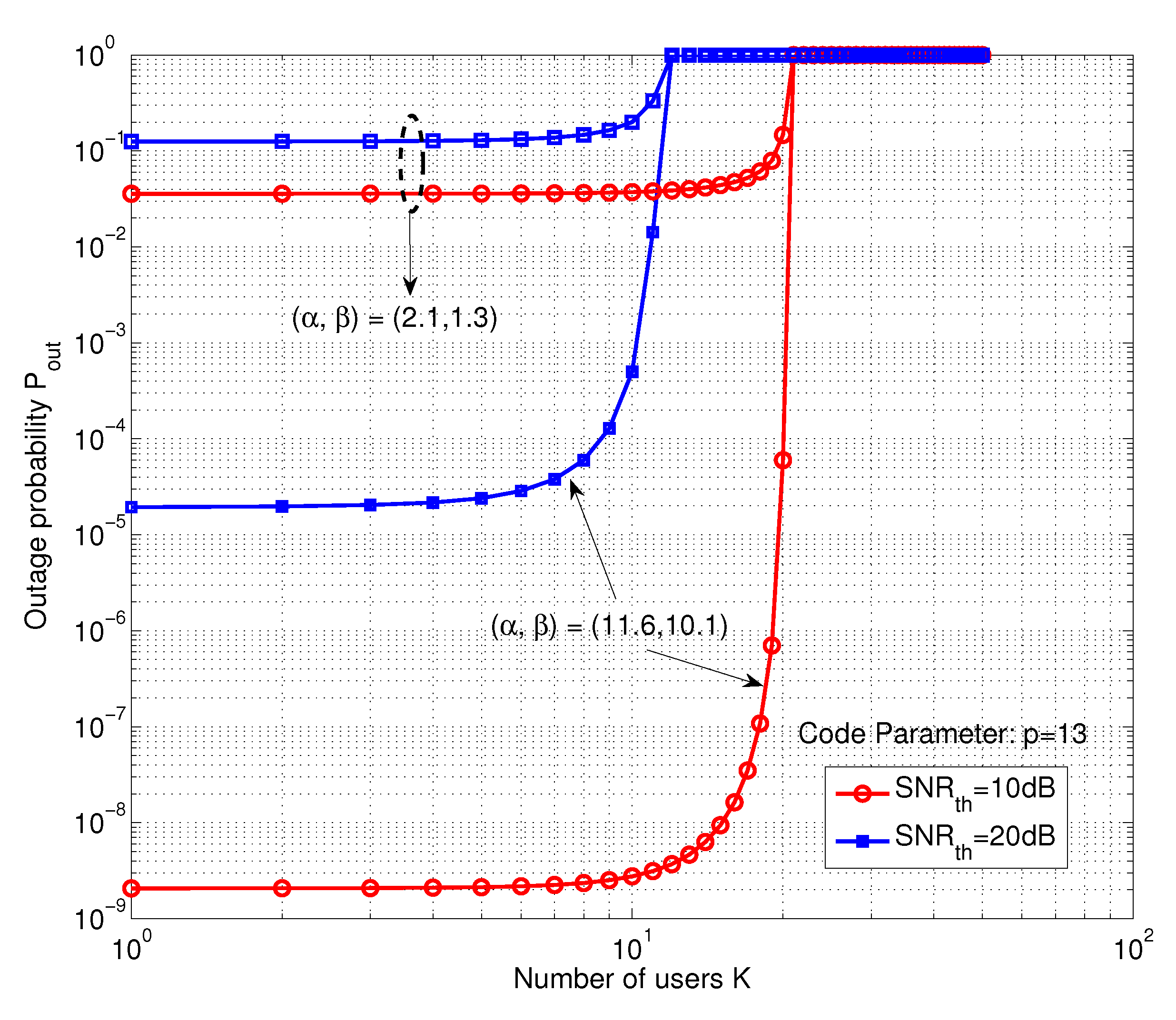
Finally,
Figure 7 shows the variation of the outage probability as a function of the number of users
K with the SNR threshold level at
= (10 dB, 20 dB), a fixed prime parameter
in both the weak and strong turbulence regimes. It can be observed that the outage probability gets worse with increasing the number of active users, due to the increase of MAI. In fact, a fixed prime number
p restricts the number of supported active users, as well as the system load performance. Because of this limitation factor, in order to tolerate the large number of active users and provide reliable communication service, a longer code is necessary. On the other hand, the graph also shows the impact of atmospheric turbulence on the outage probability performance. For the number of active users
, the outage probability increases from
to
for the weak turbulence and strong turbulence regime with the same SNR threshold,
dB.
Figure 7.
Variation of the outage probability versus the number of active users with different values of in both the weak and strong turbulence regimes.
Figure 7.
Variation of the outage probability versus the number of active users with different values of in both the weak and strong turbulence regimes.


