Article

Smart Laser Interferometer with Electrically Tunable Lenses for Flow Velocity Measurements through Disturbing Interfaces

TUD Laboratory for Measurement and Testing Techniques, TUD Faculty of Electrical and Computer Engineering, TUD School of Engineering, TU Dresden, Helmholtzstraße 18, 01069 Dresden, Germany
*
Author to whom correspondence should be addressed.
Photonics 2015, 2(1), 1-12; https://doi.org/10.3390/photonics2010001
Submission received: 6 November 2014 / Accepted: 29 December 2014 / Published: 5 January 2015

Abstract

:
Interferometric velocity measurements are of great importance at flow investigations. However, the laser beams can be distorted at the interfaces between optical media of different refractive indices. Temporal fluctuations of these distortions will cause a deterioration of the laser interferometer signals. We have harnessed the power of programmable photonics devices to eliminate this signal deterioration. Non-invasive flow velocity measurements through a rapidly fluctuating media interface with large strokes of about 100 microns are presented. Our work represents a paradigm shift for interferometric velocity measurement techniques from using static to dynamic optical elements.

1. Motivation

Laser interferometers have become a well-established and indispensable tool for precision measurements in a huge variety of scientific and industrial applications, especially in fluid mechanics. Common measurands are displacement and velocity, which are proportional to the interference signal phase and frequency, respectively. It is well known that temperature, pressure and concentration variations of the ambient air change the refractive index [1]. Typical examples in the area of fluid mechanics are temperature gradients in combustions and pressure gradients at shock waves in compressible fluids. Beside such refractive index gradients also fluctuating interfaces between two media of different optical density have to be considered. Typical examples in fluid mechanics are water channel flows with an open surface, multi-phase flows, blood flows, levitated oscillating droplets and flows alongside a phase boundary. These variations cause severe distortions of the optical wavefronts, which can result to a failure or not tolerable uncertainties of the measurements.
To overcome these challenging metrological problems the employment of adaptive optics (AO) for a smart laser interferometer is proposed. AO is predominantly known from astronomy, where it has boosted the capabilities of modern earth-bound telescopes [2,3,4,5]. In general, an AO system comprises a wavefront sensor to measure the distortion of the wavefronts, an electric control circuit and an optical modulator to correct the distortions. Wavefront distortions caused by turbulent fluctuations of the earth’s atmosphere are compensated resulting in a nearly diffraction-limited performance. A further prominent area of AO is ophthalmology. The correction of the eye aberrations enables to resolve single cells in the retina e.g., by using confocal microscopy [6] or optical coherence tomography (OCT) [7].
Also in technical metrology AO has been employed already. At optical roughness, measurements of technical surfaces the aberrations along the propagation of the laser beam have been corrected [8,9]. Also for flow measurements AO has been used [10,11,12]. First approaches have been demonstrated at laser Doppler velocimetry (LDV). AO was inserted to compensate for the random measurement deviation due to temperature gradients of heated air [10]. The LDV has been used to study gas flow stratifications.
Recently, modern AO systems have been employed for an interferometric LDV [11,12]. The deployed AO devices were supplied by Flexible Optical B.V. (OKO tech, The Netherlands) and consist of a deformable membrane mirror with integrated tip-tilt stage, a Hartmann-Shack wavefront sensor and a controller based on a PC. This adaptive LDV provide flow velocity measurements through fluctuating gas-liquid interfaces inside a water basin or channel with an open surface [11]. The distortions of the propagating laser beams due to the water surface waves have been corrected successfully, but to wave heights of only a few 10 microns [12]. At some tasks in fluid mechanics higher wave heights appear, resulting in larger amplitudes of optical distortions. In this paper we present a different approach for an adaptive, smart, interferometric LDV to overcome the former limitations. A novel electrically tunable lens and a commercially available galvanometer steering mirror are used to provide a large stroke for the wavefront correction.
For the first time, we investigate the hypothesis that electrically tunable lenses and steering mirrors enable the correction of large optical distortions in interferometry. The presented smart LDV interferometer will enable accurate flow velocity measurements through disturbing media interfaces especially at fluctuating gas-liquid interfaces. It faces large optical wavefront distortions caused by high surface waves of liquid flows, e.g., at film cooling processes, seawater salt removal, fractional distillation or processes to cool reactors.

2. Velocity Measurements through a Fluctuating Gas-Liquid Interface

2.1. Preconsiderations

The flow velocity is gathered by an interferometric LDV technique, which allows high spatial and temporal resolutions together with a low velocity measurement uncertainty. The basic principle is to intersect two coherent laser beams under a small angle, forming a Mach-Zehnder interferometer. In the volume of intersection, a system of almost parallel interference fringes develops. If a particle carried with the flow to be investigated passes through the intersection volume of the laser beams, it scatters light that is modulated in amplitude with the Doppler frequency f. The velocity component vx perpendicular to the interference fringe system orientation is resulting to
v x = f d
with the measured Doppler frequency f [13]. The a-priori calibrated interference fringe spacing d is calculated by
d = λ 2 sinθ ( 1 + z   cos 2 θ ( z   cos 2 θ - z W ) z R 2 cos 2 θ - z W ( z   cos 2 θ - z W ) )
with λ as the laser wavelength, θ as the intersection half angle of the interfering laser beams, z as the axis along the bisecting line of the two laser beams, zW as the axial shift of the beam waist position relative to the center of the measurement volume and zR as the Rayleigh length of the Gaussian laser beams, which is defined by zR = πw02/λ, where w0 is the radius of laser beam waists [13].
Considering the propagation of the laser beams through an open water surface to measure the flow velocity inside the water basin, the measurement properties of an LDV are changed by a moving air-water interface. In order to evaluate the contributions of different effects, the height function h(x,t) of the air-water interface is developed into a Taylor series. This procedure is in analogy to the representation with Zernike polynomials. For simplification, only the one-dimensional expression is considered:
h ( x , t )    =    h ( x 0 , t ) S t r o k e + ( x x 0 ) h ( x , t ) x | x = x 0 T i l t + 1 2 ( x x 0 ) 2 2 h ( x , t ) x 2 | x = x 0 C u r v a t u r e + ...
The optical distortions caused by the fluctuating air-liquid interface can deteriorate the measurement properties as follows:
  • 0th order: Height or stroke of the air-water interface. For a lift of the interface a parallel shift of the beam occurs whereas the beam direction remains constant. The consequence is a shift of the position of the measurement volume, i.e., a dislocation of the measurement position. Furthermore a signal frequency jitter is introduced, if a stochastic fluctuation of the air-water interface occurs.
  • 1st order: Tilt of the air-water interface. Due to refraction, a tilt of the interface will change the propagation direction of the laser beam. Going to the two-dimensional consideration, it has to be distinguished between a tilt in the plane spanned by the two partial beams δx and a tilt in the direction normal to this plane δy.
    (a)
    Tilt δx in x-direction (tip): On one side a displacement of the measurement position results and on the other side there is a change in the intersection half angle θ of the interfering laser beams. Due to a change of the Rayleigh length zR or the beam waist position zw a variation of interference fringe spacing d results, see Equation (2). The standard deviation σd represents these variations. Using Equation (1) and the propagation law of statistical independent measurement, uncertainties of the fringe spacing σd and the signal frequency σf the relative velocity measurement uncertainty yields to [13]
    σ v x v x = ( σ f f ) 2 + ( σ d d ) 2
    (b)
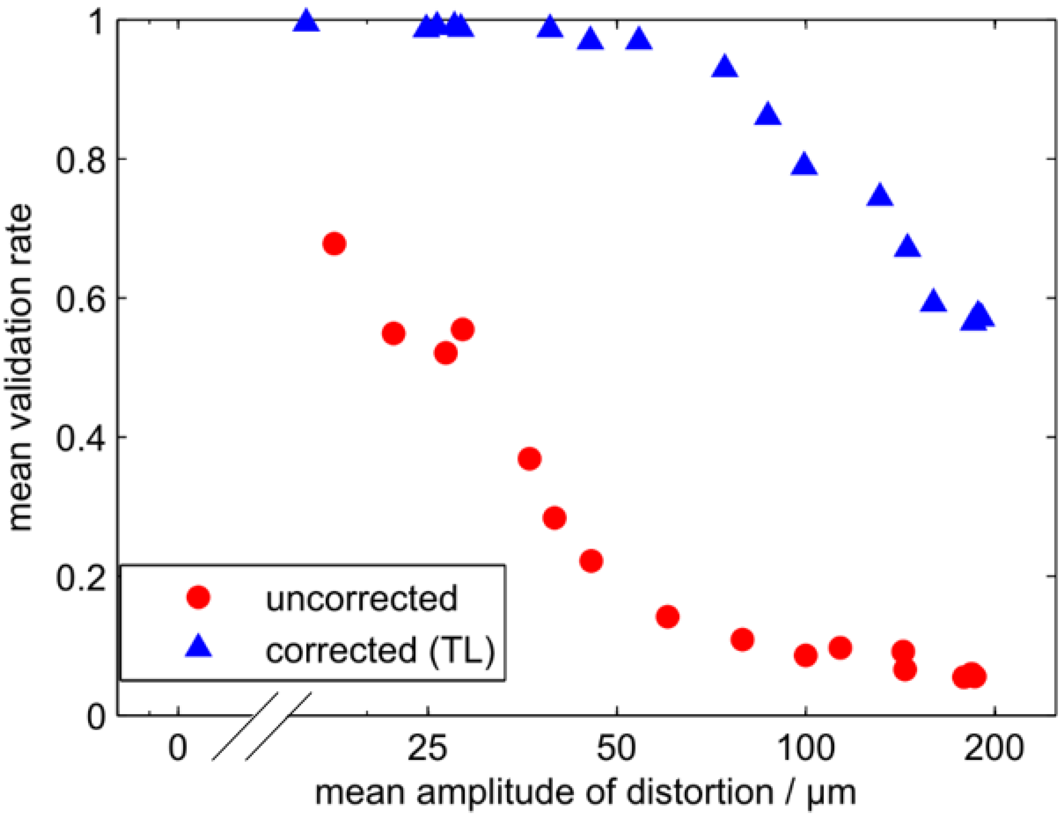
    Tilt δy in y-direction: A beam deflection in the y-direction normal to the plane spanned by the two Gaussian beams will result in skew rays. The reduced overlap of the partial laser beams results in lower interference visibility and signal-to-noise ratio (SNR). Only measurement signals with a sufficient SNR are considered for further evaluation. The corresponding validation rate is given by the ratio between the evaluable and all signals detected. It represents a crucial figure-of-merit of the LDV system, since on the one hand the maximum frequency bandwidth of the velocity fluctuations and on the other the effective measurement time is determined. In the worst case of negligible laser beam overlapping no measurements can be performed at all, represented by a validation rate of zero.
  • 2nd order: Parabolic curvature of the interface. Due to refraction, a curvature of the interface induces a lens effect on the beam propagation. It changes the radius of the beam waist w0 and the position zW of the beam waist. As a consequence, the fringe spacing d is changed according to Equation (2), which in general enhances the velocity measurement uncertainty, see Equation (4).
  • 3nd order and higher orders: Distortions of the surface with high spatial frequency. The wavefront of the laser beams will be locally distorted, leading to inhomogeneities in the interference fringes. The fringe spacing can vary in all three directions. In consequence, the measurement uncertainty will increase, see Equation (4).
It should be noted that the different distortion orders strongly depend on the incidence point of the beam with respect to the surface wave, i.e., on the phase of the wave. If the beam passes through a maximum of the water wave, a convergent lens will mainly affect the beam, if it passes through a minimum, a divergent lens effect appears. If the beam propagates through the zero-crossing of the wave, mainly a beam deflection and a phase jitter will occur.
A previous experimental analysis revealed that low-order Taylor series orders, respectively Zernike polynomials (piston/stroke, tip/tilt and defocus) dominate the wavefront distortions [12]. Distortions of higher orders, i.e., with higher spatial frequency can be neglected at the considered flow measurement task. This can be easily understood since at the water surface the diameter of the laser beams is around some millimeters and therefore significantly smaller than the typical wavelength of the observed capillary waves of 50 mm. This wavelength results by considering the highest amplitude (mode) of the measured Fourier spectrum of 6 Hz and the estimated phase velocity of the surface wave of 0.3 m/s.
These preconditions define the spatial and temporal parameters of the AO system to be implemented. In general, several optical modulators are available for the correction of wavefront distortions, e.g., deformable membrane mirrors, micro-electro-mechanic-system (MEMS) mirror arrays and liquid-crystal spatial light modulators. In our former research work [11,12] we have employed a deformable membrane mirror exhibiting 17 electrostatic actuator elements and built-in piezoelectric tip-tilt unit. An obstacle of the deformable membrane mirror was its restricted defocus range due to the limited curvature of the membrane. Considering an optical imaging magnification from the mirror to the water surface of one, only defocuses up to about 0.3 diopters can be corrected. It is not enough at large heights of the surface waves of the investigated experiment. In the next section we will present a new optical measurement system able to handle the correction of large distortions.

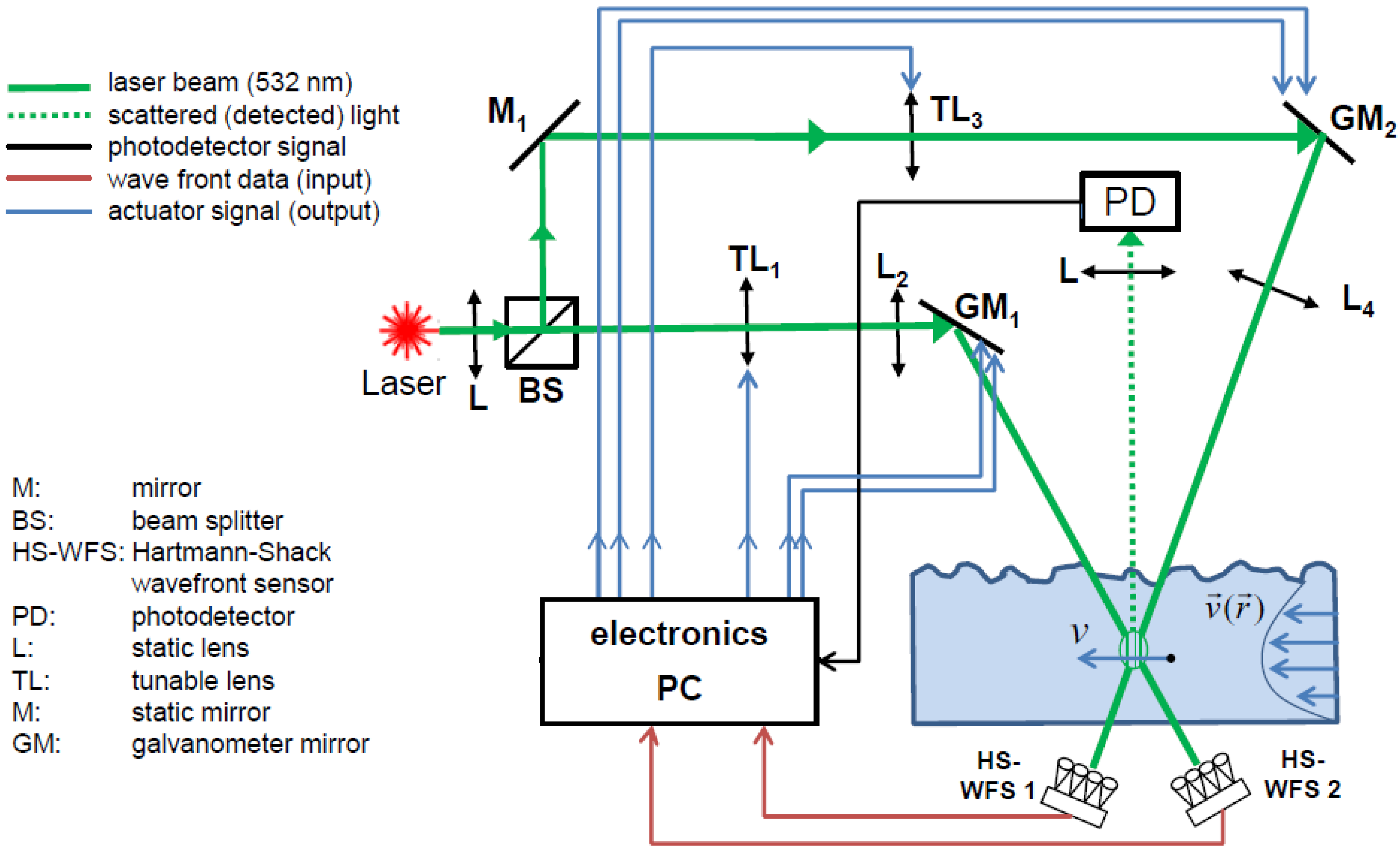
2.2. Smart Laser Interferometer with Electrically Tunable Lenses

In order to correct large wavefront distortions exhibiting a strongly limited spatial bandwidth only the first and second orders of the Taylor series are considered, see Equation (3). The approach is to employ a combination of electrically tunable lenses, used to correct the 2nd order distortion and two-axis galvanometric mirrors, used to correct the 1st order distortions. Electrically tunable lenses have been suggested and employed for several measurement tasks already [14,15,16,17]. In this paper a novel adaptive silicone membrane lens, provided by Prof. U. Wallrabe (University of Freiburg, IMTEK, Laboratory for Microactuators, Germany) is inserted. The used principle is based on optofludics [14]. A piezo-electric actuator is applied for the variation of the pressure of a fluid. It results in a change of the shape of a transparent silicon membrane. In consequence, the focal length of the lens can be steered by an electrical voltage of the piezo-electric actuator [14,17]. The employed electrically tunable membrane lens offers several advantages:
  • A high defocus range of up to ±40 diopters can be covered.
  • A 3 dB temporal bandwidth of over 60 Hz. It should be high enough to correct the distortions of the capillary waves at the current experiment.
  • Due to its outer size of 20 mm diameter the tunable lens is ideal for being integrated into compact sensors.
To correct for 1st order aberrations, i.e., tip/tilt, two biaxial two-dimensional, electromagnetically driven steering mirror (Model OIM101, Optics in Motion LLC, 4223 Rutgers Ave, Long Beach, CA 90808, USA) were used. It enables scanning over an angular range of ±1.5° (+/−26 mrad) with <2 µrad resolution and a 3 dB bandwidth of >550 Hz. Two Hartmann-Shack camera sensors (type Basler—piA640-210gm, supplied by Flexible Optical B.V., Polakweg 10–11, 2288 GG Rijswijk ZH, The Netherlands) were employed, one for each transmitted laser beam, to measure the wavefront distortions caused by the capillary waves on the free water surface. In Figure 1 the setup of the smart LDV interferometer is shown.
Based on the wavefront data of the Hartmann-Shack camera, the following actuating variables have to be computed to guarantee a complete control of the two partial beams:
  • The focal lengths of the tunable lens for the first and second partial beams
  • The deflections of the mirror in x-direction for the first and second partial beams
  • The deflections of the mirror in y-direction for the first and second partial beams
Before the adjustment control can operate a calibration has to be performed. Therefore electric signals are applied to the control system in the absence of the distortion, i.e., a silent air-water interface of the basin. The resulting changes of the wavefront are evaluated and the relationship between signals and wavefront deformation are stored as a transfer matrix. During the operation of the control loop the inverse procedure is used. The deviation of the measured wavefront from the default wavefront is calculated and multiplied with the inverse matrix to determine the electric signals which compensate the wavefront distortion. An integral controller is used as the control type, resulting in a vanishing control deviation. The control loop is realized as a twin system whose identical parts control both laser beams simultaneously. The number of performed control cycles per time unit depends on different parameters of the control loop. This control rate is mainly influenced by the number of evaluated spots of the Hartmann-Shack wavefront sensor. In the case of four evaluated spots a control rate of 1 kHz is achieved. In order to gain a sufficient sensitivity regarding the wavefront distortion, usually 20 spots are evaluated. Here the control loop operates at 540 Hz. Mainly due to the settling time of the PC-based controller, hence the latency time distortions with frequencies up to 42 Hz could be suppressed reliably. This is fast enough to cover the main components of the spectrum of the occurring capillary waves [12].
Figure 1. Smart laser Doppler velocimeter (LDV) interferometer with two implemented electrically tunable lenses (TL) and two two-axis galvanometer mirrors (GM). The smart LDV compensates the wavefront distortions caused by the fluctuating air-water interface. A twin control loop was realized to control both partial laser beams simultaneously. In the overlapping area of the two laser beams a fringe system is generated. The scattered light from tracer particles moving through this fringe system is measured by the photodetector (PD). In result the flow velocity v is determined.
Photonics 02 00001 g001

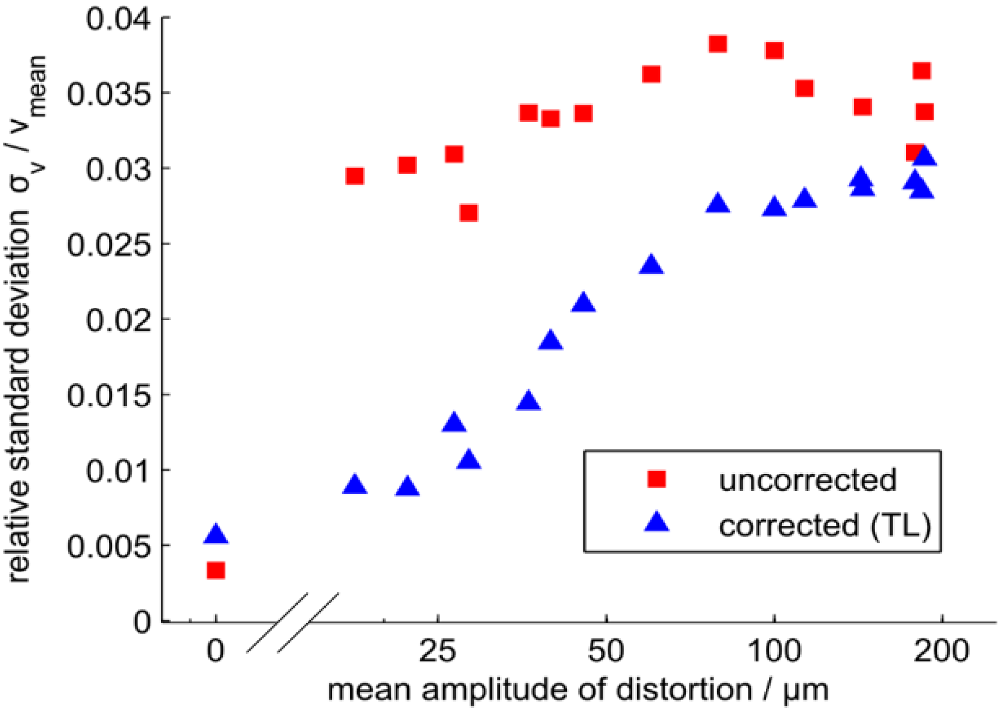
2.3. Performance of the Distortion Correction

To characterize the quality of the distortion correction of the AO system, different figures of merit can be considered. A primary quantity is the interference visibility, i.e., the modulation degree of the burst LDV signals. Moreover, the validation rate, i.e., the number of valid high SNR measurement signals with respect to the number of the total acquired signals, can be used as a figure of merit as well. Although it depends on the interference visibility and also on the SNR, this quantity is more appropriate for the flow velocity measurements. The validation rate corresponds to the measurement uncertainty and also the temporal resolution of the flow velocity.
The experiments were performed in a water basin. A water pump was used to excite capillary surface waves in the basin which acted as the optical distortion. The distortion amplitude can be varied by changing the driving voltage of the pump. In order to investigate the LDV measurement properties a moving pinhole was used as a scattering object. Below the basin an optical chopper rotated the pinhole at a constant speed v0. According to Equation (1) the measured Doppler signal frequency is given by f = v0/d. In conclusion, variations of the signal frequency are caused mainly by changes of the fringe spacing d and therefore by the optical distortions from the fluctuating air-water interface. This procedure allows us to study the improvements by the used AO system, see Figure 2 and Figure 3.
Figure 2. Mean validation rate with and without distortion correction by the tunable lens (TL) in dependence of the mean amplitude of the distortion, i.e., height of the surface water wave.
Photonics 02 00001 g002
In Figure 2 the mean validation rate is displayed in dependence of the mean amplitude of the distortion. The AO system results in a significant improvement for the validation rate. At distortion amplitudes, i.e., mean surface wave heights of 75 µm the validation rate is enhanced from 12% to 92% with the AO-based distortion correction. Also, compared to the former AO technique [11,12] a significant improvement has been achieved. The hypothesis to correct large distortion strokes by electrically tunable lenses and galvanometer mirrors has been confirmed.
As a benefit, the measurement time can be reduced or more valid signals can be gathered in a predefined measurement time. The higher data rate also increases the temporal resolution, thus making it possible to evaluate spectrally broad turbulence, which is crucial for the investigation of complex flows [18,19,20].
Figure 3. Relative standard deviation of the velocity measurement with and without distortion correction by the tunable lens (TL) as a function of the mean amplitude of the distortion.
Photonics 02 00001 g003
Figure 3 shows the mean velocity measurement uncertainty in dependence of the mean distortion amplitude. The reason for the increased velocity standard deviation is that the spacing of the fringe system changes with the crossing angle but also with the position of the beam waist of the Gaussian beams. These effects are compensated with the tilting mirrors and the adaptive lenses, respectively. It can be seen that the velocity standard deviation is reduced significantly below mean surface wave amplitudes of about 100 µm when applying the AO correction.

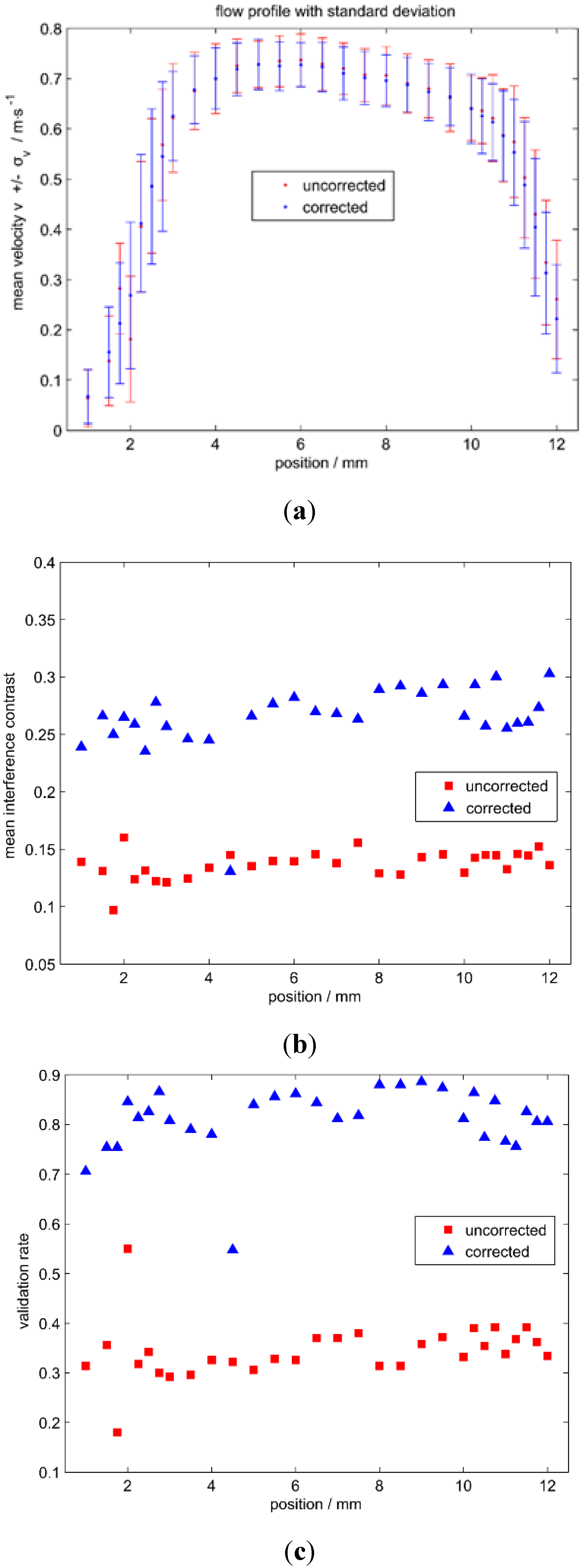
2.4. Flow Velocity Measurements

A demonstration experiment was performed to proof the functionality of the wavefront correction for a real world application. A nozzle of 10 mm diameter was submerged in the water basin to generate on the one hand the flow to be measured and on the other hand capillary waves on the water surface as the optical distortion. The technical relevance is given by film flows. Since film flows exhibit a high surface-to-volume ratio, they are characterized by a high heat and mass transport. Consequently, film flows are widespread in industrial applications especially for chemical process engineering, convection processes, cleaning, evaporation, desalination of seawater, condensation and distillation.
The measurement volume of the smart interferometric LDV was located 10 mm in front of the nozzle and the flow profile was measured by mechanically traversing the nozzle. Both laser beams pass through the fluctuating water surface and are corrected. Figure 4a shows the mean velocity profile of the nozzle. The measurement uncertainty bars represent the velocity standard deviation which is mainly dominated by the turbulence of the flow. In Figure 4b,c, the mean interference contrast and the mean validation rate are displayed, respectively. It is obvious that the interference contrast is significantly improved by the wavefront correction, which consequently leads to a higher number of valid signals, i.e., a higher validation rate. For a certain measurement time more valid signals can be collected which reduces the confidence interval. Both the reduced uncertainty, see Figure 3, and the higher number of valid signals, contribute to an improvement of the confidence interval as shown in Figure 4d.
Figure 4. Measurement of the flow profile of a submerged water nozzle by the smart LDV interferometer. The experiments have been conducted for a distortion amplitude, i.e., mean surface wave height of 50 µm. Both laser beams pass the free water surface, see Figure 1. They are controlled both by an adaptive optics (AO) system using electrically tunable lenses and galvanometer mirrors. (a) Profile of the mean velocity with the velocity standard deviation as uncertainty bars. The velocity standard deviation is dominated mainly by the flow turbulence; (b) Mean interference contrast; (c) mean validation rate and (d) confidence interval, all shown as a function of the position alongside the nozzle cross-section.
Photonics 02 00001 g004aPhotonics 02 00001 g004b

3. Conclusions

Refractive index variations, caused by fluctuating refractive index fields or interfaces, can deteriorate the properties of velocity measurements. A lower rate of valid high SNR signals and an increased velocity uncertainty can be the consequences. To overcome these limitations, the principle of wavefront correction by means of AO was applied. AO is an emerging technology with constantly improving opportunities. Standardized fabrication processes, improved techniques and new methods significantly lower barriers of their employment. In this contribution, a smart Mach-Zehnder interferometer for flow velocity measurements was presented, that was equipped with a twin AO system to corrected wavefront distortions caused by a fluctuating air-water interface. Using the wavefront correction, the interference contrast and the number of valid high SNR signals was improved significantly. Measurements in the presence of optical distortions can be performed in a shorter time and with a higher statistical reliability. AO offers new perspectives for metrology at applications that have hardly been accessible by laser measurement techniques so far. The presented velocity measurements through disturbing fluid interfaces are important at several fields of fluid mechanics. At convection research, an improved understanding of heat transfer by turbulence can be achieved, which can enhance the energy efficiency of film cooling devices. Furthermore, in biomedical research, optical blood flow measurement can improve the investigation of diseases such as aneurysm and arteriosclerosis.

Acknowledgments

The authors acknowledge financial support from the German Research Foundation (DFG, grant Cz 55/30) by a Reinhart Koselleck project. We thank M. Stürmer and U. Wallrabe (Department of Microsystems Engineering—IMTEK, Laboratory for Microactuators, University of Freiburg, Germany) for supporting us with the electrically tunable membrane lenses.

Author Contributions

All authors contributed to the writing of the manuscript. H.R. performed the experimental measurements. C.L. performed numerical simulations [12], which are the basis of the design of the presented experimental setup. J.W.C. and L.B. conceived the general research direction.

Conflicts of Interest

The authors declare no conflict of interest.

References

  1. Birch, K.P.; Downs, M.J. An Updated Edlén Equation for the Refractive Index of Air. Metrologia 1993, 30, 155–162. [Google Scholar] [CrossRef]
  2. Beckers, J.M. Adaptive Optics for Astronomy: Principles, Performance, and Applications. Ann. Rev. Astron. Astrophys. 1993, 31, 13–62. [Google Scholar] [CrossRef]
  3. Hardy, J.W. Adaptive Optics for Astronomical Telescopes; Oxford University Press: New York, NY, USA, 1998. [Google Scholar]
  4. Glindemann, A.; Hippler, S.; Berkefeld, T.; Hackenberg, W. Adaptive Optics on Large Telescopes. Exp. Astron. 2000, 10, 5–47. [Google Scholar] [CrossRef]
  5. Tyson, R. Principles of Adaptive Optics, Third Edition; CRC Press: Boca Raton, FL, USA, 2010. [Google Scholar]
  6. Roorda, A.; Romero-Borja, F.W.D., III; Queener, H.; Hebert, T.; Campbell, M. Adaptive optics scanning laser ophthalmoscopy. Opt. Express 2002, 10, 405–412. [Google Scholar] [CrossRef] [PubMed]
  7. Hermann, B.; Fernández, E.J.; Unterhuber, A.; Sattmann, H.; Fercher, A.F.; Drexler, W.; Prieto, P.M.; Artal, P. Adaptive-optics ultrahigh-resolution optical coherence tomography. Opt. Lett. 2004, 29, 2142–2144. [Google Scholar] [CrossRef] [PubMed]
  8. Fuh, Y.K.; Hsu, K.C.; Fan, J.R. Rapid in-process measurement of surface roughness using adaptive optics. Opt. Lett. 2012, 37, 848–850. [Google Scholar] [CrossRef] [PubMed]
  9. Fuh, Y.K.; Fan, J.R. Experimental investigation of a flowing fluid layer on metal surface roughness measurement and aberration correction using adaptive optics. Opt. Rev. 2013, 20, 433–437. [Google Scholar] [CrossRef]
  10. Klepikov, K.E.; Kulybin, V.M.; Rinkevichius, B.S. Using the principles of adaptive optics in laser Doppler anemometry. In Proceedings of the Vsesoiuznyi Seminar po Opticheskim Metodam Issledovaniia Potokov 1st, Novosibirsk, USSR, 23–25 May 1989. (In Russian)
  11. Büttner, L.; Leithold, C.; Czarske, J. Advancement of an Interferometric Flow Velocity Measurement Technique by Adaptive Optics. Int. J. Optomech. 2014, 8, 1–13. [Google Scholar] [CrossRef]
  12. Büttner, L.; Leithold, C.; Czarske, J. Interferometric Velocity Measurements through a fluctuating Gas-Liquid Interface Employing Adaptive Optics. Opt. Express 2013, 21, 30653–30663. [Google Scholar] [CrossRef] [PubMed]
  13. Czarske, J.; Büttner, L.; Razik, T.; Müller, H. Boundary layer velocity measurements by a laser Doppler profile sensor with micrometre spatial resolution. Measurement Sci. Technol. 2002, 13, 1979–1989. [Google Scholar] [CrossRef]
  14. Schneider, F.; Draheim, J.; Kamberger, R.; Waibel, P.; Wallrabe, U. Optical characterization of adaptive fluidic silicone-membrane lenses. Opt. Express 2009, 17, 11813–11821. [Google Scholar] [CrossRef] [PubMed]
  15. Khan, S.A.; Riza, N.A. Demonstration of a No-Moving-Parts Axial Scanning Confocal Microscope Using Liquid Crystal Optics. Opt. Commun. 2006, 265, 461–467. [Google Scholar] [CrossRef]
  16. Riza, N.A.; Sheikh, M.; Webb-Wood, G.; Kik, P.G. Demonstration of three-dimensional optical imaging using a confocal microscope based on a liquid-crystal electronic lens. Opt. Eng. J. 2008, 47, 063201:1–063201:9. [Google Scholar] [CrossRef]
  17. Koukourakis, N.; Finkeldey, M.; Stürmer, M.; Leithold, C.; Gerhardt, N.C.; Hofmann, M.R.; Wallrabe, U.; Czarske, J.W.; Fischer, A. Axial scanning in confocal microscopy employing adaptive lenses (CAL). Opt. Express 2014, 22, 6025–6039. [Google Scholar] [CrossRef] [PubMed]
  18. Fischer, A.; Schlüßler, R.; Haufe, D.; Czarske, J. Lock-in spectroscopy employing a high-speed camera and a micro-scanner for volumetric investigations of unsteady flows. Opt. Lett. 2014, 39, 5082–5085. [Google Scholar] [CrossRef] [PubMed]
  19. Fischer, A.; König, J.; Czarske, J.; Peterleithner, J.; Woisetschläger, J.; Leitgeb, T. Analysis of flow and density oscillations in a swirl-stabilized flame employing highly resolving optical measurement techniques. Exp. Fluids 2013. [Google Scholar] [CrossRef]
  20. Neumann, M.; Friedrich, C.; Kriegseis, J.; Grundmann, S.; Czarske, J. Determination of the phase-resolved body force produced by a dielectric barrier discharge plasma actuator. J. Phys. D 2013, 46, 042001. [Google Scholar] [CrossRef]

