1. Introduction
Augmented Reality (AR) integrates virtual information into the real environment, enabling real-time interaction with digital content and providing an immersive visual experience [
1,
2]. As a rapidly developing field, AR’s near-eye display systems project display pixels into the user’s eyes via optical elements to form distant virtual images [
3,
4], merging virtual and real information [
5]. Owing to its lightweight structure, large field of view (FOV) [
6], and wide eye box, diffractive waveguide has become the mainstream optical solution for consumer AR glasses. Diffractive waveguide systems [
7] working principle involves incident light being diffractively coupled into the waveguide via an input grating, propagating through total internal reflection (TIR) [
8,
9,
10,
11], and then exiting through an output grating to reach the human eye. Classified by grating type, this technology is divided into volume holographic grating waveguide (VHGW) [
12,
13,
14,
15] and surface relief grating waveguide (SRGW) [
16,
17,
18]. Given the mature manufacturing process of surface relief gratings (SRG) and their widespread application in AR glasses [
19], this study focuses on the SRGW approach.
Despite progress in the commercialization of diffractive waveguide systems, significant challenges remain in image quality, particularly image uniformity, a key factor affecting user experience [
5]. For instance, Ni et al. reported that the angular illuminance uniformity in a two-dimensional surface relief grating waveguide could be as low as 34% prior to optimization [
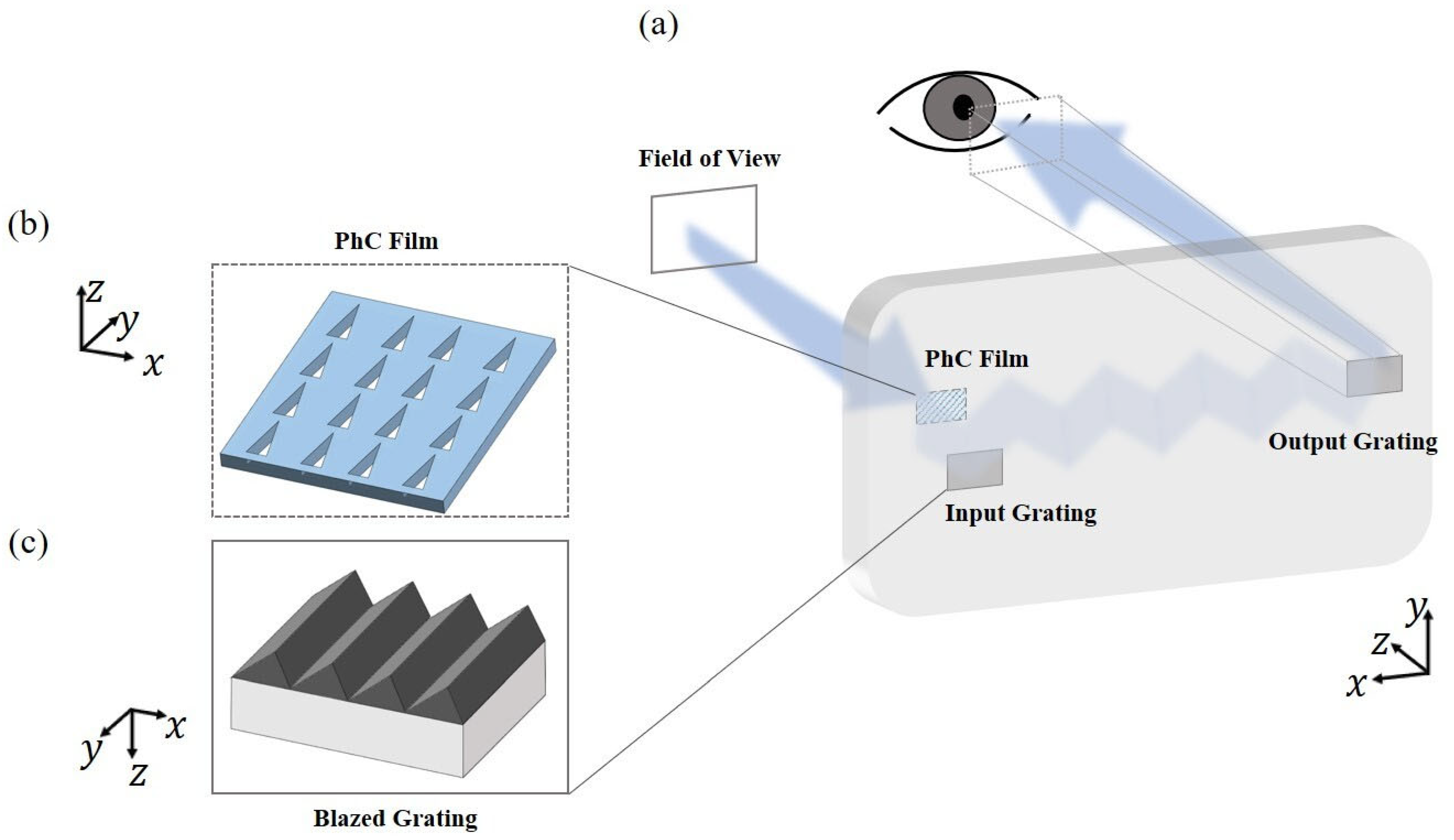
17]. This issue stems from the inherent selectivity of diffractive elements for the angle and wavelength of incident light: differences in diffraction angles across wavelengths lead to uneven total internal reflection (TIR) path lengths (e.g., red light undergoes fewer TIRs than green light, while blue light undergoes more), thereby causing brightness and color non-uniformity. For the SRGW technical scheme, this study focuses on addressing the issue of uneven output images. It first optimizes the detailed parameters of SRG and waveguides through simulations, while innovatively proposing a technical model that integrates a photonic crystal film on the input grating side (
Figure 1). The study verifies that this photonic crystal film can effectively improve the imaging uniformity of SRGW systems and confirms that the model maintains this optimization effect across different input grating types.
Figure 1 illustrates the schematic diagram of the diffraction waveguide system used in this study. The diffractive waveguide system is mainly composed of diffractive gratings and a flat glass plate. The diffraction grating is placed on one surface of the flat glass plate, serving as the input coupler to allow light to freely enter and exit the waveguide. Based on the traditional diffraction waveguide system, we added a photonic crystal film on the opposite side of the input grating. When the incident light enters the waveguide, it first passes through the photonic crystal film. The transmitted light then enters the waveguide and interacts with the diffraction grating, causing diffraction. The first-order diffracted light meets the conditions for total internal reflection within the waveguide, undergoing multiple total internal reflections until it encounters the output grating again, directing the light into the human eye. By precisely designing the parameters of the input grating, we can optimize the first-order diffraction efficiency in the waveguide to its maximum, ensuring that most of the light propagates mainly in this direction after diffraction. Additionally, the photonic crystal film further enhances the uniformity of the output image in the waveguide. This paper discusses the application of waveguide structures based on diffractive optics in AR. The current work explores how to utilize the capabilities of photonic crystal film to help address the issue of uneven brightness output in diffraction waveguide technology solutions.
2. Photonic Crystal Film Simulation and Polarization Regulation
Photonic crystals are composed of periodic microstructures with dimensions comparable to or smaller than the wavelength of light [
20]. By adjusting the properties of the periodic structure, such as the period, shape, and dielectric constant, they can control the propagation and modulation of light. Photonic crystal induces Bragg scattering [
21] in the photonic bandgap through the periodic distribution of the dielectric constant, achieving bandgap transmission for light [
22,
23]. In recent years, photonic crystals have demonstrated significant potential in various technological applications, including AR, they offer considerable advantages in expanding the user’s field of view and improving image quality.
The polarization control of photonic crystal film [
24,
25,
26,
27,
28,
29] is mainly achieved by adjusting their structural parameters. By reasonably designing and adjusting these parameters, it is possible to control the transmission or reflection of photonic crystal film for different polarization states of light [
28,
30,
31,
32]. Based on this inspiration, this study utilizes photonic crystal film to optimize the imaging uniformity of the waveguide. By designing photonic crystal with specific shapes, light propagation in certain directions can be prevented at specific frequencies or within specific wavelength ranges. According to literature, photonic crystal film with triangular hole patterns exhibits some special properties [
26,
33,
34,
35]. As shown in
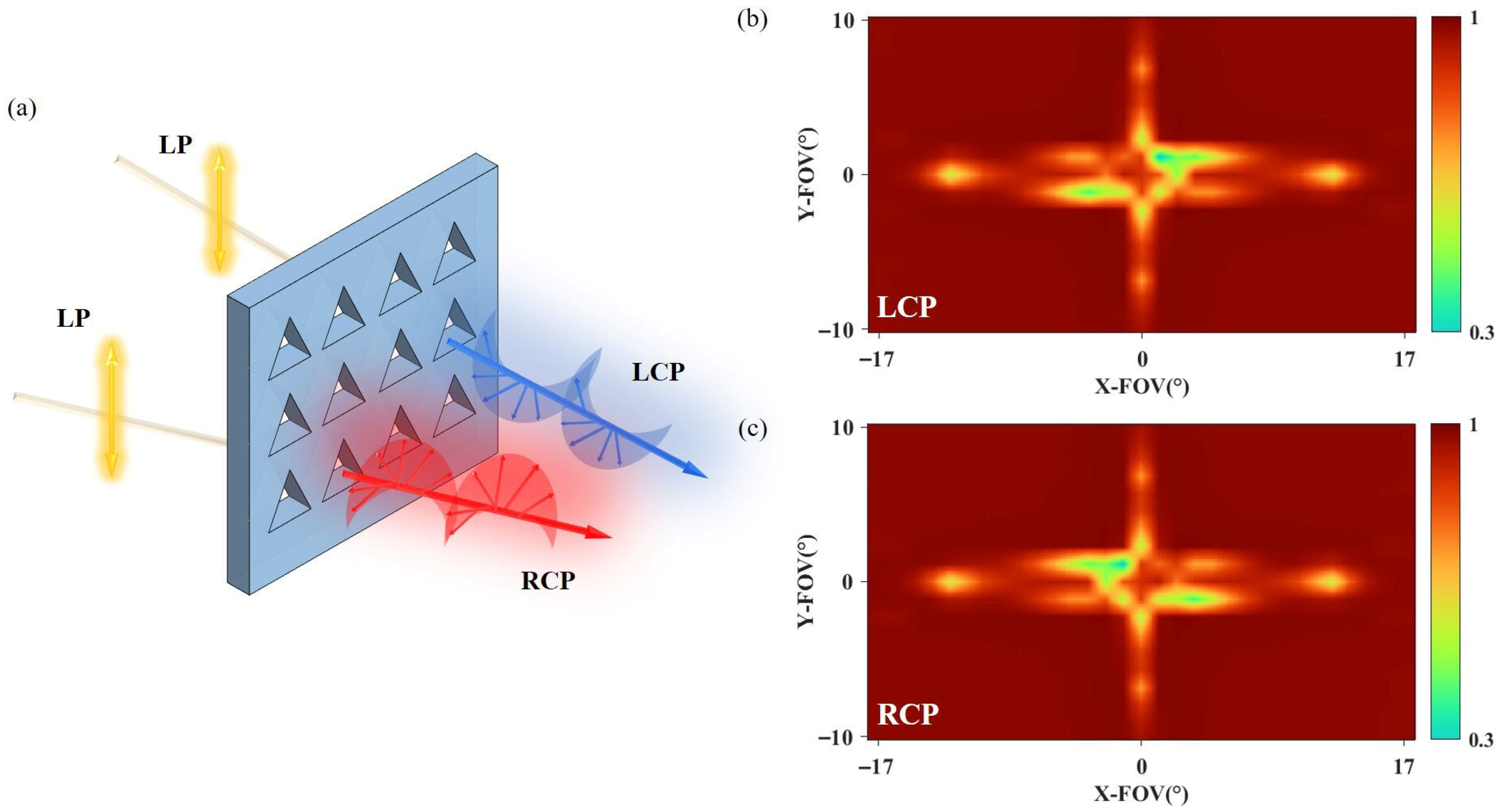
Figure 2 when left-handed or right-handed circularly polarized light is incident on such a structure, bandgaps disappear. When linearly polarized light is incident, the polarization state of the transmitted light is highly elliptical and angle-dependent.
In
Figure 2b,c, the calculations represent the transmittance of the photonic crystal film under left-handed and right-handed circular polarizations, respectively. Given the symmetric structure of the photonic crystal film, the transmittance for both left and right-handed circular polarizations is also symmetrical. It can be inferred that the polarization state of the transmitted light is correlated with the angle of incidence. Through the photonic crystal film within this structure, we can effectively regulate the transmitted light, which in turn optimizes the uniformity of the exit image in the waveguide system.
3. Comparison of Adding Photonic Crystal Film
In this study, we chose to have the incident light enter the waveguide system within the FOV region. To ensure the optimal visual effect, we selected an FOV aspect ratio of 16:9. The field of view for the incident light was set as follows: horizontal field of view (HFOV) at 20.6° and vertical field of view (VFOV) at 11.4°, with LED blue light used as the incident light source. Before establishing the waveguide system, we conducted research and design on the types of coupling gratings within the waveguide. Typically, there are various types of coupling gratings, such as tilted gratings, rectangular gratings, and blazed gratings. Our research found that the light diffracted by symmetrical rectangular gratings would not be effectively collected and transmitted to the eye, resulting in a loss of light. Therefore, in this study, we used a blazed grating as the coupling grating type in the system and performed corresponding optimization to ensure the maximum first-order diffraction efficiency in the waveguide, aiming to achieve the highest coupling efficiency of the diffracted light towards the eye.
We used Zemax OpticStudio software (Ansys Zemax OpticStudio 2023 R1.00) to simulate a diffraction waveguide system based on surface relief gratings and optimized the detailed parameters of the blazed grating. This optimization focused primarily on the base angles, period, refractive index, coating, and waveguide refractive index of the blazed grating.
During the optimization process, we first conducted a rigorous quantitative analysis and selection of the period of the blazed grating based on the physical constraints of light propagation within the waveguide. To ensure that only the first-order diffracted light could propagate via total internal reflection within the waveguide, it was necessary to suppress the total internal reflection conditions for all other diffraction orders across all incident angles. Based on the grating equation and the critical angle requirement for total internal reflection in the waveguide, theoretical calculations determined that the grating period must strictly fall within the range of d
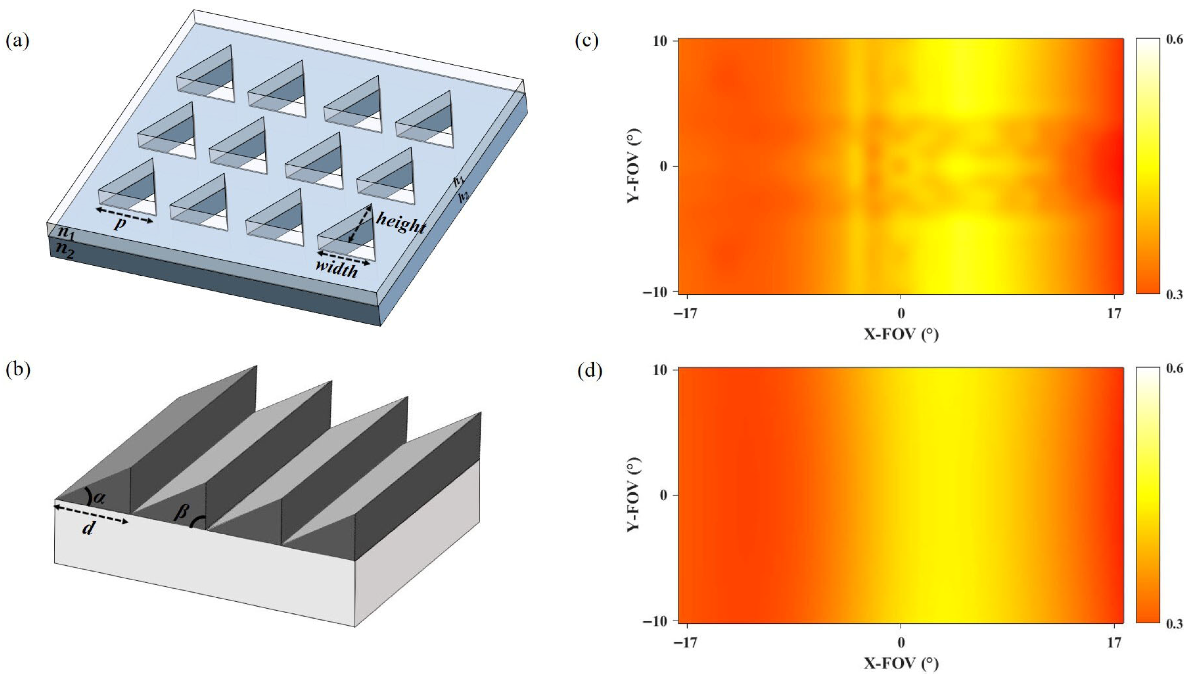
(312, 341) nm. Within this range, we further employed systematic simulations to select the period value that yielded the highest first-order diffraction efficiency and optimal uniformity performance. Subsequently, quantitative optimization was carried out on the base angles α and β of the blazed grating. Extensive simulation experiments revealed that the angle α significantly influences the output uniformity of the system. For example, when α = 62° and β = 90°, uniformity not only failed to improve but actually decreased. Therefore, a step-by-step optimization strategy was adopted: first, β was fixed while α was scanned, revealing that uniformity was optimal at α = 54°; then, based on this result, β was finely tuned, ultimately identifying a set of base angle parameters that significantly enhanced system performance. Furthermore, collaborative optimization was performed on parameters mentioned in the first paragraph, such as the refractive index, coating properties, and waveguide refractive index. These parameters were assigned optimal values based on material characteristics and simulation results, and they were co-optimized with the geometric parameters of the grating to achieve overall system performance improvement. This optimization work laid a critical foundation for the subsequent structural design and synergistic integration of the photonic crystal film. Additionally, we used Lumerical RCWA software (Ansys Optics 2023 R1) to model the photonic crystal film and performed dynamic simulations of the waveguide system with the added photonic crystal film using a combination of Zemax OpticStudio and Lumerical RCWA software. The analysis included optimization of the photonic crystal film, and the optimized structure is shown in
Figure 3.
To compare the changes in the uniformity of the output images of the waveguide system before and after the addition of photonic crystals thin film, we adopt a method of calculating variance [
36]. We embedded a detector in the waveguide model established in Zemax OpticStudio, which can collect the efficiency of first-order diffraction light in the waveguide. By analyzing and processing the data collected by the detector, we can obtain
Figure 3c,d. This shows the efficiency of first-order diffraction inside the waveguide collected over the entire FOV. By calculating the variance of the pixels in the graph, we can determine the uniformity of the output image. Through calculations, the variance of
Figure 3c before the addition of the photonic crystal film is 0.6, while the variance of
Figure 3d after the addition of the photonic crystal film decreases to approximately 0.54. Through calculation, we can infer that the uniformity of the system has improved by about 9.3% after the addition of the photonic crystal film. This configuration yielded the highest uniformity improvement observed in this study.
4. Discussion
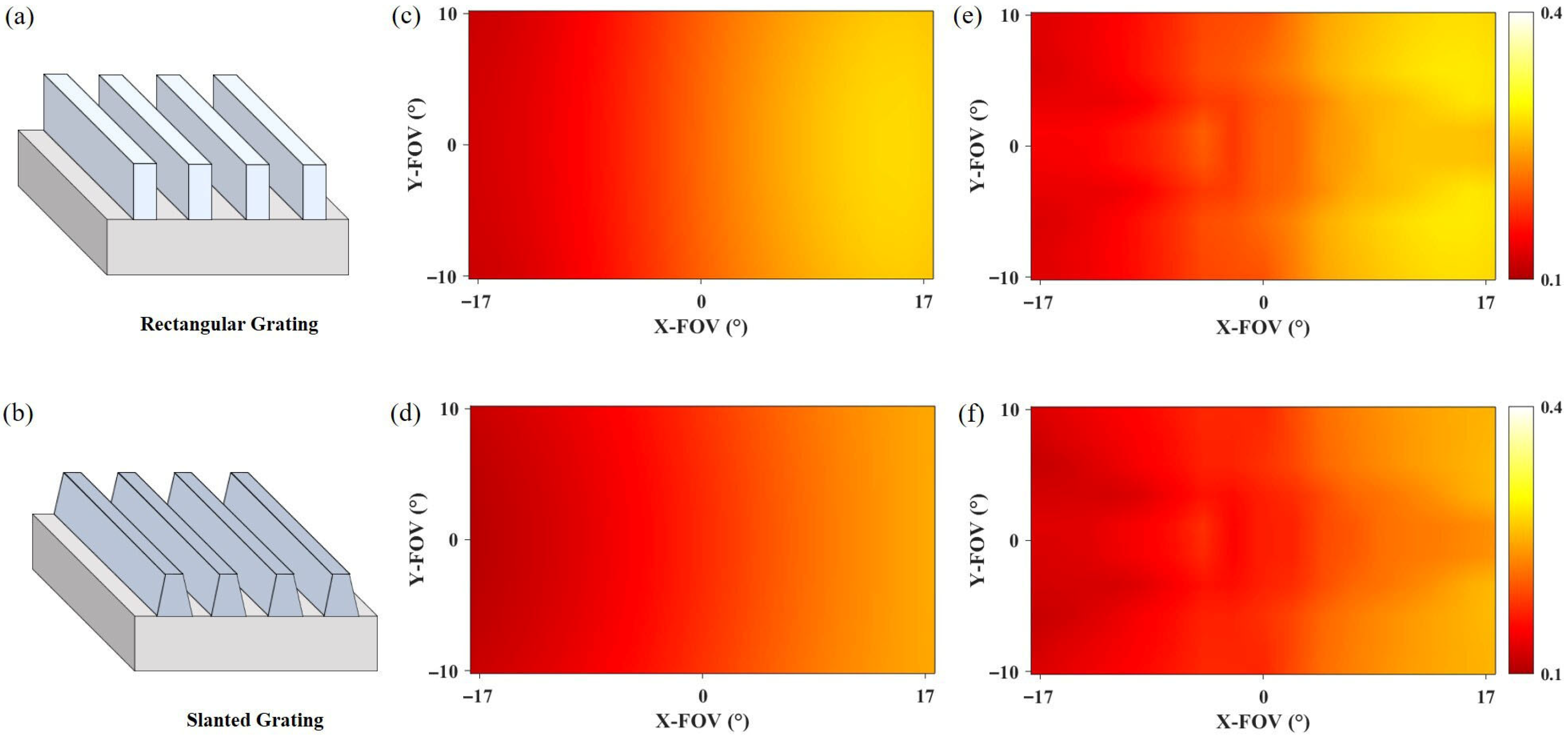
The research results of the third part indicate that introducing photonic crystal film into the waveguide can correspondingly improve the uniformity of the output images. Therefore, to verify the wide applicability of photonic crystal film, we attempted to replace the input gratings in the waveguide with rectangular gratings and tilted gratings, respectively, studying the effect of photonic crystal film on different types of input gratings. The simulation results are shown in
Figure 4. Result analysis reveals that photonic crystal film can improve the uniformity of images for both rectangular gratings and tilted gratings, increasing uniformity by 6.4% and 7.5%, respectively.
The results in
Figure 4 show that photonic crystal film can also improve the uniformity of other types of relief gratings, but the overall diffraction efficiency is generally low.
The underlying mechanism of this phenomenon stems from the fundamental differences in how various grating structures modulate the optical field. The blazed grating, due to its asymmetric sawtooth-like structure, possesses high diffraction efficiency and well-defined directionality, effectively concentrating light energy into the +1 diffraction order. When combined with the photonic crystal film, the film’s modulation of the polarization state of transmitted light further optimizes this already efficient light field distribution, leading to a significant improvement in uniformity. In contrast, the symmetric structure of the rectangular grating results in a more dispersed energy distribution among diffraction orders and a lower baseline diffraction efficiency, thus limiting the synergistic gain with the photonic crystal film. Although the slanted grating possesses a degree of asymmetry, its efficiency remains lower than that of the blazed grating, resulting in an intermediate uniformity improvement. This clearly demonstrates that the beneficial effect of the photonic crystal film is highly dependent on the input grating’s inherent ability to concentrate light energy into the desired diffraction order. Gratings with higher baseline efficiency and superior directionality exhibit more pronounced synergistic effects with the film.
5. Conclusions
In this article, we designed a specific photonic crystal film aimed at optimizing the uniformity issue in the output image of the waveguide. With the introduction of the photonic crystal film, compared to before. The uniformity of the output image is improved.
In this study, the enhancement effect of photonic crystal film on the image uniformity of diffractive waveguide system is verified by simulation, and it should be clear that the effect is limited to monochromatic scenarios: the light source used in the study is LED blue light (monochromatic light), which focuses on the optimization of uniformity in the luminance dimension, and the chromatic uniformity of the RGB panchromatic light and the multi-wavelength synergistic modulation problem have not yet been involved. Among the existing diffractive waveguide panchromatic solutions, the three-channel structure is the mainstream technical solution, i.e., the red, green and blue light is transmitted through independent optical paths to reduce the uniformity degradation caused by the cross-interference of the wavelengths, but the solution has the challenges of high complexity of the system integration and the need to accurately match the grating parameters of each channel. Combined with the modulation mechanism of photonic crystal film in this study, the potential direction of panchromatic performance optimization can be based on the three-channel structure: for the differences in the diffraction characteristics of red, green, and blue light at three different wavelengths, the wavelength-adapted multilayer photonic crystal film is designed, so that each layer of the photonic crystal film produces a targeted polarization modulation and uniformity optimization at a specific wavelength, and the brightness and chromaticity uniformity of the panchromatic waveguide can be achieved by the synergistic design of the monochromatic optimization and the channel integration. Through the synergistic design of monochromatic optimization and channel integration, a feasible path is provided for the improvement of brightness and chromaticity uniformity of panchromatic diffractive waveguides.
Additionally, we replaced the type of input grating with rectangular and tilted gratings. In both cases, the photonic crystal film further enhanced the uniformity of the image in the waveguide. Therefore, this study concludes that photonic crystal-based waveguide designs can serve as valuable tools in AR design, opening up a promising direction for developing brighter, higher-quality AR displays.
Author Contributions
Conceptualization, B.W.; Methodology, J.W. and B.W.; Software, J.H., C.T., C.H., C.L. and M.Y.; Writing—original draft, J.H.; Writing—review & editing, J.W. and B.W.; Project administration, B.W. All authors have read and agreed to the published version of the manuscript.
Funding
National Natural Science Foundation of China (12522420), China Postdoctoral Science Foundation Funded Project (2023M741024, 2024T170218).
Informed Consent Statement
Not applicable.
Data Availability Statement
Data underlying the results presented in this paper are not publicly available at this time but may be obtained from the authors upon reasonable request.
Acknowledgments
We would like to express our sincere gratitude to Jiajun Wang from Fudan University for his insightful discussions and for providing access to licensed software, which contributed significantly to this research.
Conflicts of Interest
The authors declare no conflicts of interest.
References
- Stein, C. Virtual Reality Design: How Upcoming Head-Mounted Displays Change Design Paradigms of Virtual Reality Worlds’. MediaTropes 2016, 6, 52–85. [Google Scholar]
- Sutherland, I.E. The Ultimate Display. Proc. IFIP Congr 1965, 2, 506–508. [Google Scholar]
- Van Krevelen, D.W.F.; Poelman, R. A Survey of Augmented Reality Technologies, Applications and Limitations. Int. J. Virtual Real. 2010, 9, 1–20. [Google Scholar] [CrossRef]
- Zhan, T.; Yin, K.; Xiong, J.; He, Z.; Wu, S.-T. Augmented Reality and Virtual Reality Displays: Perspectives and Challenges. iScience 2020, 23, 101397. [Google Scholar] [CrossRef] [PubMed]
- Kress, B.C.; Chatterjee, I. Waveguide Combiners for Mixed Reality Headsets: A Nanophotonics Design Perspective. Nanophotonics 2020, 10, 41–74. [Google Scholar] [CrossRef]
- Povinelli, M.L.; Johnson, S.G.; Joannopoulos, J.D.; Pendry, J.B. Toward Photonic-Crystal Metamaterials: Creating Magnetic Emitters in Photonic Crystals. Appl. Phys. Lett. 2003, 82, 1069–1071. [Google Scholar] [CrossRef]
- Han, J.; Liu, J.; Yao, X.; Wang, Y. Portable Waveguide Display System with a Large Field of View by Integrating Freeform Elements and Volume Holograms. Opt. Express 2015, 23, 3534–3549. [Google Scholar] [CrossRef]
- Cheng, D.; Wang, Y.; Xu, C.; Song, W.; Jin, G. Design of an Ultra-Thin near-Eye Display with Geometrical Waveguide and Freeform Optics. Opt. Express 2014, 22, 20705–20719. [Google Scholar] [CrossRef] [PubMed]
- Liu, Z.; Wang, D.; Gao, H.; Li, M.; Zhou, H.; Zhang, C. Metasurface-Enabled Augmented Reality Display: A Review. Adv. Photonics 2023, 5, 034001. [Google Scholar] [CrossRef]
- Zhang, Z.; Zhang, Y.; Hong, B.; Wang, G. Optical Waveguide in Curved and Welded Perovskite Nanowires. Sci. China Technol. Sci. 2023, 66, 1471–1479. [Google Scholar] [CrossRef]
- Li, Y.; Huang, X.; Liu, S.; Liang, H.; Ling, Y.; Su, Y. Metasurfaces for Near-Eye Display Applications. Opto-Electron. Sci. 2023, 2, 230025. [Google Scholar] [CrossRef]
- Shi, R.; Liu, J.; Zhao, H.; Wu, Z.; Liu, Y.; Hu, Y.; Chen, Y.; Xie, J.; Wang, Y. Chromatic Dispersion Correction in Planar Waveguide Using One-Layer Volume Holograms Based on Three-Step Exposure. Appl. Opt. 2012, 51, 4703–4708. [Google Scholar] [CrossRef] [PubMed]
- Guo, J.; Tu, Y.; Yang, L.; Wang, L.; Wang, B. Holographic Waveguide Display with a Combined-Grating in-Coupler. Appl. Opt. 2016, 55, 9293–9298. [Google Scholar] [CrossRef] [PubMed]
- Gu, Y.; Weng, Y.; Wei, R.; Shen, Z.; Wang, C.; Zhang, L.; Zhang, Y. Holographic Waveguide Display with Large Field of View and High Light Efficiency Based on Polarized Volume Holographic Grating. IEEE Photonics J. 2021, 14, 7003707. [Google Scholar] [CrossRef]
- Yu, C.; Peng, Y.; Zhao, Q.; Li, H.; Liu, X. Highly Efficient Waveguide Display with Space-Variant Volume Holographic Gratings. Appl. Opt. 2017, 56, 9390–9397. [Google Scholar] [CrossRef]
- Hugonnot, E.; Delville, J.-P. Kinetics of Surface Relief Gratings Tailored by Laser-Induced Photochemical Deposition. Appl. Phys. Lett. 2002, 80, 1523–1525. [Google Scholar] [CrossRef]
- Ni, D.; Cheng, D.; Liu, Y.; Wang, X.; Yao, C.; Yang, T.; Chi, C.; Wang, Y. Uniformity Improvement of Two-Dimensional Surface Relief Grating Waveguide Display Using Particle Swarm Optimization. Opt. Express 2022, 30, 24523–24543. [Google Scholar] [CrossRef]
- Dai, G.; Yang, H.; Yin, L.; Ren, K.; Liu, J.; Zhang, X.; Zhang, J. Compact Pupil-Expansion AR-HUD Based on Surface-Relief Grating. Opt. Express 2024, 32, 6917–6928. [Google Scholar] [CrossRef]
- Mateev, G.; Nedelchev, L.; Nikolova, L.; Ivanov, B.; Strijkova, V.; Stoykova, E.; Choi, K.; Park, J.; Nazarova, D. Two-Dimensional Polarization Holographic Gratings in Azopolymer Thin Films: Polarization Properties in the Presence or Absence of Surface Relief. Photonics 2023, 10, 728. [Google Scholar] [CrossRef]
- Jin, J.; Yin, X.; Ni, L.; Soljačić, M.; Zhen, B.; Peng, C. Topologically Enabled Ultrahigh-Q Guided Resonances Robust to out-of-Plane Scattering. Nature 2019, 574, 501–504. [Google Scholar] [CrossRef]
- Wang, P.; Fan, H.; Zhang, Y.; Yao, Y.; Zhang, B.; Qin, W.; Poon, T.-C. Isotropic Two-Dimensional Differentiation Based on Dual Dynamic Volume Holograms. Photonics 2023, 10, 828. [Google Scholar] [CrossRef]
- Busch, K.; John, S. Photonic Band Gap Formation in Certain Self-Organizing Systems. Phys. Rev. E 1998, 58, 3896. [Google Scholar] [CrossRef]
- Schneider, G.J.; Hanna, S.; Davis, J.L.; Watson, G.H. Defect Modes in Coaxial Photonic Crystals. J. Appl. Phys. 2001, 90, 2642–2649. [Google Scholar] [CrossRef]
- Huang, C.; Zhang, C.; Xiao, S.; Wang, Y.; Fan, Y.; Liu, Y.; Zhang, N.; Qu, G.; Ji, H.; Han, J. Ultrafast Control of Vortex Microlasers. Science 2020, 367, 1018–1021. [Google Scholar] [CrossRef]
- Wang, B.; Liu, W.; Zhao, M.; Wang, J.; Zhang, Y.; Chen, A.; Guan, F.; Liu, X.; Shi, L.; Zi, J. Generating Optical Vortex Beams by Momentum-Space Polarization Vortices Centred at Bound States in the Continuum. Nat. Photonics 2020, 14, 623–628. [Google Scholar] [CrossRef]
- Yin, X.; Jin, J.; Soljačić, M.; Peng, C.; Zhen, B. Observation of Topologically Enabled Unidirectional Guided Resonances. Nature 2020, 580, 467–471. [Google Scholar] [CrossRef] [PubMed]
- Lee, J.; Zhen, B.; Chua, S.-L.; Qiu, W.; Joannopoulos, J.D.; Soljačić, M.; Shapira, O. Observation and Differentiation of Unique High-Q Optical Resonances near Zero Wave Vector in Macroscopic Photonic Crystal Slabs. Phys. Rev. Lett. 2012, 109, 067401. [Google Scholar] [CrossRef] [PubMed]
- Hsu, C.W.; Zhen, B.; Lee, J.; Chua, S.-L.; Johnson, S.G.; Joannopoulos, J.D.; Soljačić, M. Observation of Trapped Light within the Radiation Continuum. Nature 2013, 499, 188–191. [Google Scholar] [CrossRef]
- Yang, Y.; Peng, C.; Liang, Y.; Li, Z.; Noda, S. Analytical Perspective for Bound States in the Continuum in Photonic Crystal Slabs. Phys. Rev. Lett. 2014, 113, 037401. [Google Scholar] [CrossRef]
- Zhen, B.; Hsu, C.W.; Lu, L.; Stone, A.D.; Soljačić, M. Topological Nature of Optical Bound States in the Continuum. Phys. Rev. Lett. 2014, 113, 257401. [Google Scholar] [CrossRef]
- Zhang, Y.; Chen, A.; Liu, W.; Hsu, C.W.; Wang, B.; Guan, F.; Liu, X.; Shi, L.; Lu, L.; Zi, J. Observation of Polarization Vortices in Momentum Space. Phys. Rev. Lett. 2018, 120, 186103. [Google Scholar] [CrossRef]
- Doeleman, H.M.; Monticone, F.; Den Hollander, W.; Alù, A.; Koenderink, A.F. Experimental Observation of a Polarization Vortex at an Optical Bound State in the Continuum. Nat. Photonics 2018, 12, 397–401. [Google Scholar] [CrossRef]
- Liu, W.; Wang, B.; Zhang, Y.; Wang, J.; Zhao, M.; Guan, F.; Liu, X.; Shi, L.; Zi, J. Circularly Polarized States Spawning from Bound States in the Continuum. Phys. Rev. Lett. 2019, 123, 116104. [Google Scholar] [CrossRef] [PubMed]
- Han, C.; He, J.; Tong, C.; Liu, C.; Yang, M.; Wang, B. Generating First-Order Optical Vortex Beams by Photonic Crystal Slabs. Opt. Express 2024, 32, 27591–27598. [Google Scholar] [CrossRef] [PubMed]
- Chen, Y.; Deng, H.; Sha, X.; Chen, W.; Wang, R.; Chen, Y.; Wu, D.; Chu, J.; Kivshar, Y.S.; Xiao, S.; et al. Observation of Intrinsic Chiral Bound States in the Continuum. Nature 2023, 613, 474–478. [Google Scholar] [CrossRef] [PubMed]
- EMVA 1288; Standard for Characterization of Image Sensors and Cameras. Release 4.0 General. European Machine Vision Association: Barcelona, Spain, 2021.
| Disclaimer/Publisher’s Note: The statements, opinions and data contained in all publications are solely those of the individual author(s) and contributor(s) and not of MDPI and/or the editor(s). MDPI and/or the editor(s) disclaim responsibility for any injury to people or property resulting from any ideas, methods, instructions or products referred to in the content. |
© 2025 by the authors. Licensee MDPI, Basel, Switzerland. This article is an open access article distributed under the terms and conditions of the Creative Commons Attribution (CC BY) license (https://creativecommons.org/licenses/by/4.0/).


