Article

A Ring-Core Anti-Resonant Photonic Crystal Fiber Supporting 90 Orbital Angular Momentum Modes

1
Intelligence and Information Engineering College, Tangshan University, Tangshan 063000, China
2
Department of Information Engineering, Hebei Institute of Environmental Engineering, Qinghuangdao 066102, China
3
Institute of Modern Optics, Nankai University, Tianjin Key Laboratory of Micro-Scale Optical Information Science and Technology, Tianjin 300350, China
*
Author to whom correspondence should be addressed.
Photonics 2025, 12(9), 906; https://doi.org/10.3390/photonics12090906
Submission received: 19 June 2025 / Revised: 11 August 2025 / Accepted: 13 August 2025 / Published: 10 September 2025
(This article belongs to the Special Issue Optical Fiber Communication: Challenges and Opportunities)

Abstract

To address the issues of limited orbital angular momentum (OAM) mode count, poor transmission quality, and complex cladding structures in ring-core photonic crystal fibers, a novel OAM-supporting ring-core anti-resonant photonic crystal fiber is designed. This fiber features a high-index-doped ring-core surrounded by a three-layer anti-resonant nested tube cladding. Numerical simulations based on the finite element method indicate that the designed fiber has the ability to reliably transmit up to 90 OAM modes within the wavelength range of 1530–1620 nm. Additionally, this fiber demonstrates outstanding performance characteristics, achieving a peak effective refractive index difference of 0.0041 while maintaining remarkably low confinement loss between 10−12 dB/m and 10−8 dB/m. The minimum effective mode field area is 101.41 μm2, and the maximum nonlinear coefficient is 1.05 W−1·km−1. The dispersion is flat, with a minimum dispersion variation of merely 0.5394 ps/(nm·km). The mode purity is greater than 98.5%, and the numerical aperture ranges from 0.0689 to 0.089. The designed OAM-supporting ring-core anti-resonant photonic crystal fiber has broad application prospects in long-haul optical communication and high-speed data transmission.

1. Introduction

In recent years, with the widespread use of emerging media such as short videos, traditional optical fiber communication technologies like time-division multiplexing and polarization multiplexing can no longer meet the growing demands for higher capacity and speed. To solve this problem, researchers have proposed space-division multiplexing (SDM) technology [1]. SDM includes multi-core multiplexing [2] and mode multiplexing [3,4]. Orbital angular momentum (OAM) modes, featuring a helical phase-front, possess theoretically limitless orthogonal states defined by integer topological charges. This unique feature holds the promise of markedly enhancing both communication bandwidth and spectral utilization. Therefore, OAM mode multiplexing is considered the most promising multiplexing technique [5,6,7,8]. Although traditional communication fibers can transmit some OAM modes, their excessive losses result in short transmission distances and low information transmission accuracy. Therefore, it is necessary to find a more suitable transmission medium.
In 2012, Yue et al. proposed a ring-core photonic crystal fiber (PCF) [9]. Although this fiber supported only two OAM modes, it was the first demonstration of ring-core PCFs with the ability to transmit OAM modes. Moreover, due to structural congruence with OAM mode field distribution, ring-core photonic crystal fibers have been extensively researched for OAM modes transmission. Early studies primarily focused on enhancing OAM mode count and quality through geometric optimization of cladding air-hole shapes and arrangements. In 2016, Tian et al. demonstrated a ring-core PCF with four layers of cladding air holes, which is capable of transmitting 26 OAM modes in the wavelength range of 1.25 to 1.9 μm by the finite element method (FEM) [10]. Two years later, Bai et al. changed the cladding air holes to rectangular air holes to enhance the air-filling fraction, and supported 46 OAM modes within an 800 nm bandwidth [11]. In 2020, Hong et al. further changed the arrangement of cladding air holes to achieve 101 OAM modes [12]. Afterwards, researchers explored increasing the number and quality of OAM modes by adding ring-cores. In 2020, Wang et al. designed a novel low-crosstalk dual-ring-core PCF [13]. By inserting three layers of cladding air holes into the inter-core region to separate the guided-mode regions, it achieved support for 80 OAM modes across the 1530–1565 nm wavelength range, with isolation parameters maintained above 40 dB. In 2021, Zhao et al. changed the cladding air holes of dual-ring-core PCF to hybrid circular–rectangular structures, boosting the number of OAM modes to 80 over the 1000–1600 nm optical spectrum, with isolation parameters greater than 67 dB [14]. Building on these works, in 2022, Yang et al. also conceived a dual-ring-core PCF with BAK1 glass constituting the ring-cores [15]. The fiber demonstrated impressive capacity, propagating 232 OAM modes, of which the inner-core supported 170 modes and the outer-core supported 62 modes. However, the cladding structure of this fiber contained four layers of circular air holes, which was relatively complex and difficult to produce. In addition to structural optimizations, researchers also doped high-refractive-index materials into the ring-core to form a refractive index gradient with the surrounding low-refractive-index regions, thereby changing the propagation mode of light and enabling the waveguide to transmit a greater number of orbital angular momentum modes. As reported by Zhang et al. in their 2018 work, doping amethyst into silica to form a high-index light-guiding ring-core enabled the capacity of OAM modes to reach 110 across the combined C-L transmission band [16]. In 2020, Israk et al. introduced a novel doped high-refractive-index ring-core PCF featuring a three-layer spiral cladding design [17]. By doping SF2 into the guided mode region of the ring-core, 56 OAM modes could be stably transmitted within a super-wide bandwidth range of 1900 nm, with confinement loss spanning from 10−11 dB/m to 10−8 dB/m. In 2025, Wang et al. doped GeO2 in the light-guiding region to form a high-index ring-core and designed stratified air holes with heterogeneous geometries in the cladding to transmit 114 OAM modes [18]. Among the three aforementioned methods for increasing the number and quality of orbital angular momentum modes, doping high-refractive-index materials into the light-guiding ring-core region to form a refractive index gradient versus the neighboring low-refractive-index regions makes it easier to obtain high-quality and reliable transmission of additional orbital angular momentum states. However, the currently reported OAM-supporting ring-core photonic crystal fibers doped with high-refractive-index materials suffer from complex cladding structures and high confinement loss, making them difficult to fabricate and necessitating further improvement.
As a new type of optical fiber composed of stacked negative curvature tubes, anti-resonant photonic crystal fibers enhance optical confinement within the core through Fresnel reflection of the negative curvature tubes, further reducing the confinement loss. The fabrication of anti-resonant photonic crystal fibers is also simpler compared with other photonic crystal fibers, and their fewer structural parameters make them easier to optimize for superior performance [19,20,21]. Based on the above advantages, researchers have attempted to design high-refractive-index-doped ring-core anti-resonant photonic crystal fibers to solve the aforementioned problems of complex cladding structures and high confinement losses in high-refractive-index-doped ring-core PCFs. Published in 2022, Mehedi et al. designed a OAM-supporting ring-core anti-resonant photonic crystal fiber [22]. By introducing anti-resonant units in the cladding, this OAM-supporting fiber’s fabrication difficulty was greatly simplified, but it could only support 64 OAM modes and still needed further improvement.
To simplify the manufacturing complexity of OAM-supporting photonic crystal fibers and achieve superior transmission of more OAM modes, this paper designs a novel OAM-supporting ring-core anti-resonant photonic crystal fiber. The fiber features an elevated-index ring-core surrounded by a three-layer nested tube cladding. This structure enhances the core-cladding refractive index contrast, enabling support for more OAM modes. The finite element numerical analysis demonstrates that the fiber exhibits outstanding capabilities, supporting the reliable propagation of 90 OAM modes over the 1530–1620 nm range (C + L band). The maximum difference in effective refractive index stands at 0.0041, while confinement loss ranges from 10−12 dB/m to 10−8 dB/m, a minimum effective mode area of 101.41 μm2, a maximum nonlinear coefficient of 1.05 W−1·km−1, flat dispersion with a minimum dispersion variation as low as 0.5394 ps/(nm·km), mode purity greater than 98.5%, and a numerical aperture in the range of 0.0689 to 0.089.

2. Principle and Proposed Structure of PCF

In circularly symmetric optical fiber waveguides, OAM modes are composed of four vector eigenmodes. The formula for synthesizing OAM modes from the four vector eigenmodes is expressed as [17]:
OAM ± l , m ± = HE l + 1 , m e v e n ± i HE l + 1 , m o d d OAM ± l , m = EH l 1 , m e v e n ± i EH l 1 , m o d d l > 1 OAM ± l , m ± = HE 2 , m e v e n ± i HE 2 , m o d d OAM ± l , m = TM 0 , m ± i TE 0 , m l = 1
where the subscripts “l” and “m” denote the topological charge and the radial order of OAM modes, respectively. HEeven refers to the even mode components of the HE eigenmodes, while HEodd represents their odd mode components. Similarly, EHeven refers to the even modes of the EH eigenmodes, while EHeven represents their odd mode components. The helical-wavefront orbital angular momentum modes are synthesized from the even modes and odd modes of HE or EH, requiring a phase difference of π/2 between them during synthesis. In the Formula (1), the symbol “i” denotes this π/2 phase difference. The subscript symbol “±” serves to indicate the rotational direction (right/left) of wavefronts in OAM modes, while the superscript symbol “±” is used to denote the handedness (right/left) of circular polarization. When l = 1, the TM and TE modes exhibit a considerable disparity in their propagation constants, resulting in mode walk-off as they travel. This walk-off causes the OAM mode to transmit erratically through the optical fiber. Consequently, only two OAM modes are possible for l = 1, contrasting with the four when l > 1. To prevent the degradation of OAM modes and to optimize orbital angular momentum multiplexing, lowest-order radial mode is generally favored. Moreover, for successful propagation of OAM modes through optical fibers, it is crucial that the effective refractive index differences of adjacent eigenmodes and between the HEl+1,m and EHl−1,m eigenmodes both remain above 0.0001.
The proposed OAM-supporting ring-core anti-resonant photonic crystal fiber structure is presented in Figure 1. The center is an air hole with a radius of R0 = 14 μm. When conducting FEM simulation analysis, the air’s refractive index is defined as 1. Adjacent to the central hollow core is the inner layer of the fiber, which consists of an amethyst glass tube with a thickness of d0 = 1.7 μm serving as the high-index-doped ring-core. During FEM simulation, the amethyst glass’s refractive index is set to 1.5375. Surrounding the ring-core is a middle layer composed of a silica (SiO2) glass tube, with a thickness of d1 = 1.2 μm and having a refractive index of 1.4440. Following the SiO2 tube is the outer layer of the fiber, which is very different from other OAM-supporting ring-core photonic crystal fibers. The outer layer of this fiber is an anti-resonant inner cladding with a radius of R1 = 45 μm, uniformly distributed with six groups of SiO2 embedded tubes. Each group of embedded tubes contains three negative curvature tubes, each with distinct dimensions. The outermost layer is a semicircular tube featuring an inner radius of 15 μm. Nestled within it lies a circular tube with an 11 μm inner radius, followed by an inner circular tube with a 9 μm radius. Each of these embedded tubes maintains a uniform wall thickness of 0.5 μm. In addition, this article also designed a SiO2 outer cladding for structural support, with a radius of R = 62.5 μm. The outermost layer in Figure 1 is a 5 μm-thick perfect matching layer (PML).

3. Performance and Results Analysis

The propagation quality of OAM modes in ring-core anti-resonant photonic crystal fibers is affected by the performance of the optical fibers. There are several key performance parameters. Ideal performance parameters can improve communication quality. This article analyzes the key performance parameters over 1530–1620 nm, namely in the C + L band.

3.1. Effective Refractive Index Difference (Δneff)

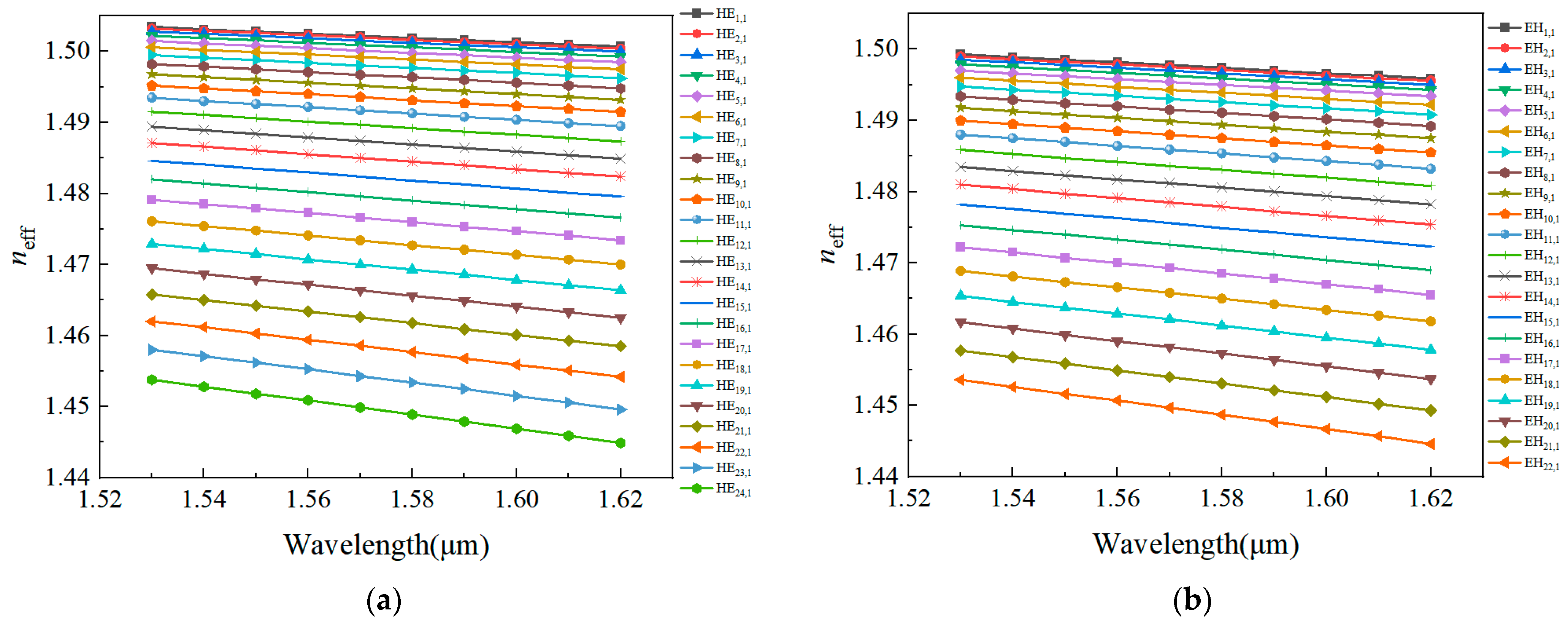
To effectively and stably transmit OAM modes in ring-core anti-resonant photonic crystal fibers, effective refractive index difference ( n e f f = n e f f H E l + 1 , m n e f f E H l 1 , m ) is the primary parameter. It is necessary for the Δneff to be above 0.0001, otherwise the hybrid eigenmodes will degenerate into linearly polarized (LP) modes. This article first presents the wavelength dependence of effective refractive index (neff) for each eigenmode, as shown in Figure 2. Figure 2a displays the results for 1st-order to 24th-order HE modes, and Figure 2b displays the results for 1st-order to 22nd-order EH modes. It is clear that for both HE modes and EH modes, the higher-order modes show a more significant variation as the wavelength changes, especially when compared to lower-order modes. The observed trend stems from the broadening of the optical field in higher-order modes with increasing wavelength, which increases the likelihood of energy leakage into the anti-resonant cladding. Consequently, the neff for these higher-order modes experiences a more noticeable decline over the same wavelength interval. Furthermore, among HE and EH modes that produce identical-order OAM modes, the HE modes consistently maintain a higher effective refractive index. Figure 3 delineates the wavelength dependence of Δneff for HE and EH eigenmodes. It is worth noting that the three-layer nested structure augments the cladding’s air-filling fraction, which significantly amplifies the difference of the refractive index between the ring-core and its adjacent regions. Thus, the Δneff of OAM modes from the 2nd to 23rd order exceeds 1 × 10⁻⁴, with a peak difference of 0.0041. The large Δneff significantly strengthens the distinction of degenerate modes and prevents intermodal coupling, enabling the designed optical fiber to support stable transmission of up to 23rd-order OAM mode. That is to say, the designed fiber provides 90 OAM modes across the 1530–1620 nm spectrum (C + L band), a key wavelength range for long-haul optical communications.
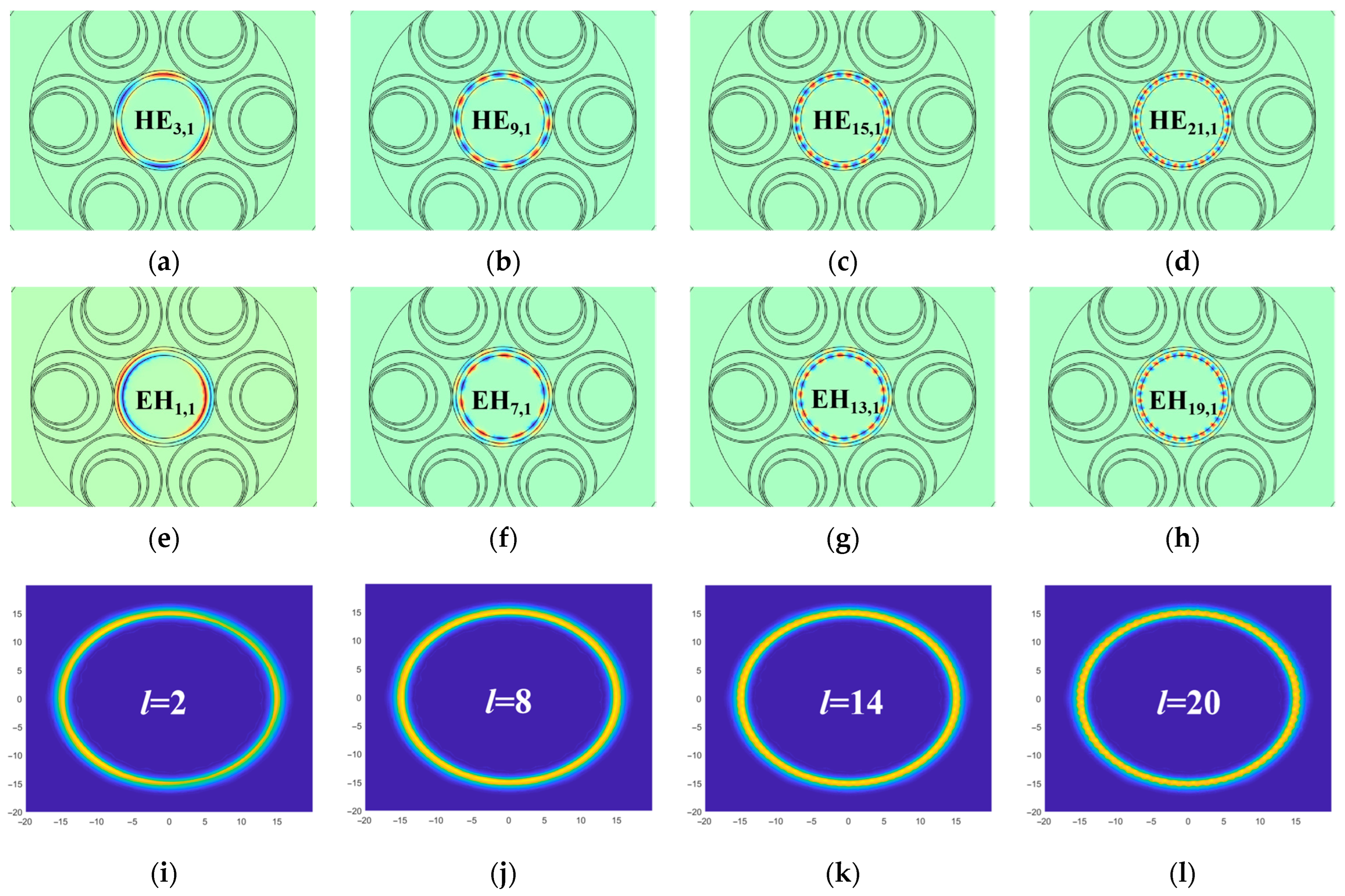
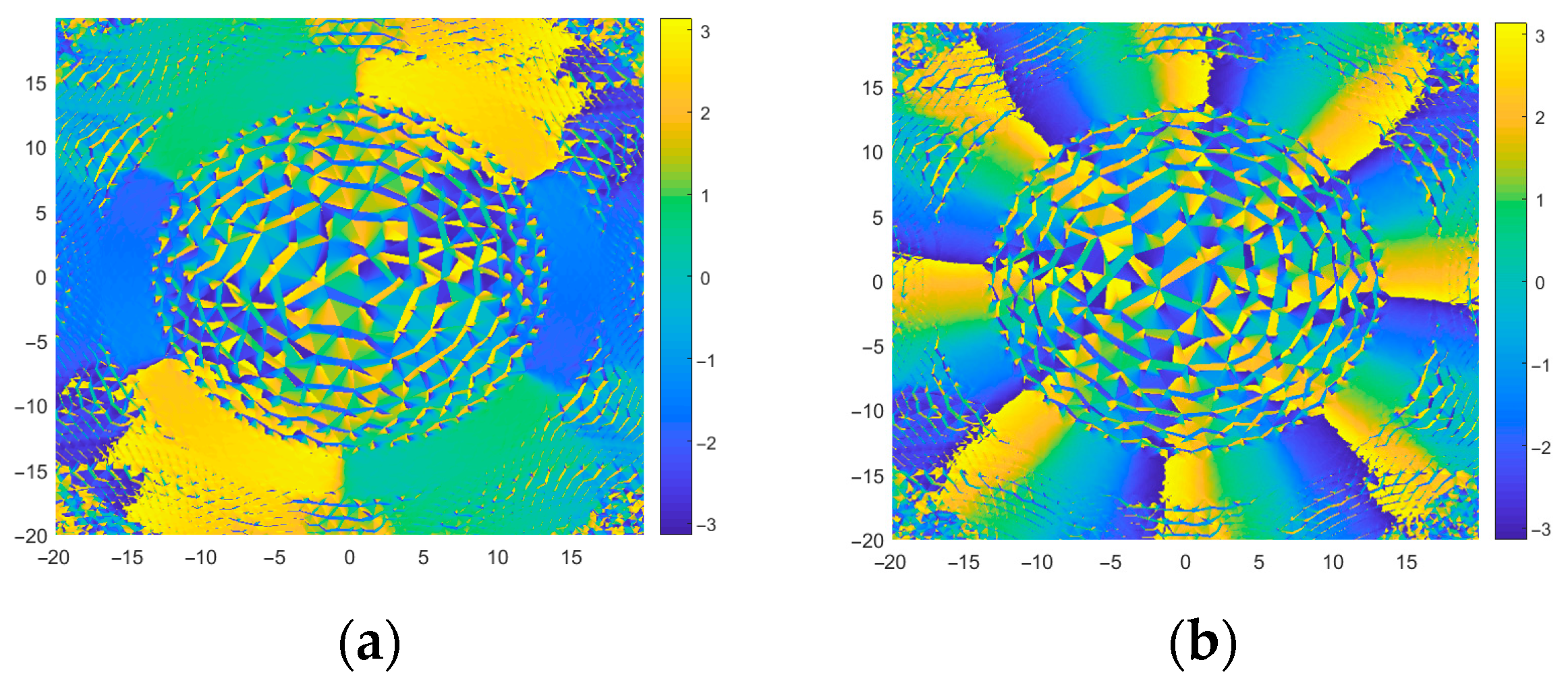
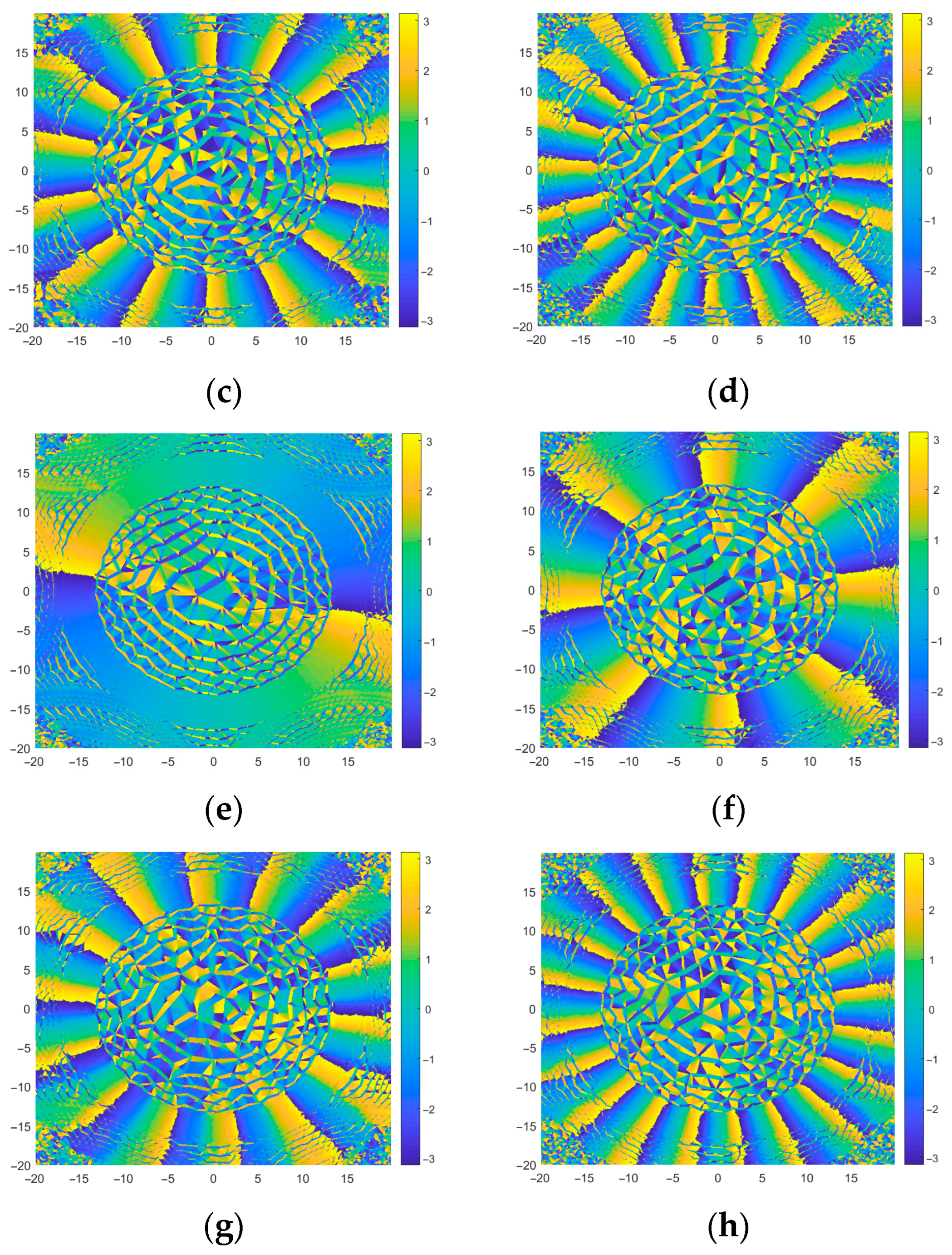
Figure 4a–h show the electric fields along the z-direction for four groups of HE even-mode components and four groups of EH even-mode components at a wavelength of 1.55 µm. As shown, electric fields of HE modes concentrate near the cladding, while those of EH modes exhibit stronger fields near the center of the air, demonstrating this method with an ability to differentiate between them. Figure 4i–l present the normalized electric field diagrams of four groups of OAM modes obtained by superimposing hybrid modes. A quick glance at the illustrations makes it clear that the intensity of the OAM’s optical field is predominantly concentrated within the ring-core, creating a distinctive circular pattern. The phase distributions of the above-mentioned four groups of OAM modes are shown in Figure 5a–h. Due to the presence of the phase factor eilθ, four groups of OAM modes exhibit a periodic phase progression of 2Ɩπ and manifest right rotation (Figure 5a–d), where the transition from blue to yellow follows a clockwise direction) and left rotation (Figure 5e–h), where the transition from blue to yellow follows a counterclockwise direction).

3.2. Confinement Loss (CL)

When optical signals propagate through an optical fiber, energy loss occurs. Confinement loss characterizes the loss of optical energy in the fiber and is a key parameter for the reliable long-distance transmission of optical signals. The fiber’s confinement loss can be calculated [10] as follows:
CL ( dB / m ) = 2 π λ μ m 20 ln 10 Im ( n e f f ) × 10 6
where Im(neff) on the formula’s right-hand side denotes the imaginary part of neff. Once neff for each eigenmode is derived through finite element analysis, substituting its absolute imaginary part into the equation allows for the confinement loss calculation.
The fluctuations of the confinement losses of the designed fiber across the C + L band are presented in Figure 6. Specifically, Figure 6a depicts the confinement loss curves for the 1st- to 24th-order HE modes, while Figure 6b shows the corresponding curves for the 1st- to 22nd-order EH modes. As observed from the figures, due to the influence of materials, waveguide structure, and mode field distribution, CLs of both HE and EH modes fluctuate in the C + L band and are maintained within a low range of 10−12 to 10−8 dB/m. This characteristic is highly conducive to transmit OAM modes over longer distances with higher reliability. Simulation results also demonstrate that CL of the HE mode reaches its minimum value of 5.16 × 10⁻¹² dB/m at 1.62 µm, while that of the EH mode achieves its minimum of 8.63 × 10⁻¹² dB/m at 1.60 µm. Such lower confinement loss is because the doped ring-core of the designed OAM-supporting PCF is tangent to the surrounding anti-resonant tube rings at critical points, resulting in minimal contact area and consequently reducing material absorption loss. Moreover, the cladding’s high air-filling fraction strengthens total internal reflection at the boundary where the doped ring-core meets the cladding, which also effectively suppresses confinement loss.
Additionally, using the finite element method, the number of OAM modes supported by the optical fiber within the bending radius range of 30–100 mm is simulated to be 90. Taking eight hybrid modes (OAM2,1, OAM8,1, OAM14,1, OAM20,1) as observation targets, the influence of bending radius variations within 30–100 mm on bending loss is analyzed. As shown in Figure 7, as the bending radius gradually increases, the bending loss can be maintained within the range of 10−12 dB/m to 10−8 dB/m, indicating that this structure possesses good bend resistance.

3.3. Effective Mode Field Area (Aeff) and Nonlinear Coefficient (γ)

To reliably transmit optical signals and achieve high-performance optical signals, the fiber should exhibit strong optical confinement capabilities and minimize influences on the optical signals. Among various performance parameters, Aeff indicates how well the optical energy is contained in the fiber, while γ measures how significantly the refractive index varies in response to changes in optical power. Aeff is inversely proportional to γ. When evaluating fiber performance, a larger Aeff is desirable, while a smaller γ is preferable. The formulas used to determine these two performance parameters are as follows [13]:
A e f f = c r o s s - s e c t i o n E ( x , y ) 2 d x d y 2 c r o s s - s e c t i o n E ( x , y ) 4 d x d y γ = 2 π n λ A e f f
Here, the term “cross-section” in the first equation denotes the fiber’s cross-section. E(x, y) in the double integral represents the distribution of the electric field over the fiber’s cross-section. The variable n in the second equation stands for the material’s optical nonlinear refractive index. As indicated by the formula, the nonlinear coefficient γ increases with n. Moreover, n is an intrinsic material property determined by the material’s electronic structure and polarization mechanisms. In this paper, amethyst glass is employed with a nonlinear refractive index of 2.6 × 10⁻²⁰ m2·W−1, which aligns closely with that of the SiO2 background material. The variable λ in the second equation is the wavelength and the range of λ in this article is 1530–1620 nm.
Figure 8a,b illustrate the variation of Aeff with λ. Over the wavelength range of 1530 nm to 1620 nm, Aeff of both HE and EH modes increases steadily as λ increases. This is because the confinement of photon energy by the ring-core weakens with increasing wavelength, making it easier for light beams to leak into the cladding. At any given wavelength, since HE modes are closer to the cladding, photon energy leaks more easily, leading to a larger Aeff for HE hybrid mode than the EH hybrid mode. Overall, Aeff of the designed ring-core anti-resonant PCF is generally distributed between 101.41 µm2 and 161.18 µm2 in the 1.53–1.62 µm band, with the minimum value occurring for the HE1,1 mode at 1.53 µm and the maximum value for the HE23,1 mode at 1.62 µm. Figure 9 shows the curve of the nonlinear coefficient of the ring-core anti-resonant PCF with wavelength in the 1.53–1.62 µm band. It is worth noting that as the nonlinear coefficient varies inversely with the Aeff, it tends to shrink as the wavelength lengthens, presenting a contrast to the trend observed in the effective mode field area. To add, HE modes have a larger Aeff than EH modes, so the former have smaller γ values. Corresponding to the results of Aeff values, the HE23,1 mode achieves the lowest γ (0.63 W−1·km−1) at 1.62 µm. Crucially, the values of γ for all hybrid modes remain consistently below 1.05 W−1·km−1 across the band, indicating that the OAM-supporting ring-core anti-resonant PCF designed in this work can stably transmit all modes and enable long-distance optical fiber communication.

3.4. Dispersion Properties (D)

Dispersion includes waveguide dispersion and material dispersion, with the former primarily shaping optical fiber performance. Waveguide dispersion, dependent on the fiber structure and material properties, manifests as a spectral broadening phenomenon where discrepancies in propagation times of incident light components with different wavelengths result in pulse spreading at the output end. When characterizing fiber transmission performance, a dispersion profile with smaller magnitude and flatter characteristics indicates superior transmission properties. The formula for calculating dispersion is given by [17]:
D = λ c d 2 Re ( n e f f ) d λ 2
where the second derivative term Re(neff) represents the real part of neff. Each eigenmode corresponds to a unique neff value. These neff values are obtained through finite element analysis. Once neff is acquired, substituting its real part into the equation allows for the calculation of dispersion.
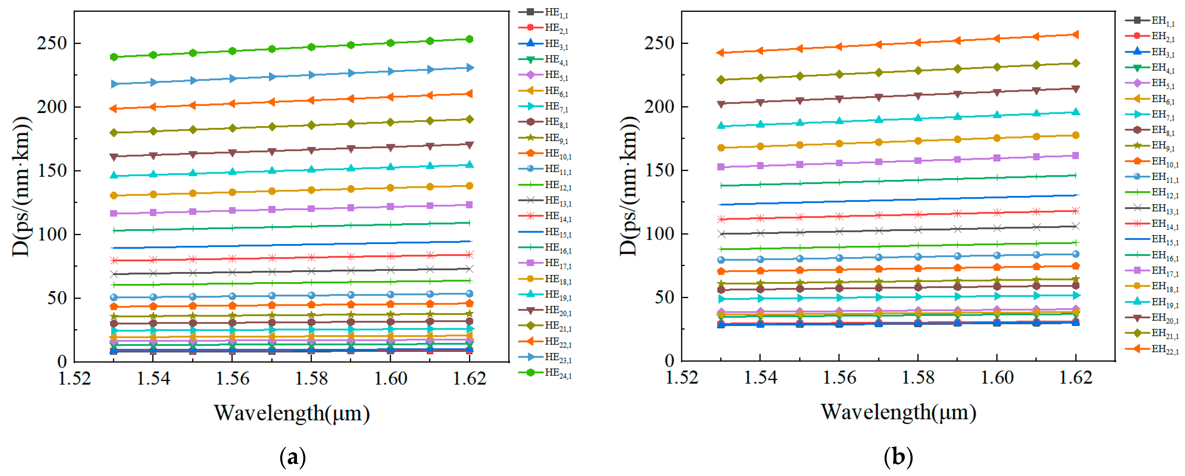
Figure 10a,b illustrate how dispersion varies with wavelength for the HE and EH modes within the 1.53–1.62 µm range. As shown, the dispersion increases with increasing wavelength, and this trend becomes more pronounced for higher-order modes. Overall, the dispersion variation for all modes exhibits a flat profile. The minimum dispersion variation occurs for the HE2,1 mode, measuring only 0.5394 ps/(nm·km). Conversely, the maximum dispersion variation is observed in the EH22,1 mode, yet remains relatively low at 14.2728 ps/(nm·km). This approximately linear dispersion trend implies that the group velocity variations for optical signals of different frequencies propagating through the fiber are relatively uniform, which helps minimize transmission time differences caused by inter-frequency dispersion, thereby suppressing signal distortion and broadening effects induced by dispersion.

3.5. Mode Quality (η)

Mode purity serves as a critical metric for characterizing the quality of OAM modes. Higher purity correlates with enhanced transmission stability and superior OAM signal quality, thereby significantly enhancing the performance of OAM multiplexing systems. Furthermore, higher mode purity reduces inter-modal crosstalk, ensuring higher transmission efficiency and capacity in optical fibers. Therefore, mode purity plays a pivotal role in characterizing the performance properties of OAM-supporting PCFs, as it directly influences mode crosstalk and transmission fidelity. To characterize mode fidelity, we use the following formula for mode purity calculation [15]:
η = I r I c = r i n g E ( x , y ) 2 d x d y c r o s s - s e c t i o n E ( x , y ) 2 d x d y
Here, the numerator Ir denotes the optical intensity within the high-index ring waveguide, while the denominator Ic represents the cross-sectional light intensity of the proposed photonic crystal fiber. The integrand E(x, y) in the double integral, like in Formula (3), also represents the transverse electric field distribution.
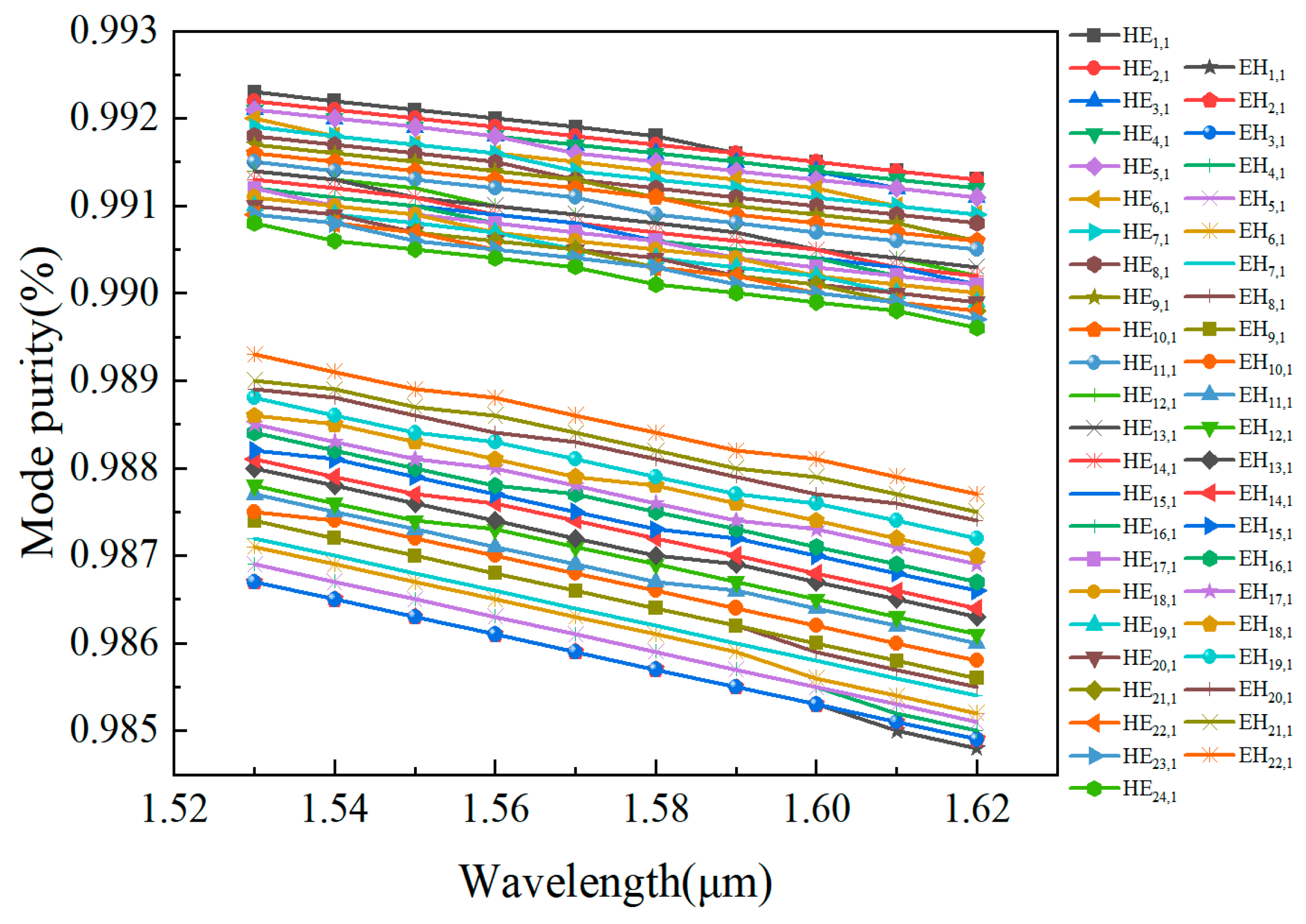
Figure 11 illustrates how mode purity varies with wavelength for all hybrid modes across the 1.53–1.62 µm band. It is evident that HE modes demonstrate greater mode purity compared to EH modes, with both types experiencing a gradual reduction in purity as wavelength increases. This trend occurs because longer wavelengths diminish the fiber’s capacity to confine light effectively, resulting in lower mode purity. Specifically, HE modes exhibit purity levels from 98.9% to 99.2%, whereas EH modes range between 98.5% and 98.9%. Notably, all modes sustain purity above 98.5%, confirming that both HE and EH eigenmodes in our designed fiber maintain exceptional purity, ensuring superior orbital angular momentum state transmission.

3.6. Numerical Aperture (NA)

Numerical aperture represents the maximum angular extent at which an optical fiber can efficiently gather and emit light. This unitless parameter serves as a key indicator of the fiber’s light-capturing and transmission capabilities, being determined by both the operating wavelength and effective mode field area. Theoretically, a larger numerical aperture is more desirable. The formula for calculating the numerical aperture is given by [14]:
NA = 1 + π A e f f λ 2 1 / 2
where λ is the wavelength and the range of λ in this article is 1530–1620 nm. Aeff, denoting the effective mode field area, is determined via Equation (3).
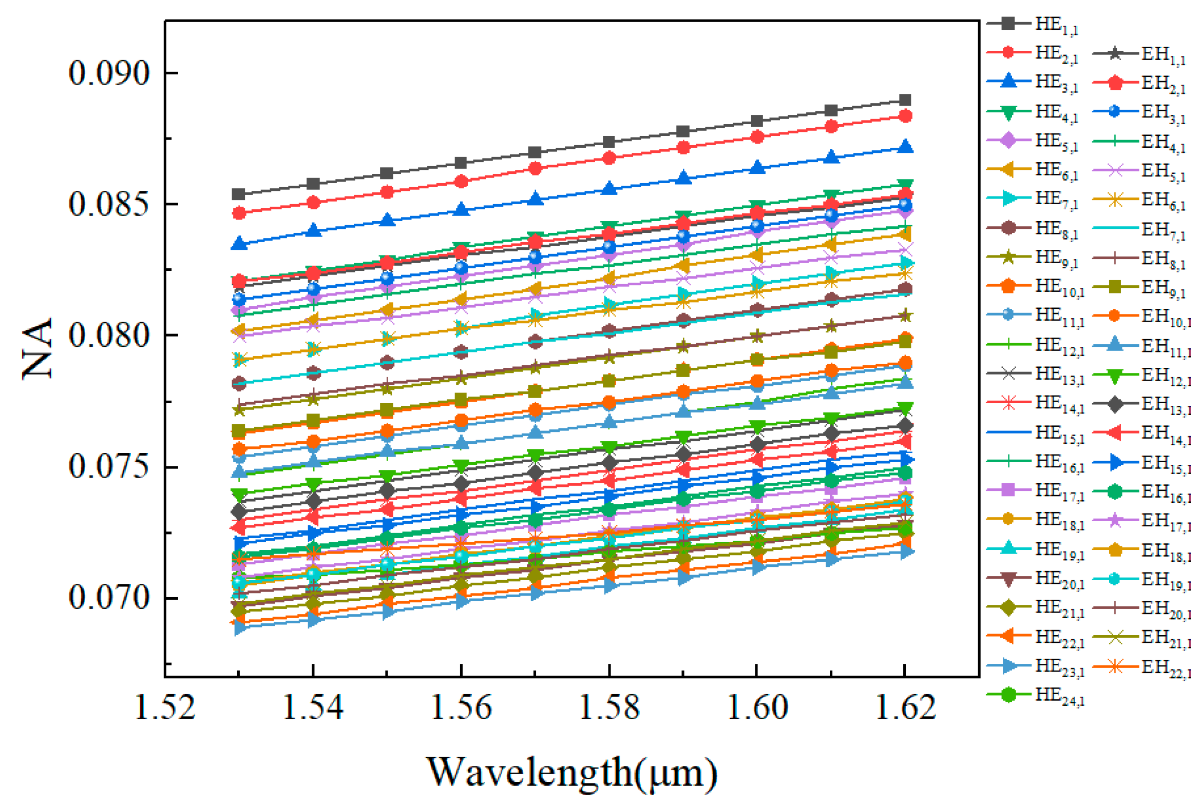
Figure 12 plots NA versus wavelength for HE modes up to the 24th order and EH modes up to the 22nd order. As observed, as the wavelength increases, the NA continuously rises, resulting in gradual enhancement of light-collecting capability. Within the wavelength band of 1.53–1.62 µm, the NA values are concentrated between 0.0689 and 0.089.

3.7. Comparison

Table 1 presents a comprehensive performance comparison between the proposed ring-core anti-resonant photonic crystal fiber and existing OAM-supporting ring-core photonic crystal fibers. Our design demonstrates a strategically balanced profile. It features an anti-resonant cladding structure, which ensures straightforward fabrication through the established two-step stack-and-draw process [23,24,25]: First, the high-refractive-index ring-core is fabricated and fixed via deposition. Then, three layers of anti-resonant capillaries are assembled by tangentially fixing the second and third layers before inserting them into the pre-aligned first capillary layer. Subsequently, the integrated cladding structure is placed into an outer jacket tube to form the PCF preform, which is finally drawn into fiber. Simultaneously, the proposed fiber can also transmit 90 high-purity OAM modes (>98.5% modal purity), enabling superior multiplexing fidelity in optical communication systems. In contrast, Ref. [12] achieves higher mode capacity (101 OAM modes) but requires complex circular–rectangular air holes that substantially increase manufacturing complexity. Ref. [15]’s dual-ring-core PCF enhances mode count through a dual-waveguide design yet demands sub-micron concentric alignment precision during fabrication. Refs. [16,18] leverage doped-ring architectures to achieve high refractive-index contrast for supporting numerous modes, but their multilayer air-structured claddings introduce significant production challenges. Critically, the proposed fiber exhibits superior performance in confinement loss, minimum dispersion variation, and nonlinear coefficient, which collectively ensure enhanced signal transmission quality when applied to optical communication systems.

4. Conclusions

In this paper, an OAM-supporting ring-core anti-resonant photonic crystal fiber is proposed. The fiber features a high-index-doped ring-core surrounded by a three-layer nested anti-resonant cladding. This design readily and efficiently creates a refractive index disparity and allows for more OAM modes propagation. The research results demonstrate that the fiber supports 1st–23rd-order OAM modes (a total of 90) across the 1530–1620 nm spectral window. Moreover, the maximum confinement loss of all supported modes lies at only 10−8 dB/m. Such low losses greatly contribute to the reliable extended-range propagation behavior of OAM modes. Additionally, the fiber has a large effective mode field area and a low nonlinear coefficient. The minimum effective mode field area is as large as 101.41 μm2, while the maximum nonlinear coefficient is only 1.05 W−1·km−1. In terms of dispersion characteristic, it exhibits very flat variation, with a minimum dispersion variation of just 0.5394 ps/(nm·km). In the end, the mode purity exceeds 98.5%, and the numerical aperture ranges from 0.0689 to 0.089. Moreover, the fiber can be fabricated through the established two-step stack-and-draw process, and the manufacturing technology is simple. Given these advantages, the proposed ring-core anti-resonant photonic crystal fiber demonstrates significant potential for high-capacity fiber-optic transmission.

Author Contributions

Conceptualization, H.S.; methodology, H.S.; software, H.S.; validation, H.S. and P.W.; formal analysis, H.S.; investigation, H.S.; resources, H.S.; data curation, H.S.; writing—original draft preparation, H.S.; writing—review and editing, L.J. and C.W.; visualization, J.W. and L.R.; supervision, P.W.; project administration, H.S.; funding acquisition, H.S. All authors have read and agreed to the published version of the manuscript.

Funding

This research was funded by Science Research Project of Hebei Education Department (Grant No. QN2024081), Doctoral Innovation Fund of Tangshan University (Grant No. BC202214), Research Projects of Talent Project Training Funds of Hebei Province (Grant No. C20221067), Talent Project of Tangshan City (Grant No. A202110009) and Science and Technology Project of Tangshan City (Grant Nos. 22130216G/23130222E/22130223G).

Data Availability Statement

The data that support the findings of this study are available from the author upon reasonable request.

Conflicts of Interest

The authors declare no conflicts of interest.

References

  1. Richardson, D.J.; Fini, J.M.; Nelson, L.M. Space-division multiplexing in optical fibres. Nat. Photonics 2013, 7, 354–362. [Google Scholar] [CrossRef]
  2. Saitoh, K.; Matsuo, S. Multicore Fiber Technology. J. Light. Technol. 2016, 34, 55–66. [Google Scholar] [CrossRef]
  3. Sillard, P.; Bigot-Astruc, M.; Molin, D. Few-Mode Fibers for Mode-Division-Multiplexed Systems. J. Light. Technol. 2014, 32, 2824–2829. [Google Scholar] [CrossRef]
  4. Brunet, C.; Vaity, P.; Messaddeq, Y.; LaRochelle, S.; Rusch, L.A. Design, fabrication and validation of an OAM fiber supporting 36 states. Opt. Express 2014, 22, 26117–26127. [Google Scholar] [CrossRef] [PubMed]
  5. Wang, J.; Yang, J.Y.; Fazal, I.M.; Ahmed, N.; Yan, Y.; Huang, H.; Ren, Y.X.; Yue, Y.; Dolinar, S.; Tur, M.; et al. Terabit free-space data transmission emploving orbital angular momentum multiplexing. Nat. Photonics 2012, 6, 488–496. [Google Scholar] [CrossRef]
  6. Li, S.; Wang, J. Multi-Orbital-Angular-Momentum Multi-Ring Fiber for High-Density Space-Division Multiplexing. IEEE Photonics J. 2013, 5, 7101007. [Google Scholar]
  7. Gregg, P.; Kristensen, P.; Ramachandran, S. Conservation of orbital angular momentum in air-core optical fibers. Optica 2015, 2, 267–270. [Google Scholar] [CrossRef]
  8. Brunet, C.; Rusch, L.A. Optical fibers for the transmission of orbital angular momentum modes. Opt. Fiber Technol. 2017, 35, 2–7. [Google Scholar] [CrossRef]
  9. Yue, Y.; Zhang, L.; Yan, Y.; Ahmed, N.; Yang, J.Y.; Huang, H.; Ren, Y.X.; Dolinar, S.; Tur, M.; Willner, A.E. Octave-spanning supercontinuum generation of vortices in an As2S3 ring photonic crystal fiber. Opt. Lett. 2012, 37, 1889–1891. [Google Scholar] [CrossRef]
  10. Tian, W.; Zhang, H.; Zhang, X.G.; Xi, L.X.; Zhang, W.B.; Tang, X.F. A circular photonic crystal fiber supporting 26 OAM modes. Opt. Fiber Technol. 2016, 30, 184–189. [Google Scholar] [CrossRef]
  11. Bai, X.L.; Chen, H.M.; Yang, H.H. Design of a circular photonic crystal fiber with square air-holes for orbital angular momentum modes transmission. Optik 2018, 158, 1266–1274. [Google Scholar] [CrossRef]
  12. Hong, S.; Lee, Y.S.; Choi, H.; Quan, C.; Li, Y.; Kim, S.; Oh, K. Hollow Silica Photonic Crystal Fiber Guiding 101 Orbital Angular Momentum Modes Without Phase Distortion in C plus L Band. J. Light. Technol. 2019, 38, 1010–1018. [Google Scholar] [CrossRef]
  13. Wang, W.C.; Sun, C.Y.; Wang, N.; Jia, H.Z. A design of nested photonic crystal fiber with low nonlinear and flat dispersion supporting 30+ 50 OAM modes. Opt. Commun. 2020, 471, 125823. [Google Scholar] [CrossRef]
  14. Zhao, L.J.; Zhao, H.Y.; Xu, Z.N.; Liang, R.Y. A design of novel photonic crystal fiber with low and flattened dispersion for supporting 84 orbital angular momentum modes. Commun. Theor. Phys. 2021, 73, 085501. [Google Scholar] [CrossRef]
  15. Yang, M.X.; Liu, W.C.; Song, Y.K.; Wang, J.N.; Wei, Z.C.; Meng, H.Y.; Liu, H.Z.; Huang, Z.M.; Xiang, L.J.; Li, H.X.; et al. A design of dual guided modes ring-based photonic crystal fiber supporting 170+62 OAM modes with large effective mode field area. Appl. Phys. B-Lasers Opt. 2022, 128, 38. [Google Scholar] [CrossRef]
  16. Zhang, L.; Zhang, K.; Peng, J.; Deng, J.; Yang, Y.; Ma, J. Circular photonic crystal fiber supporting 110 OAM modes. Opt. Commun. 2018, 429, 189–193. [Google Scholar] [CrossRef]
  17. Israk, M.F.; Razzak, M.A.; Ahmed, K.; Hassan, M.M.; Kabir, M.A.; Hossain, M.N.; Paul, B.K.; Dhasarathan, V. Ring-based coil structure photonic crystal fiber for transmission of orbital angular momentum with large bandwidth: Outline, investigation and analysis. Opt. Commun. 2020, 473, 126003. [Google Scholar] [CrossRef]
  18. Wang, X.H.; Deng, D.D.; Xu, L.; Ji, X.C.; Zhang, H.; Rui, J.W.; Mao, S.; Wang, Y.; Gao, Z.; Jiang, C.L.; et al. Propagating OAM modes through a regular octagonal photonic crystal fiber with a flat dispersion. Phys. Scr. 2025, 100, 035117. [Google Scholar] [CrossRef]
  19. Belardi, W.; Knight, J.C. Hollow antiresonant fibers with reduced attenuation. Opt. Lett. 2014, 39, 1853–1856. [Google Scholar] [CrossRef] [PubMed]
  20. Gao, S.F.; Wang, Y.Y.; Ding, W.; Jiang, D.L.; Gu, S.; Zhang, X.; Wang, P. Hollow-core conjoined-tube negative-curvature fibre with ultralow loss. Nat. Commun. 2018, 9, 2828. [Google Scholar] [CrossRef] [PubMed]
  21. Jin, Y.L.; Zhang, X.; Yao, J.Y.; Gu, S.; Wang, P. Low-loss mid-infrared composite hollow core anti-resonant fiber. Infrared Laser Eng. 2025, 54, 20240468. [Google Scholar]
  22. Hassan, M.M.; Abdulrazak, L.F.; Alharbi, A.G.; Ahmed, K.; Bui, F.M.; Al-Zahrani, F.A.; Uddin, M.S. Novel approach of anti-resonant fiber with supporting 64 orbital angular momentum modes for optical communication. Alex. Eng. J. 2022, 61, 9891–9900. [Google Scholar] [CrossRef]
  23. Gao, S.F.; Chen, H.; Sun, Y.Z.; Xiong, Y.F.; Yang, Z.J.; Zhao, R.; Ding, W.; Wang, Y.Y. Fourfold truncated double-nested antiresonant hollow-core fiber with ultralow loss and ultrahigh mode purity. Optica 2025, 12, 56–61. [Google Scholar] [CrossRef]
  24. Kosolapov, A.F.; Alagashev, G.K.; Kolyadin, A.N.; Pryamikov, A.D.; Biryukov, A.S.; Bufetov, I.A.; Dianov, E.M. Hollow-core revolver fibre with a double-capillary reflective cladding. Quantum Electron. 2016, 46, 267–270. [Google Scholar] [CrossRef]
  25. Chen, B.; Kühlthau, T.; Kleem, G.; Graf, T.; Abdou Ahmed, M. Design, fabrication, and characterization of dual-wavelength inhibited-coupling guiding hollow-core fibers. Appl. Phys. B 2025, 131, 58. [Google Scholar] [CrossRef]
Figure 1. Cross-sectional schematic of the proposed ring-core anti-resonant fiber.
Photonics 12 00906 g001
Figure 2. (a) neff versus wavelength for 1st–24th-order HE modes; (b) neff versus wavelength for 1st–22nd-order EH modes.
Photonics 12 00906 g002
Figure 3. Δneff versus wavelength for 1st–23rd-order OAM.
Photonics 12 00906 g003
Figure 4. (ad) Electric fields along the z-direction of even-modes for HE3,1, HE9,1, HE15,1 and HE21,1; (eh) Electric fields along the z-direction of even-modes for EH1,1, EH7,1, EH13,1 and EH19,1; (il) Normalized electric fields for l = ±2/±8/±14/±20.
Photonics 12 00906 g004
Figure 5. (ad) Right-rotation phase distributions for l = −2/−8/−14/−20; (eh) Left-rotation phase distributions for l = +2/+8/+14/+20.
Photonics 12 00906 g005aPhotonics 12 00906 g005b
Figure 6. (a) CL versus wavelength for 1st–24th-order HE modes; (b) CL versus wavelength for 1st–22nd-order EH modes.
Photonics 12 00906 g006
Figure 7. Bending losses of partial hybrid modes versus bending radius.
Photonics 12 00906 g007
Figure 8. (a) Aeff versus wavelength for 1st–24th-order HE modes; (b) Aeff versus wavelength for 1st–22nd-order EH modes.
Photonics 12 00906 g008
Figure 9. (a) γ versus wavelength for 1st–24th-order HE modes; (b) γ versus wavelength for 1st–22nd-order EH modes.
Photonics 12 00906 g009
Figure 10. (a) Dispersion versus wavelength for 1st–24th-order HE modes; (b) Dispersion versus wavelength for 1st–22nd-order EH modes.
Photonics 12 00906 g010
Figure 11. Mode purity versus wavelength for all hybrid eigenmodes.
Photonics 12 00906 g011
Figure 12. Numerical aperture versus wavelength for all hybrid eigenmodes.
Photonics 12 00906 g012
Table 1. Comparison of key characteristics between the proposed PCF and previously reported PCF.
ReferencesStructure TypeMode NumberΔneffCLmin
dB/m
γmax
W−1·km−1
ΔDmin
ps/(nm·km)
Mode Purity
[10]Circular-hole-cladding PCF260.0095 × 10−102.0839.84-
[11]Rectangular-hole-cladding PCF460.0081 × 10−102.580.21-
[12]Hybrid-hole-cladding PCF101>1 × 10−41 × 10−8--78.7–90%
[13]Dual-ring-core PCF30 + 500.0031 × 10−82.652.7-
[14]Dual-ring-core PCF62 + 220.00455 × 10−134.90.791.7–97%
[15]Dual-ring-core PCF170 + 620.00351.56 × 10−121.55.992.5–96.5%
[16]Doped-ring-core PCF1100.0011 × 10−72.832-
[17]Doped-ring-core PCF560.041.74 × 10−11436.90789–93.7%
[18]Doped-ring-core PCF1140.00151 × 10−140.6-95–97.6%
[21]Anti-resonant PCF640.072.7 × 10−6-8.83897–99%
ProposedDoped-ring-core anti-resonant PCF900.00415.16 × 10−121.050.539498.5–99.2%
Disclaimer/Publisher’s Note: The statements, opinions and data contained in all publications are solely those of the individual author(s) and contributor(s) and not of MDPI and/or the editor(s). MDPI and/or the editor(s) disclaim responsibility for any injury to people or property resulting from any ideas, methods, instructions or products referred to in the content.